Clock Synchronization for Many-core
Processors
Filipe Miguel Teixeira Monteiro
Mestrado Integrado em Engenharia Eletrotécnica e de Computadores Supervisor: Pedro Alexandre Guimarães Lobo Ferreira do Souto
Multiprocessor systems such as multi-core processors have a very relevant presence in modern lives, from computing systems such as smartphones to desktop computers.
In contrast, their adoption in real-time systems was slower but has been steadily increasing. In recent years a new architecture for parallel processors is starting to be introduced in this strict application domain. These processors are usually called many-core processors.
Clock synchrony can be a critical feature of this type of system. Therefore, this dissertation focuses on clock synchronization for this new multiprocessor architecture, and it has the objective of implementing and evaluating a software based clock synchronization algorithm on Kalray’s MPPA R - 256 MANYCORE architecture.
To determine the best approach for our problems, we provide a careful characterization of the target platform based on an experimental timing analysis of the clock source and the communica-tion methods available on the MPPA platform.
The proposed synchronization is divided in two hierarchical levels, to accommodate for the hardware’s heterogeneity. Both synchronization algorithms are adapted from the Precision Tim-ing Protocol (IEEE 1588) used in distributed systems, but were implemented usTim-ing two different programming paradigms, shared memory and message passing.
In addition to the main body of the algorithm, a delay asymmetry correction was implemented in each of the synchronization’s levels in order to increase their accuracy and stability.
Furthermore, a set of experiments was done with the purpose of evaluating the quality of the implemented synchronization, and it was verified that our approach achieves good results (maxi-mum offsets up to 5 ns inside clusters and up to 250 ns between clusters), even if it sacrifices the higher precision of hardware clock synchronization methods for the higher scalability a software implementation.
Sistemas de multiprocessadores como os processadores multi-core têm uma presença muito rel-evante na vida moderna, em sistemas computacionais como smartphones ou computadores pes-soais.
Em contraste, a sua adoção em sistemas de tempo-real foi mais lenta mas tem vindo a aumentar todos os anos.
Recentemente surgiu uma nova arquitetura de processadores paralelos, normalmente chama-dos como processadores many-core, que está a começar a ser introduzida neste tipo de aplicação. Sincronismo de relógio pode ser uma característica crítica deste tipo de sistema. Assim, esta dissertação foca-se em sincronização de relógio para esta nova arquitetura de multiprocessadores, e tem como objectivo a implementação e avaliação de um algoritmo de sincronização de relógio na arquitetura MPPA R - 256 MANYCORE da Kalray.
Para determinar a melhor abordagem para os nossos problema apresentamos uma caracteriza-ção temporal da plataforma utilizada, baseada numa análise experimental aos parâmetros tempo-rais do relógio e dos métodos de comunicação disponíveis.
A sincronização proposta está dividida em dois níveis hierárquicos, para acomodar a hetero-geneidade do hardware utilizado. Ambos os algoritmos de sincronização foram adaptados do al-goritmo PTP (IEEE - 1588) utilizado em sistemas distribuídos mas foram implementados usando dois paradigmas diferentes, memoria partilhada e a troca de mensagens.
Para além do corpo principal do algoritmo, foi também implementado um método de correção das assimetrias dos atrasos de comunicação em ambos níveis da sincronização para aumentar a sua precisão e estabilidade.
Adicionalmente, um conjunto de experiências foi realizado com o objectivo de avaliar a qual-idade da sincronização. Foi verificado que a nossa abordagem obteve resultados positivos (offset máximo até 5 ns dentro dos clusters e até 250 ns entre clusters), mesmo sacrificando a maior pre-cisão de um sincronização através de hardware dedicado em troca de uma maior escalabilidade de uma implementação em software.
Quero agradecer ao meu orientador, Pedro Souto pela motivação e ajuda que me deu ao longo de todo o desenvolvimento desta dissertação.
À equipa do CISTER por disponibilizar as suas instalações e por me permitir acesso á plataforma em que esta dissertação foi implementada. A special thanks to Borislav Nikoli´c for helping me "get to know" the platform in the earlier stages of this dissertation.
A todos os meus colegas e amigos dos últimos 5 anos, com o qual tive o prazer de partilhar esta caminhada.
A toda a minha família, em especial á minha Mãe, Avó e Tios, por tudo o que fizeram por mim. Sem vocês não estava onde estou nem era quem sou.
Por fim, um agradecimento muito especial para a minha melhor amiga e companheira de todas as horas, Lúcia Vaz, obrigada por toda a motivação que me deste durante todo este período de dissertação e por tudo o que me dás todos os dias. Adoro-te, 16.
Filipe Monteiro
Ray Cummings, The Girl in the Golden Atom
1 Introduction 1
1.1 Context and motivation . . . 1
1.2 Objectives . . . 3
1.3 Document Structure . . . 3
2 State of the art 5 2.1 Many-core processor architectures . . . 5
2.1.1 Interconnect networks . . . 6
2.1.2 Memory system . . . 9
2.1.3 Examples of Many-Core Processor Architectures . . . 13
2.2 Clock Synchronization Algorithms . . . 21
2.2.1 Probabilistic Clock Synchronization . . . 22
2.2.2 Network Time Protocol . . . 22
2.2.3 Precision Time Protocol . . . 23
2.2.4 Distributed fault tolerant algorithms . . . 25
2.2.5 Gradient clock synchronization . . . 28
2.2.6 Converge-to-Max Algorithm . . . 29
2.2.7 Reachback Firefly Algorithm . . . 30
2.3 Clock Synchronization for Multi-Core Processors . . . 32
3 Per-Core Clock Implementation 35 3.1 Clock Definition . . . 35
3.2 Hardware Clock Source . . . 35
3.2.1 Time Stamp Counter . . . 35
3.2.2 Characterization of the Clock Source . . . 36
4 Clock Synchronization 41 4.1 Intra-Cluster Synchronization . . . 41
4.1.1 The Communication Methods . . . 41
4.1.2 The Synchronization Algorithm . . . 44
4.1.3 Delay Asymmetry Correction . . . 46
4.2 Inter-Cluster Synchronization . . . 47
4.2.1 The Communication Method . . . 47
4.2.2 The Synchronization Algorithm . . . 49
4.2.3 Delay Asymmetry Correction . . . 50
4.3 Code Structure . . . 52
5 Evaluation of the Synchronization 53
5.1 Intra-Cluster Synchronization . . . 53
5.1.1 Data export method . . . 53
5.1.2 Results . . . 53
5.2 Inter-Cluster Synchronization . . . 56
5.2.1 Data export method . . . 56
5.2.2 Results . . . 57
6 Conclusions and Future Work 61 6.1 Future Work . . . 62
A Multiprocessor Operating Systems 63 A.1 SMP Linux . . . 63
A.2 PikeOS . . . 64
A.3 eMCOS . . . 65
B Source Code 67 B.1 Common routines and variables . . . 67
B.1.1 common.h . . . 67 B.1.2 common.c . . . 69 B.2 Intra-Cluster Synchronization . . . 71 B.2.1 internal_sync.h . . . 71 B.2.2 internal_sync.c . . . 74 B.3 Inter-Cluster Synchronization . . . 80 B.3.1 external_sync.h . . . 80 B.3.2 external_sync.c . . . 83 References 91
2.1 Bus connected multiprocessor [1] . . . 6
2.2 Examples of different NoC topologies[2] . . . 7
2.3 The X-Y routing algorithm; (a) The allowed turns by the X-Y routing algorithm; (b) Examples of possible packet routes [2] . . . 8
2.4 NoC switching techniques. (a) Store-and-forward switching. (b) Whormhole switching [2] . . . 8
2.5 (a) The UMA multiprocessor configuration. (b) The NUMA multiprocessor con-figuration . . . 9
2.6 The Distributed Memory multiprocessor configuration . . . 10
2.7 Common multiprocessor node structures. (a) UMA configuration. (b) NUMA configuration. (c) Distributed memory configuration . . . 11
2.8 Block diagram of the TeraFLOPS processor architecture [3] . . . 13
2.9 Block diagram of the Single-Chip Cloud Computer processor architecture [4] . . 14
2.10 (a) Block diagram of the TILE64 processor. (b) Array of tiles connected by the five NoCs [5]. . . 15
2.11 Block diagram of the MPPA-256 processor [6] . . . 17
2.12 Block diagram of a MPPA cluster [6] . . . 18
2.13 Graphical representation of clocks with diferent tick rates [7] . . . 21
2.14 The NTP algorithm message exchange between a client and a time server . . . . 23
2.15 PTP message sequence chart . . . 24
2.16 Example of a two faced clock at node A [8] . . . 25
2.17 Authenticated clock synchronization algorithm . . . 27
2.18 Broadcast primitive for the non-authenticated algorithm . . . 27
2.19 Non-Authenticated clock synchronization algorithm . . . 27
2.20 Broadcast primitive for the non-authenticated algorithm with crash/omission fault models . . . 28
2.21 Simplistic gradient clock synchronization protocol [9] . . . 29
2.22 Converge-to-max algorithm . . . 29
2.23 Synchronization algorithm acording with the original model [10] . . . 30
2.24 Effects of the Reachback firefly algorithm [10] . . . 31
2.25 Synchronization Algorithm with IPI communication [11] . . . 33
2.26 Synchronization Algorithm with Cache Coherence communication [11] . . . 33
3.1 Code to directly read the TSC trough the assembly instruction . . . 36
3.2 Master-slave barrier operation to periodicly sample of the TSC . . . 39
4.1 Pseudocode of the protected access to shared data . . . 42
4.2 Average Delay communication inside the compute clusters . . . 44
4.3 Message sequence chart of the intra-cluster Synchronization . . . 45
4.4 Flowchart of the adapted DAC model for the intra-cluster synchronization . . . . 47
4.5 Example of the large systematic delay assymetry . . . 49
4.6 Offset estimation with the constant delay compensation . . . 50
4.7 Flowchart of the adapted DAC model for the inter-cluster synchronization . . . . 51
5.1 First 100 Rounds of the intra-cluster synchronization results. (a) Experiment 1, T = 1s. (b) Experiment 2, T = 100ms. (c) Experiment 3, T = 10ms. . . 54
5.2 Intra-cluster synchronization results. (a) Experiment 1, T = 1s. (b) Experiment 2, T = 100ms. (c) Experiment 3, T = 10ms. . . 55
5.3 Offset calculation for the evaluation of the inter-cluster synchronization . . . 56
5.4 Experiment 1. Master: Cluster 6 (a) Offsets between each slave and the master cluster. (b) Absolute maximum and minimum offsets during the experiment . . . 57
5.5 Experiment 2. Master: Cluster 14 (a) Offsets between each slave and the master cluster. (b) Absolute maximum and minimum offsets during the experiment . . . 58
5.6 Experiment 3. Master: Cluster 5 (a) Offsets between each slave and the master cluster. (b) Absolute maximum and minimum offsets during the experiment . . . 58
5.7 Experiments without the constant delay compensation (a) Master: Cluster 5. (b) Master: Cluster 6. . . 59
2.1 Performance propieties of the various UDN communication methods . . . 16
2.2 MPPAs IPC software connectors . . . 19
2.3 MPPAs PCIe software connectors . . . 20
3.1 Results obtained by concurrently calling the __k1_read_dsu_timestamp() function in every core of a cluster . . . 37
3.2 Results obtained by concurrently calling the assembly instruction in each core of a cluster . . . 38
4.1 POSIX signals latency experiment results . . . 43
4.2 NodeOS events latency experiment results . . . 44
4.3 Results of the latency experiment with a portal connector . . . 48
AIO Asynchronous Input/Output AMP Asymmetric Multiprocessor API Application Protocol Interface ARINC Aeronautical Radio Incorporated
CMOS Complementary Metal Oxide Semiconductor CPU Central Processing Unit
DAC Delay Asymmetry Correction DSU Debug and System Unit
eMCOS embedded Many-Core Operating System FIFO First In First Out
FLIT FLow control unIT
FLOPS Floating Point Operations Per-Second FTA Fault Tolerant Average
GALS Globally Asynchronous Locally Synchronous
GDB GNU Debugger
GDDR Graphics Double Data rate
GNU GNU is Not Unix
GPU Graphics Processing Unit HTML HyperText Markup Language
I/O Input/Output
IA Intel Architecture
IEEE Institute of Electrical and Electronics Engineers IPC Inter-Process Communication
IPN Inter-Processor Network ISA Instruction Set Architecture KILL Kill If Less than Linear MIC Many Integrated Cores
MOSFET Metal Oxide Semiconductor Field Effect Transistor MPI Message Passing Interface
MPPA Multi-Purpose Processing Array NTP Network Time Protocol
NUMA Non-Uniform Memory Access NUMA Non-Uniform Memory Access
NoC Network on Chip
ODC2 On-Demand Cache Coherence
OS Operating System
OpenMP Open Multi-processing
PCIe Peripheral Component Interconnect Express xv
PE Processing Element
POSIX Portable Operating System Interface PTP Precision Time Protocol
RFA Reachback Firefly Algorithm RISC Reduced Instruction Set Computer
RM Resource Manager
RMA Remote Memory Access RTD Round Trip Delay
RTEMS Real Time Executive for Multiprocessor Systems RTOS Real Time Operating System
Rx Receive
SCC Single-Chip Cloud Computer SCI Scalable Coherent Interface SDK Software Development Kit SMP Symmetric Multiprocessor SMP Symmetric Multiprocessor TDMA Time Division Multiple Access TSC Time Stamp Counter
Tx Transmit
UMA Uniform Memory Access VLIW Very Long Instruction Word VM Virtual Machine
Introduction
1.1
Context and motivation
This dissertation focuses on clock synchronization in real-time systems for many-core platforms. The operation of most common systems is considered correct if the produced output values are consistent with its functional specification. This is not true for real-time systems. These systems are required not only to produce the correct results but also to do it in a timely fashion. This means that real-time systems are subject to a set of timing constraints, therefore they need to produce the expected correct results within a specified time window. Not satisfying these constraints can have consequences that range from quality losses in a non-critical service, to the complete failure of the system.
The evolution of modern technology requires even better and faster computational devices. Understandable, this extended to real-time systems.
For most common applications this need has been answered by a new type of processor archi-tecture that we call multi-core processors. This type of processor features multiple independent processing units that can communicate with each other via a multitude of possible different mech-anisms, share the same memory space, and have the objective of exploiting application parallelism to reach the desired performance increase. These processors are now the most common computer architecture. However, the adoption of multiprocessors in the real-time systems domain has been considerably slower, especially in safety-critical systems, which are subject to strict characteriza-tion processes.
These types of architectures are the next logical step for real-time systems, but there are still concerns regarding their deployment in these applications because of the unpredictability that can arise from the sharing of resources among cores.
The availability of clock synchrony among the different cores may help in increasing this pre-dictability. Furthermore, the precision of the processor clocks can greatly impact the performance of these platforms in real-time applications
We can see the benefits of synchronized clocks in these architectures by analyzing a class of multiprocessor real-time algorithms known as semi-partitioned scheduling.
These algorithms use the concept of workload migration to optimize core utilization. In this approach, the execution pattern of a migrative task is defined at design time. This means that the execution of a task (job) can be divided in smaller pieces (sub-jobs) to be performed in multiple cores. In some algorithms, tasks will always spend the same amount of time in a given core before migrating. Thus it is important to guarantee the order of each sub-job of a task instance.
A straightforward way to enforce this order constraint is to take advantage of the available inter-process communication (IPC) mechanism. With this solution after the end of a sub-job, the scheduler in that core will send a message to the core that will execute the next piece of this instance. This sub-job will only be queued for scheduling when the message is received and processed, which means that the response time of each sub-job is heavily influenced by communi-cation delays. In certain platforms, message contention can be rather frequent and it will result in substantial delays. It is understandable that this migration scheme can lead to a very pessimistic worst-case response time and therefore can cause low core utilization.
A better approach reduces IPC to a single message. Upon the scheduling of a migrating job, the respective scheduler can send a message to all cores that will execute the various sub-jobs. With resource to a high-precision timer and estimating the network delay of the original message, each core can appropriately schedule their respective sub-jobs. Although, the effect of communication uncertainties is reduced to the only exchanged message, the delay estimation can still lead to a substantial amount of pessimism.
A way to reduce this pessimism is to use per-core synchronized clocks. The scheduler that launches the migrative task will also send a message to all cores that will execute the respective sub-jobs, but in this scheme the message will contain a time stamp of the moment it was sent. Since every core shares the same "view" of time, the IPC delay can be measured rather then estimated. This will substantially reduce the pessimism of the scheduling and therefore improve core utilization.
Another relevant application of synchronized clocks in multiprocessor architectures is in re-source management algorithms. A concrete example, PikeOS [13], a known multiprocessor real-time operating system (RTOS), implements atomic access to shared recourses trough real-time multi-plexing. In simpler terms, each process can access a resource only at a specific predetermined time slice. To guarantee that two different processes do not access the same resource simultaneously, they need to share the same time base.
In order to address this problem, of synchronization among multiple cores of multiproces-sors, a dissertation was developed last year that focused on common off-the-shelf Intel multi-core architectures[11]. We will go more in depth about this work on Section2.3.
In recent years a new type of multiprocessor has been the target of significant research and development, the industry calls it a many-core processor, which received its name because it takes the focus on parallelism to the extreme by possibly harboring hundreds of processing cores, unlike their multi-core counterparts that rarely have more than a single digit number of cores. This dif-ference brings along some key architectural changes that allow them to have such a large number of processing cores.
This dissertation will focus on software based clock synchronization for this new type of pro-cessors and it will try to make them more suitable for real-time systems.
This work was developed on Kalray’s MPPA-256 many-core processor (Section2.1.3.4), since it has some key futures that facilitate the evaluation of the proposed synchronization.
1.2
Objectives
In digital synchronous circuits, clock synchrony is usually enforced by a multitude of hardware design methodologies.
In this dissertation we take a different approach and propose to develop, implement, and ex-perimentally evaluate a software based clock synchronization algorithm for a many-core processor architecture. The latter is crucial to assess applicability of the proposed algorithm to a given ap-plication.
Summarizing, this dissertation aims to create a way to reduce the effects of clock skew in many-core architectures, so that in the future we can take full advantage of this new hardware architecture and achieve improved performance in real-time applications.
1.3
Document Structure
The remaining of this document is comprised of five more chapters. In Chapter2we review some relevant state of the art concepts that constitute the theoretical and technological background of this dissertation. Chapter3features our definition of the clocks that are going to be synchronized and an analysis of the chosen hardware clock source. In Chapter4we describe the algorithms and communication mechanisms we used to synchronize these clocks. In Chapter5we evaluate the quality of the implemented synchronization algorithms and describe the methods that were used to extract the relevant data for their analysis. Finally, Chapter6presents the conclusions that can be derived from this dissertation and some future work that could be done to improve or extend the approach proposed in this dissertation.
State of the art
In this chapter we present some of the relevant information about the main topics that are the focus of this dissertation.
We’ll start by describing some architectural principles for multiprocessor design focusing on the most common interconnect methods and memory systems used in multiprocessor chips, we also give some examples of existing many-core processors.
The chapter is finished by a survey of some clock synchronization algorithms used in dis-tributed systems.
A review of some multiprocessor operating systems can be found in annexA. This was done in the earlier stages of this dissertation but proved not very relevant to our work.
2.1
Many-core processor architectures
Over the years, the need for more functionalities and better performance from our computational systems was answered simply by increasing the number of transistors and clock frequency of the processors. This trend ended with the breakdown of what is referred as Dennard’s MOSFET scal-ing law, that failed to acknowledge the effect of power leakage while in sub-threshold switchscal-ing that is needed to do the necessary voltage scaling [14]. This means that unlike what Dennard and his team predicted in [15], power density is not constant and instead it increases with the miniaturization of transistors.
This problem, combined with the inability to efficiently dissipate the extra heat, led to a shift of the design approach to focus on parallelism. This change gave origin to the modern multi-core processors, where multiple independent processing cores are integrated into a single chip.
Initially these chips would only harbor a small number of cores, but over the years this number has increased to a point that some chips can have hundreds of cores. These highly parallel systems are called many-core processors. The differences between multi-core and many-core processors go beyond the number of cores. We can find very significant differences in, for example, the network used to interconnect the different cores or in the memory systems [16].
In this section will focus on some general design features used by many-core processors and give some examples of existing processors.
2.1.1 Interconnect networks 2.1.1.1 Bus Interconnection
One of the main architectural differences between multi and many-core processors lies on the way that multiple cores are connected between themselves. Historically, multi-cores communicate via a common shared bus.
Multi-cores that use this type of interconnection usually have a local memory and cache. This reduces the use of the shared bus, improving bandwidth and quality of service by reducing the amount of interference between the various cores. The bus topology presents several advantages in chips with a small number of processors because it simplifies the hardware design and helps in the implementation of synchronization features such as cache coherency protocols because of its inherent broadcast nature [1].
Processor 1
Processor 2
Processor N
Cache Local Memory I/O Cache Local Memory I/O Cache Local Memory I/OGlobal
Memory
Figure 2.1: Bus connected multiprocessor [1]
2.1.1.2 Network-on-Chip
With the number of integrated cores in a single chip rising, the need for a scalable interconnect topology became a very important issue. It is clear that the bus topology was not appropriate for a large number of processors, because bus contention would lead to a significant performance degradation.
To solve this problem, the concept of Network-on-chip (NoC) was born. With this type of interconnection, communication tasks are done by specific NoC elements called routers [2]. These
routers can be shared by a group of multiple cores [6] or they can be a unique per-core element [5].
There several different types of NoC topologies (Figure 2.2) and the choice of one of them will greatly influence the chip’s performance and scalability.
Figure 2.2: Examples of different NoC topologies[2]
Despite the large variety of different NoC topologies, the 2D-Mesh is clearly the most popular choice many-core platforms. The reason for this choice comes from the higher degree of scala-bility provided by this topology, since it reaches a good compromise between the total number of network links and the area used for the interconnect medium.
Therefore, let’s look closer at the 2D-mesh topology. It is easy to understand that it is not possible to establish a direct connection between any two nodes, this means that there will be times that a message will need to cross multiple intermediate routers to reach its destination. This process of making a packet reach its desired destination is called routing.
Many-core development has been favoring the implementation of deterministic routing proto-cols. A common algorithm used in 2D-mesh NoC is the X-Y routing. This routing technique is deadlock and livelock free in two-dimensional meshes and it achieves this by limiting what kind of turns a packet can do in order to reach his destination (see Figure2.3) [17]. The name of this routing algorithm comes from the fact that packets are first routed on the horizontal axis, the X axis, until it reaches the horizontal coordinate of its destination and only after this it will be routed along the vertical axis, the Y axis, until it reaches the final destination.
In the presence of traffic in specific network link a router might need to stall a packet and only send it when the necessary network link is free, this means routers will need to have some way
Figure 2.3: The X-Y routing algorithm; (a) The allowed turns by the X-Y routing algorithm; (b) Examples of possible packet routes [2]
to store data so no information is lost during the switching process, the process of choosing the network link where a message should sent to in order to reach its destination.
First router designs used the common store-and-forward switching method (Figure2.4 (a)), in this approach the router ports will need to have the necessary capacity to store an entire data packet. With the increasing size of packet sizes, this data buffering became a serious challenge in router design, up to a point when became cost prohibitive in respect to the extra area needed.
In order to solve this problem different switching methods were developed, most notably what’s now called as wormhole switching. In this technique a packet is divided into multiple FLow control unITs(FLITs) before sending, which are sent into the network in their logical order. The various FLITs then go trough the several network nodes as if they were the various stages of a synchronous pipeline (Figure 2.4 (b)). This type of switching significantly increases network throughput by increasing parallelism and can reduce the router’s storage needs to the size of a single FLIT [2].
(a) (b)
Figure 2.4: NoC switching techniques. (a) Store-and-forward switching. (b) Whormhole switch-ing [2]
2.1.2 Memory system
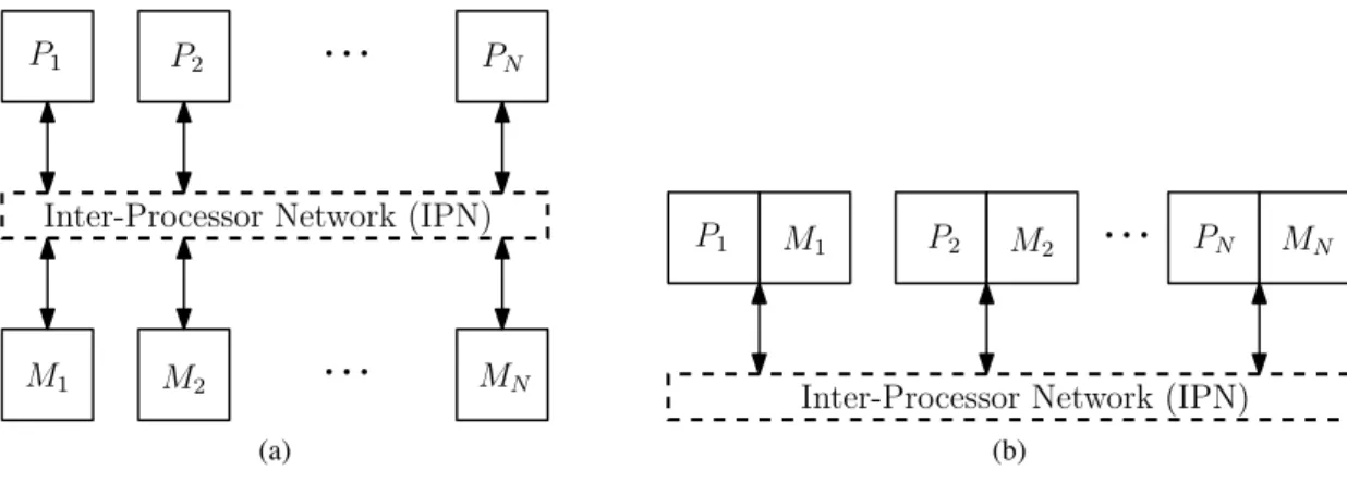
Memory systems in multi-core architectures are usually implemented in one of three configura-tions. The most common scheme is called Uniform Memory Access (UMA), in this configuration any core can access any of the connected memories by using the available interconnect medium (Figure 2.5 (a)). This scheme is not common in many-core systems for not being a very scal-able configuration since it creates large amounts of traffic in the Inter-Processor Network (IPN), which increases contention and consequently decreasing performance by increasing memory ac-cess times [18].
Another type of configuration tries to solve this scalability problem by attaching the memories directly to the processing cores, this is called Non-Uniform Memory Access (NUMA). In this architecture processors have direct access to their local memory bank but if they want to access any of the other memories they will have to use the IPN as it was used in the UMA configuration (Figure2.5(b)). It is obvious that any access to a remote memory will take considerably longer then to the local memory.
Inter-Processor Network (IPN)
...
...
M1 M2 P1 P2 MN PN (a)Inter-Processor Network (IPN)
...
M1 M2
P1 P2 PN MN
(b)
Figure 2.5: (a) The UMA multiprocessor configuration. (b) The NUMA multiprocessor configu-ration
While different, these two schemes share an important characteristic because they provide a global memory space where any of the processing cores can access any memory without needing the intervention of another core.
A different memory system configuration exists where this does not happen, where each pro-cessing core has exclusive access to its own private memory bank. This type of scheme is usually called a distributed memory system (Figure2.6). In this configuration, remote memory access re-quires the cooperation of the processor that is directly connected to the memory in question. This cooperation is achieved by some sort of message passing protocol that uses the processor’s IPN as the communication medium.
Many-core systems tend to favor either the NUMA or distributed configurations, or a variant of them, because of their higher scalability.
Inter-Processor Network (IPN)
...
...
M2 P2 MN PN P1 M1Figure 2.6: The Distributed Memory multiprocessor configuration
2.1.2.1 Cache Memory
The three configurations talked about are distinguished by the method of access to the main lo-cal memory. But in multiprocessor systems this type of memory is not the only one available. Processing cores have at their disposal a type of very fast memory called cache memory. The presence of this type of memory can greatly increase performance, because in large programs the same instructions can be executed repeatedly, which means certain program segments will have to be accessed several times. If instead of reading these from the main memory, the processor, can store them in cache it will lead to better performance since accessing the cache is much faster then reading the main memory.
This type of memory as a fairly limited capacity and can be divided in two different levels.
Level 1 cache, also called private cache, is a type of in-processor memory that features the fastest access times and the most limited capacity.
Level 2 cache is external to the processor and sometimes can be shared by neighboring cores, it has latency and capacity characteristics that fall between L1 cache and the main memory.
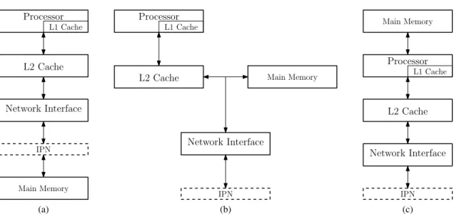
These types of memories complete the structure of a multiprocessor network node, which is slightly different in each one of the three memory configurations we already mentioned. The node configurations in Figure2.7 are just some examples for the most common memory systems, but are in no case unique. Other structures exist since which, for example, feature shared level 2 cache memories.
L2 Cache Processor L1 Cache Network Interface IPN Main Memory (a) L2 Cache Processor L1 Cache Network Interface IPN Main Memory (b) L2 Cache Processor L1 Cache Network Interface IPN Main Memory (c)
Figure 2.7: Common multiprocessor node structures. (a) UMA configuration. (b) NUMA config-uration. (c) Distributed memory configuration
2.1.2.2 Cache Coherence
Lets consider a situation where two different processes share the same parameter or variable, furthermore these processes are running concurrently in different cores of a multiprocessor system. During execution, this variable will be stored in the private caches of the two processors that are running these processes. If one of them modifies this variable then all other copies will have an incorrect value. In order for this not to happen and for the system to be able to maintain a coherent state, this change needs to be propagated to any other private caches that may need it. This mechanism is called cache coherence.
Several types of cache coherence protocols and schemes exist, many of which require the inclusion of specific hardware modules.
The simpler and most common cache coherence protocols are the write-trough protocol with updateand the write-trough protocol with invalidation. In the first, whenever a processor writes a new value in its private cache it will broadcast this value to all other cores in the system. Upon receiving one of these messages each processor will update the changed cache block with its new value if this block is present in their private cache. The second version of this protocol uses the concept of cache invalidation. Whenever a processor writes to a cache block, a broadcast is sent to notify other processors to invalidate their local copies of this block. The block is then written to the main memory so that other processes can access the updated version of the block but will only do it when they need it [18].
Many smaller multi-core systems with single-bus interconnections implement a coherence method called snooping. In this scheme each processor has an associated cache controller that observes all transactions made trough the communications bus. When a specific processor writes to a cache block for the first time, it makes a broadcast notifying other processors and the main
memory controller. Upon receiving this message they will invalidate their stored copies. From this moment on, the processor that made the write will be exclusive owner of this memory block and can write to it at will and without having to broadcast a notification to the other cores. If another processor wishes, it can make a request for this cache block. The main memory won’t be able to respond since its value has been invalidated, but the current owner of the block will observe this request and will respond with the correct value. At this moment the processor relinquishes exclusive control over the cache block, but since the main memory is also observing the shared bus it will also update the cache block with the new value, therefore it will now be able to respond to any other read requests. This process will repeat every time one of the processors writes to a shared cache block[18].
This arrangement reduces the number coherence messages used in comparison with the write-trough protocols. Still, they don’t improve much on the scalability of the cache coherence since a bus interconnect will easily become a bottleneck when we increase the number of cores in the processor.
Other coherence methodologies, such as directory based schemes and the IEEE’s Scalable Coherent Interface(SCI) standard, present more scalable coherency methods but still can’t keep up with the increase in number of cores in many-core platforms. In some cases, because of overhead created by coherence transactions, the increase in number of processing cores will lead to a drop in performance of the system[2][19].
2.1.2.3 Message Passing
Due to its poor scalability, the cache coherence methods that are used in multi-core architectures are not nearly as efficient when applied in many-core processors. An alternative to a dedicated coherence mechanism is to implement message passing.
In the message passing paradigm there is no shared memory space between different processes. Instead, when two processes need to share data, each one of them will have their own independent version of it and consistency can be achieved by cooperation, explicitly exchanging messages with the newest values. This means that coherence is no longer a hardware problem and is achieved trough software, shifting responsibility to the application designers.
Due to a much higher scalability, many-core development has been focusing on this technique instead of the cache coherence methods that were the norm in multi-core processors[2].
2.1.3 Examples of Many-Core Processor Architectures
In this section we’ll detail some of the most known, commercially available, many-core processor architectures. More attention is given to the TILE architecture, for being a trend setter in the field, and to the MPPA R architecture since it will be the target platform of this dissertation and for its focus on real-time systems.
2.1.3.1 The TeraFLOPS Processor Architecture
The TeraFLOPS many-core processor was developed within Intel’s Tera-Scale research program, and it features 80 cores, called processing engines, interconnected by an 8x10 2-D mesh network-on-chip. The entire chip was designed to operate with a clock frequency of 4 GHz, and it was manufactured with a 65 nm process.
It was designed with multimedia applications in mind, such as 3-D graphics and signal pro-cessing, it also had the objective of decreasing power consumption of the chip, particularly, by optimizing the power usage of the network routers[3].
Each network node contains two independent single-precision floating point multiply and ac-cumulate units, 3 KB of instruction memory, 2 KB of data memory, and a crossbar router with four mesosynchronous interfaces (Figure2.8).
Figure 2.8: Block diagram of the TeraFLOPS processor architecture [3]
The processor’s ISA defines a 96-bit VLIW that allows up to 8 operations to be issued each cycle. The instruction set is divided into 6 different types: Instructions to the floating-point units, data memory load and store instructions, NoC send and receive, the classic jump and branch instructions, synchronizations primitives(stall and wait-for-data), and sleep/wake instructions that can be used to lower power consumption dynamically. With exception of the instructions that target the floating-point units, most other instructions will execute in 1-2 cycles.
Each node features a 5-port 2-lane router that uses the wormhole switching technique. Each FLIT is divided into 6 control bits and 32 data bits, the minimum packet size is of two FLITs and there’s no restriction to its maximum size. The crossbar switch has a total bandwidth of 80 GB/s.
Power consumption in the router was decreased by significantly lowering the area and number of devices used for the crossbar switch.
This architecture implements a global mesosynchronous clocking scheme that aims to increase scalability of the processor. Only one clock source is used but phase asymmetries between the clock signal in the various cores are not compensated. This means that the routers had to be designed to work with phase-insensitive communications while operations inside each core work synchronous fashion.
This processor was always an experimental endeavor with the purpose of testing the feasibility of doing floating point operations on-chip and with realistic power consumption, and to be a benchmark to validate a switched network based design for highly parallel processors[4].
2.1.3.2 The Single-Chip Cloud Computer
The SCC was Intel’s second implementation of a networked many-core processor, it continues the work done by the TeraFLOPS team but with different goals. This architecture features 48 fully functional IA cores, arranged in 24 tiles, each with two Pentium P54C cores, 2 blocks of 256 KB L2 cache, 16 KB of memory to work as a message passing buffer, and the NoC router that is shared by both IA cores[4]. This processor was Intel’s successful attempt to implement the data-center computing model on die.
Figure 2.9: Block diagram of the Single-Chip Cloud Computer processor architecture [4]
The P54C is an augmented version of the P5 architecture that was used in the original Pentium processors, but it features a 64-bit instruction set and the necessary hooks to work in a dual SMP layout.
In the same vein as the TeraFLOPS processor, the SCC was designed to optimize power con-sumption and it implements both frequency and voltage scaling to do it. The mesosynchronous
clock scheme of the TeraFLOPS was omitted to increase power savings since it was considered by the SCC architects to be an overdesign. Instead a simpler scheme was used, where each tile can be running at an integer multiple of the clock source frequency that ranges from 1 GHZ to 2GHz and a clock-crossing FIFO is used to match different clock domains when needed. Clock gating is also implemented in this architecture, except within the routers.
As it happens in a lot of many-core architectures the classic hardware cache coherence mech-anisms used in SMP systems were dropped for a more scalable coherence through software. The SCC implements message-passing as a way to explicitly share information between the various cores, eliminating the common shared memory programming paradigm of SMPs.
The SCC’s router is heavily based of the TeraFLOPS’s router, and it implements the XY routing algorithm and the already common wormhole switching scheme. Its NoC provides a bandwidth of up to 2 TB/s, much more then one P54C core could ever us. This is the reason that each router is shared by a pair of cores, aside from this, each core inside a tile behaves as if they were in different tiles.
In addition to already mentioned frequency and voltage scaling, dynamic power management can be done by the system software, by turning off specific cores, tiles and even router ports.
This processor was Intel’s first implementation of a fully programmable networked many-core chip that can be used for application research.
2.1.3.3 The Tile Architecture
The tile processor was developed by Tilera and was heavily based on the MIT’s RAW processor that was designed by the company’s founders [20].
This architecture implements a 2D-mesh interconnect topology with five independent net-works, giving a total input/output bandwidth of 1.28 terabits per second (Tbps) for each core.
(a) (b)
Figure 2.10: (a) Block diagram of the TILE64 processor. (b) Array of tiles connected by the five NoCs [5].
The five networks are the User dynamic network (UDN), the I/O dynamic network (IDN), the static network (STN), the memory dynamic network (MDN) and the tile dynamic network (TDN). The two different types of classifications, static and dynamic, stem from the way data is transmitted through the networks. Dynamic networks maintain the order of messages between any two nodes, are flow controlled and guarantee reliable delivery. The static network doesn’t have a packet oriented format and it allows for static configuration of the routing decisions at each tile, it can be used, for example, to send am uninterrupted stream of data between any two cores. As for the dynamic networks, each one of them serves a different purpose. The UDN is a user level network, it allows processes and threads running in different cores to communicate with low latencies providing a faster way to exchange data then through shared memory. The IDN provides direct access to the I/O devices from any of the tiles. The MDN is used to access the shared off-chip DRAM. The TDN is also used for memory management, it implements a coherent shared memory environment by allowing direct cache-to-cache data transfers [5].
As it can be seen in Figure2.10(b), each tile is constituted by three main hardware blocks. The internal cache unit, the processing unit and a third switch unit that handles all the network traffic coming in and out of the five networks.
So that software developers can take advantage of the interconnect medium, Tilera provides a C library called iLib that implements a set of common communication primitives on the UDN. It includes socket-like streaming channels and an MPI for ad hoc messaging between cores. It also implements different types of communication channels such as, RAW channels that have lower latencies but are reduced to the available hardware buffering and Buffered channels that have a higher overhead but allow for unlimited amounts of buffering (Table2.1).
Table 2.1: Performance propieties of the various UDN communication methods
Mechanism Latency (Cycles) Bandwidth (Bytes/cycle) Buffering Ordering Raw channels 9 3.93 Hardware FIFO Buffered channels 150 1.25 Unlimited FIFO
2.1.3.4 The MPPA architecture
Kalray’s MPPA-256 processors have 256 integrated user cores, 32 system cores, and feature a clustered architecture where the several processing cores are arranged in smaller groups (clusters) connected via two independent NoCs. In the processor’s periphery there are four I/O subsystems, each one controlled by a quad-core symmetric multiprocessor (Figure2.11) [6].
The MPPA architecture is said to implement a heterogeneous multiprocessor, because groups processors are arranged in different ways to be able to provide different types of services.
Figure 2.11: Block diagram of the MPPA-256 processor [6]
Each of the compute clusters is constituted by 16 user cores or processing elements (PE), 1 extra system core or resource manager (RM), 2 independent routers for each NoC, a Debug and System Unit (DSU) and a 2MB shared memory (Figure2.12) [6].
The cluster’s local memory is shared by 17 VLIW cores without hardware cache coherence and it’s composed of 16 independent memory banks of 128Kb. Cache coherence inside the clusters is achieved by a simple software based method that the user programmer needs to pay attention to. This method will be described in more detail later on chapter4.
This memory is divided in two sides of 8 banks that service 12 bus masters, the RM core, the DSU, both NoC routers and 8 PE Core pairs.
The address mapping of the cluster’s memory can be configured as interleaved or as blocked. This has no functional implications but can have effects on performance. In the interleaved config-uration sequential addresses move between memory banks each 64 bytes, making this appropriate
for highly parallel applications because of the increased memory throughput. The blocked config-uration is better for time-critical applications because it reduces interference between cores since each memory bank is reserved for a single user core [21].
Figure 2.12: Block diagram of a MPPA cluster [6]
The MPPA cores implement a VLIW architecture with the purpose of exploiting instruction-level parallelism, since its instruction pipeline can launch up to five instructions per cycle. It has a single RISC-like ISA for both application code and system software.
A notable feature of this architecture is that it was developed with the objective of eliminating timing anomalies where a local worst-case execution does not contribute to the global worst-case, allowing a static timing analysis, of the processor and any application on it developed, to produce meaningful results [21].
As it was already mentioned, the various clusters are interconnected by the means of two independent networks, one is used for data transfers (D-NoC) and the other to exchange control information (C-NoC). Both networks share the same 2D-Torus Mesh topology and a wormhole switching style, but differ at the amount of buffering available at the cluster network interfaces [21]. Flit size is of 32-bit and the default payload data size is of 32 FLITs with a header size between 1 and 4 FLITs [22].
NoC traffic will be transparent to all but the destination node. Both networks provide guar-anteed services and reliable unicast, multicast and broadcast delivery but don’t implement an ac-knowledgment service at the packet source [23]. Hardware multicast/broadcast is only available
when targeting a group of clusters from the I/O subsystems. Multicast behavior between compute clusters is emulated by software with a series of unicast messages [22].
These networks can be accessed to from the exterior trough the NoCx extensions present in the four I/O subsystems, allowing the user to cascade multiple MPPA processors.
Since this will be the target platform of our dissertation, we will make a more in depth descrip-tion of the programming paradigms for software development on Kalray’s MPPA platform.
The MPPA SDK provides standard GNU C/C++ and GDB tools for compilation and debug-ging at cluster level. SMP Linux or RTEMS can run on the quad-core processors at the I/O sub-systems and a proprietary lightweight POSIX 1003.13 profile 52 (single process, multiple threads) Operating System called NodeOS on the compute clusters. Software development can be done with two fairly different programing paradigms, a cyclostatic dataflow C based language named ∑C and the more common POSIX-level programming approach[6].
In this dissertation we will focus on the POSIX-level programming. Its basic idea is that processes on the I/O subsystems will launch sub-processes on the cluster array and inside each cluster a different thread can be allocated to each one of the PE cores. The I/O subsystem spawns these sub-processes by using an adapted version ofposix_spawncalledmppa_spawn. In other hand the clusters can use the standardpthread_createcombined with
pthread_attr_setaffinity_npto start thread on specific PE cores. NodeOS also supports version 3.1 of the OpenMP standard, but maintains the 16 thread per-cluster limit [22].
The biggest difference to traditional POSIX programming and API is in the inter-process com-munication. IPC on the MPPA processors is done by working with special file descriptors, whose pathnames were created to identify the NoC resources used. The design of this IPC method was based on the component software model where processes are the components and file descriptors are the connectors. Multiple connectors are available to allow for various types of communication methods (Table2.2), detailed descriptions of the software connectors can be found at [22][24] and later in Chapter4.
Table 2.2: MPPAs IPC software connectors
Type Pathname Tx:Rx
Sync /mppa/sync/rx_nodes:cnoc_tag N:M
Portal /mppa/portal/rx_nodes:dnoc_tag N:M
Sampler /mppa/sampler/rx_nodes:dnoc_tag 1:N
RQueue /mppa/rqueue/rx_node:dnoc_tag/tx_nodes:cnoc_tag.msize N:1 Channel /mppa/channel/rx_node:dnoc_tag/tx_node:cnoc_tag 1:1
Operations with these connectors also follow the POSIX API. Common POSIX I/O func-tions, such asreadandwrite, were adapted to work with the MPPA’s NoCs and renamed with the mppa prefix. POSIX asynchronous I/O are also available for some of the connectors, and support for theSIGEV_CALLBACKis provided to install a callback function as notification for asynchronous operations.
The MPPA-256 processor can also be used as an hardware accelerator, for this the processor needs to be connected to the application host trough PCIe. Two special software connectors are provided to establish communication between the MPPA and the host machine (Table2.3).
Table 2.3: MPPAs PCIe software connectors
Type Pathname Tx:Rx
Buffer /mppa/buffer/rx_node#number/tx_node#number 1:1
MQueue /mppa/mqueue/rx_node#number/tx_node#number/mcount.tsize 1:1
In the context of this dissertation is important to reference the existing support to time critical applications. Every cluster is equipped with a DSU that contains a 64-bit TSC that is addressed in the local memory and can be accessed to by any core of the cluster. The whole processor is driven by a unique hardware clock which means these counter can be considered mesosynchronous. All counters can be initialized by a specific broadcast message in the C-NoC, which results in very small offsets between the counters of the various clusters. Each core supports a lightweight implementation of POSIX timers [21].
2.2
Clock Synchronization Algorithms
This section is a review of various clock synchronization algorithms that have been developed throughout the years.
These algorithms are relevant in distributed systems where a consistent time reference is an important feature. Since each process will have its own clock derived from a local crystal os-cillator it is impossible to guarantee that these have the same rate, and in systems without clock synchronization, even very small differences in frequency will eventually lead to a huge offset between two clocks.
All these algorithms share the same clock model, where each process has a counter that is incremented in an interrupt routine caused by an oscillator, this counter is the process clock. These clocks are assumed to be drift bounded by a constant value, ρ, that is known as the maximum drift rate between the clocks and real-time.
1− ρ ≤dC
dt ≤ 1 + ρ (2.1)
Clocks can then be divided in three types, fast, slow or perfect clocks (Figure2.13).
Figure 2.13: Graphical representation of clocks with diferent tick rates [7]
A given synchronization algorithm has to guarantee that, even for two clocks drifting in oppo-site directions, they will not ever differ by more than δ , this value is usually called the synchro-nization precision [7].
During this section we will present some relevant clock synchronization algorithms that have different degrees of distribution and that use assume different fault models as a consequence.
2.2.1 Probabilistic Clock Synchronization
Cristian kick started the clock synchronization approach where several clients contact a common time server and try to estimate the offset between their clocks.
Cristian’s algorithm is still interesting to this day because we can reduce the error of reading a remote clock to any desired amount, which eliminates the main problem of some of the algorithms that we will discuss later on this chapter, where the read error had the significantly effect on the worst-case skews. This is accomplished by letting the slaves make several attempts to read the master’s clock and calculating the maximum error at each attempt, the slave will only stop making time requests when the error reaches a desired value.
The way slaves calculate the maximum error is trough the RTD measurement technique and the read error is given by the following expression 2.2. Where ρ is the maximum drift between any non-faulty clock and Uminis the minimum message transit delay between master and slave [8].
ε= RT D(1 + 2ρ)− 2Umin (2.2)
As it can be understood from2.2, the error will decrease significantly with the decrease of the round trip delay. Therefore,"each node is allowed to read the master’s clock repeatedly until the round trip delay is such that the maximum read error is below a given threshold "[8].
This algorithm is not without his faults, and it is easy to realize that this clock reading scheme will drastically increase overhead when we try to lower the skew. Another possible problem is that theres a nonzero probability of a loss of synchronization which also increases when we decrease the target skew.
2.2.2 Network Time Protocol
NTP is one of the most used protocols on the Internet. It uses a hierarchical clock synchronization approach, where nodes can be both clients or servers and are divided into different strata accord-ing to the precision of their local clocks [7][25]. It also uses different algorithm for the various synchronization strata.
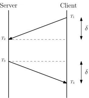
At its lowest level, NTP implements the approach proposed by Cristian [26], where multiple clients contact a common time server in order to synchronize their clocks with this special node. To do this, it tries to estimate the message delay so it can compensate it and correctly adjust his clock.
The method used to do this estimation is usually referenced as the round trip delay measure-ment. As an example, let’s consider a client and a time server that execute a round of the NTP algorithm (see Figure2.14). The client will start the round by sending a request to the server with a time stamp T1of the instant this message was sent. Upon receiving this request, the time server will record its time of arrival, T2, and send new message to the client containing T2 and a new the time stamp, T3, of the instant this response is sent to the client. When this second message is received, the client will have access to the three mentioned timestamps (T1, T2, T3) and to a forth time stamp, T4, of the moment this message was received. With these four time values the
Server
Client
T1 T2 T3 T4δ
δ
Figure 2.14: The NTP algorithm message exchange between a client and a time server
client can now estimate the communication delay (Expression2.3), and the offset (Expression2.4) between his local clock and the time server’s, assuming the propagation delay of both messages is symmetrical, i.e., T2− T1≈ T4− T3. θ=(T2− T1) + (T3− T4) 2 (2.3) δ =RT D 2 = (T4− T1)− (T3− T2) 2 (2.4)
2.2.3 Precision Time Protocol
The precision time protocol was standardized in IEEE-1588 and it’s defined as follows: "This standard defines a network protocol enabling accurate and precise synchroniza-tion of the real-time clocks of devices in networked distributed systems."[27]
This standard was developed to be used in control systems, usually in a industrial environment, because it supports sub-microsecond synchronization.
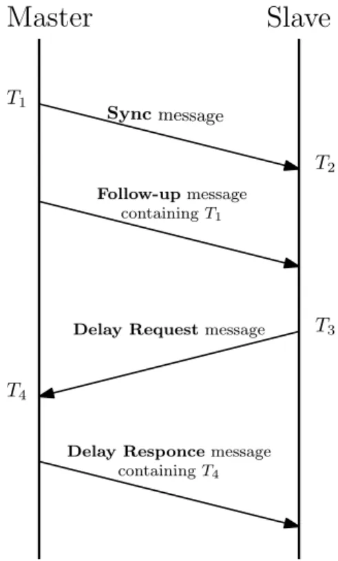
Just as NTP, it also proceeds to estimate the communication delay and the clock offset during the synchronization. The main differences between the two protocols are that in PTP all message transactions are started by a master and all timestamps are taken right after sending a message or with the help of dedicated hardware. These characteristics provide greater precision to PTP but increase the number of messages transactions that need to be done in each synchronization round. An example of a PTP synchronization round can be seen in Figure2.15. The round starts with the master sending a multicast sync message to all the existing slaves. All nodes that receive this message record its time of arrival (T2) and wait for a Follow up message containing the time stamp
in which the sync message was sent (T1). Upon receiving this message the slave will send a Delay Requestto the master and take its time stamp (T3), the master will answer this request by sending a message with the time stamp T4of the instant it received the Delay Request message.
Master
Slave
T1 T2 T3 T4 Sync message Follow-up message containing T1Delay Request message
Delay Responce message containing T4
Figure 2.15: PTP message sequence chart
By the end of a synchronization round the slave clock as all four timestamps needed to estimate the clock offset (Expression2.6) and message delay (Expression2.5) [28].
δ=(T2− T1) + (T4− T3)
2 (2.5)
θ= (T2− T1)− (T4− T3)
2 (2.6)
It is worth noting that even being a centralized, PTP can be made fault tolerant by implement-ing an election algorithm that chooses the node best fit to become the new master clock.
2.2.4 Distributed fault tolerant algorithms
This subset of algorithms are fully decentralized since all the processes equally contribute to gen-erate the time reference of the system, this means that there is no special process in charge of maintaining the system synchronized.
They were developed with a byzantine fault model in mind, mainly to solve the problem of two-facedclocks (Figure2.16). In which a process sends different clock values to different pro-cesses. Lamport and Melliar-Smith [29] proved that it was necessary to have at least 3m+ 1 clocks in order to tolerate m byzantine faults.
A B B 1 : 15 1 : 10 1 : 10 1 : 05 12 : 55 1 : 05
Figure 2.16: Example of a two faced clock at node A [8]
2.2.4.1 Convergence averaging algorithms
The main idea behind this type of algorithm, is to create a virtual global reference clock by cal-culating a fault tolerant average (FTA) with the clock values of all the processes that we wish to synchronize.
The creation of this reference is based on a periodic broadcast of local clock values to other processes in order for them to estimate the respective clock skews and then calculate the already mentioned averaging function [8].
In the algorithm proposed in [30], a process will broadcast its clock value periodically, it will also wait a limited amount of time, enough to guarantee it receives the broadcasts from all other non-faulty nodes in the network. After this period of time the process will calculate the already mentioned FTA in order to do the necessary corrections to its local clock. The function proposed in this algorithm, might be one of the most notable described in the literature, in which a process discards the m highest and lowest received clock values and then a common arithmetic average is applied to the remaining values. This function is able to tolerate a fixed number of m faulty clocks. The precision of these algorithms is greatly impacted by what is called the read error of a clock value. This error is caused by network delay jitter and processing time fluctuations. This is
important because upon the arrival of a message, the process needs to estimate the processing and network delays associated with said message in order to make the correct clock adjustments.
To implement these algorithms there is the need for a mechanism that will guarantee initial synchronization, because they were developed with a bounded clock skew in mind. There are several solutions for this problem including the one presented by Lundelius and Lynch in [30].
2.2.4.2 Interactive consistency algorithms
The underlying objective of these algorithms is to reach a consistent clock value that all processes can agree upon. It assures agreement on the clock value of a particular sender regardless of it being faulty or not [8].
Each process will broadcast their clock value periodically, upon receiving one of these mes-sages a process will relay it to all other processes, except to the one that sent the original message. This means that at the end of every synchronization round each process can hold up to N−1 clock values for the same process, N being the number of nodes in the system. After this, every process then chooses the median of these values, if the number of faulty nodes e less then a third of all pro-cesses then it is guaranteed that all non-faulty nodes will choose the same value for each sender, eliminating the problem of two-faced clocks [29].
Just like convergence algorithms its biggest limitation comes from the read error, but unlike them there is no need for initial synchronization for them to work correctly.
These algorithms can achieve greater precisions then their convergence counterparts for the same synchronization period but they are substantially more complex and have a higher overhead associated because they need more messages to be exchanged between the processes.
2.2.4.3 Convergence non-averaging algorithms
The best and most know example of this type of algorithm was presented by Srikanth and Toueg in [31].
In this algorithm, a resynchronization period needs to be established and every time a local clock goes trough this period the respective process broadcasts a message notifying other processes that is time to resynchronize. A process that receives this message wont immediately adjust its clock, instead, he will wait to receive at least m+ 1 messages from different processes where m is the number of byzantine faults the system can tolerate. This reassures the node that at least one non-faulty node is ready to resynchronize. When this happens, a process will adjust its clock to the next synchronization point with a small adjustment to compensate for the network delay. With enough rounds of the algorithm, all the clocks will eventually converge on the same time value.
This algorithm was presented in two different versions for the byzantine fault model. The first version assumes that authenticated messages are used for inter-process communication in order to guarantee that faulty nodes don’t change received messages before relaying then and can not create fake messages claiming they received them from another process. This Authenticated algorithm
if C= kP then
broadcast(init, round k); end if
if round k is accepted then . /*Received m + 1 (round k) messages*/ C= kP + α;
relay all the m+ 1 received messages to all; end if
Figure 2.17: Authenticated clock synchronization algorithm
can be seen in Figure2.17, where C is the local clock, P is the synchronization period and k is the index of the current synchronization round.
The second version implements a non-authenticated algorithm and it achieves the same degree of fault tolerance simulating authenticated broadcasts resorting to the broadcast primitive of Figure
2.18. The algorithm can then be reduced to the one presented in Figure2.19.
if Received (init, round k) from at least m+ 1 different processes then broadcast(echo, round k);
end if
if Received (echo, round k) from at least m+ 1 different processes then broadcast(echo, round k);
end if
if Received (echo, round k) from at least 2m+ 1 different processes then accept(round k);
end if
Figure 2.18: Broadcast primitive for the non-authenticated algorithm
if C= kP then
broadcast(init, round k); end if
if round k is accepted then C= kP + α;
end if
Figure 2.19: Non-Authenticated clock synchronization algorithm
A clear disadvantage of this variant is that it needs at least 2m+ 1 correct clocks to correctly synchronize all non-faulty processes, while the authenticated version only needs m+ 1.
Despite this, the Non-authenticated algorithm can be very interesting when considering sim-pler fault models, usually with crash or omission faults. For these models, the broadcast primitive can be simplified to Figure2.20.
if received (init, round k) from at least m+ 1 different processes then accept (round k);
broadcast(echo, round k); end if
if received (echo, round k) from any process then accept (round k);
end if
Figure 2.20: Broadcast primitive for the non-authenticated algorithm with crash/omission fault models
This new primitive considers systems where a process can be faulty because it sometimes fails to send-receive messages or because its clock is faulty in the sense that it violates the bounded drift model mentioned earlier in this chapter. Crashes and omissions are completely transparent to the algorithm, on the other hand it can only tolerate up to m faulty clocks.
Just like the averaging algorithms they also require an initial synchronization of the system to be done [8]. The proposed approach in this algorithm is to use a system reset, which means that when a broadcast reset message is sent by one of the processes all the others will set their clocks to zero.[31]
2.2.5 Gradient clock synchronization
The gradient propriety requires that "the skew between any two nodes’ logical clock be bounded by a non-decreasing function of the uncertainty in message delay" [32]. If we call this delay uncertainty the distance between two nodes, this means that if the implemented synchronization respects the gradient propriety than further apart nodes will have the same or larger clock skews then neighboring nodes. As we can see from Figure2.21, each node synchronizes only with their direct neighbors, eliminating the need for a root node or a more complex algorithm that would have the need for a much higher number of messages.
The gradient propriety for clock synchronization algorithms was first introduced in [32] with the motivation for it to be implemented in wireless sensor networks, specifically in multi-hop configurations to solve several existing problems, like data fusion or the implementation of a TDMA medium access control to minimize power consumption with synchronized wake up and sleep phases. In these situations only directly connected nodes need to be tightly synchronized and therefore gradient algorithms are a good solution.
Figure 2.21: Simplistic gradient clock synchronization protocol [9]
Several algorithms have been developed with this propriety in mind, all of them with a WSN deployment in mind, where the synchronization needs are only local and nodes can only commu-nicate directly with the neighboring nodes (Figure2.21).
Some implement a local convergence algorithm with a common FTA [9], others use the normal communication transactions in order to achieve synchronization and save battery power [33].
2.2.6 Converge-to-Max Algorithm
This protocol is one of the simplest distributed synchronization algorithms. Each process peri-odically broadcasts a message with a time stamp of its local clock. Upon receiving one of these messages a process will check if the received time stamp is larger than its local clock, if this is true, then it will adjust its clock to the received time stamp. Therefore, all clocks will eventually con-verge to the maximum clock value on the system[34]. This algorithm guarantees a monotonically increasing clock with discontinuities and it does not have the need for any initial synchronization mechanisms.
if timeout occurred then
broadcast(mi) with local clock time stamp Set timeout to φ
end if
if message mj received then
if m.timestamp > C then . /*C is the local clock*/
C= m.timestamp + α end if
end if
The converge-to-max technique is most commonly found in wireless sensor networks and in order to increase precision, it assumes MAC-layer time stamping, to eliminate network contention times from the synchronization error.
The main shortcoming of this algorithm is in the lack of inherent fault tolerance. A fault that increases the clock value of a process will seamlessly spread throughout the entire system. The proposed method to improve fault containment, is to make each node store a list of recent timestamps for each process so it can detect outliers, erratic clock values that do not correspond to the historical evolution of that process’s clock. These messages can then be discarded without disturbing the normal operation of the system.
2.2.7 Reachback Firefly Algorithm
The RFA protocol is based of a mathematical model that tries to represent the spontaneous syn-chronization of flashes made by firefly swarms in south-east Asia [35].
This algorithm was developed to synchronize simultaneous events in wireless sensor networks but it can be easily extended into a clock synchronization algorithm [36].
In the original model, each node will fire a periodic event, when another process observes this, it increases its phase shortening his own time to fire. This phase increase is calculated by a predetermined firing function. Let’s look at Figure2.23, that assumes a firing period of 100 time units, we can see that a node will immediately make a phase correction upon receiving a message that indicates the occurrence of a remote event.
Figure 2.23: Synchronization algorithm acording with the original model [10]
RFA makes some extensions to this model in order to account for real world issues like network latency or the lack instantaneous reaction times from the different processes [10].
The first addition made is the inclusion of message timestamping at the MAC-layer to elimi-nate the error created by network contention, allowing to correctly identify when the sender actu-ally fired.
The second extension is the reachback response of the algorithm. This notion was introduced because real processes cannot immediately respond to a message and these can reach out-of-order thanks to the effect of network delays. Therefore, instead of making an immediate phase adjust-ment when receiving a message, a node will make all adjustadjust-ments after the next firing instant,
![Figure 2.1: Bus connected multiprocessor [1]](https://thumb-eu.123doks.com/thumbv2/123dok_br/15187520.1016511/24.892.119.733.531.858/figure-bus-connected-multiprocessor.webp)
![Figure 2.4: NoC switching techniques. (a) Store-and-forward switching. (b) Whormhole switch- switch-ing [2]](https://thumb-eu.123doks.com/thumbv2/123dok_br/15187520.1016511/26.892.135.686.850.1052/figure-switching-techniques-store-forward-switching-whormhole-switch.webp)
![Figure 2.8: Block diagram of the TeraFLOPS processor architecture [3]](https://thumb-eu.123doks.com/thumbv2/123dok_br/15187520.1016511/31.892.274.657.664.900/figure-block-diagram-teraflops-processor-architecture.webp)
![Figure 2.9: Block diagram of the Single-Chip Cloud Computer processor architecture [4]](https://thumb-eu.123doks.com/thumbv2/123dok_br/15187520.1016511/32.892.206.648.690.939/figure-block-diagram-single-cloud-computer-processor-architecture.webp)
![Figure 2.11: Block diagram of the MPPA-256 processor [6]](https://thumb-eu.123doks.com/thumbv2/123dok_br/15187520.1016511/35.892.248.681.344.771/figure-block-diagram-mppa-processor.webp)
![Figure 2.12: Block diagram of a MPPA cluster [6]](https://thumb-eu.123doks.com/thumbv2/123dok_br/15187520.1016511/36.892.233.617.241.645/figure-block-diagram-mppa-cluster.webp)