Received: 25 May 2018 Accepted: 15 August 2018 Published: 07 September 2018 http://www.aimspress.com/journal/energy
Research article
Darrieus-type vertical axis rotary-wings with a new design approach
grounded in double-multiple streamtube performance prediction model
Nelson Batista1,2, Rui Melicio1,2,3,* and Victor Mendes1,4,5
1
Departmento de Física, Escola de Ciências e Tecnologia, Universidade de Évora, Portugal
2 ICT, Universidade de Évora, Portugal 3
IDMEC, Instituto Superior Técnico, Universidade de Lisboa, Lisboa, Portugal
4
Department of Electrical Engineering and Automation, Instituto Superior de Engenharia de Lisboa, Portugal
5
CISE, Electromechatronic Systems Research Centre, Universidade da Beira Interior, Portugal * Correspondence: Email: [email protected]; Tel: +351266745372; Fax: +351266745394. Abstract: Exploitation of wind energy with vertical axis rotary-wing has advantage over horizontal axis rotary-wing in areas where the wind is turbulent and unstable, i.e., with fast changes either in direction or velocity as normal happens in urban areas. The Darrieus-type vertical axis rotary-wing is experiencing a growth in interest for development and installation due to a growing interest in decentralizing energy conversion. This growth is expected to be in further augment in what concerns the way of the future, i.e., the smart grid environment. A problem linked with this Darrieus-type rotary-wing is the complexity in the performance prediction study, since the blades move around the rotor in 360°. An approach to the double-multiple streamtube performance prediction model for the vertical axis rotary-wing is offered in this paper, offering a flexible adapted tool when the airfoils lift and drag data are not available, or when more complex blade profiles of rotary-wings are in development. A new Darrieus-type vertical axis rotary-wing design is carried out with the approach offered, allowing for a self-start capable blade profile, having an adequate performance at high tip speed ratios. Several field tests are offered providing validation to the self-start, low noise and stable performance of the new rotary-wing design. Also, a modeling, control and simulation of grid integration are presented.
Keywords: Darrieus-type rotary-wing; wind turbine; double-multiple streamtube model; performance prediction; blade profile design; power electronics
Nomenclature: A: rotary-wing swept area; B1, B2, B3: blade slice airfoil; c: blade profile chord; c′:
blade profile chord as seen in path; Cd: blade drag coefficient; Cl: blade lift coefficient; Cn: normal
force coefficient; Cp: power coefficient; Ct: tangential force coefficient; Fn, Ft: normal and tangential
force, respectively; Fta: average tangential force; H, h: turbine and blade airfoil height, respectively; h:
blade airfoil height; h′: blade airfoil height as seen in path; i: index; n: number of turbine blades; P1,
P2, P3, P4, P5: blade movement path; Pt, Q: mechanical power and torque of the wind turbine,
respectively; Pg: electric power; R, R′: blade movement path radius; r: turbine radius; S1, S2: turbine
area slice; uds, uus: interference factor for the downstream and for the upstream, respectively; V∞:
undisturbed wind speed; Va: induced velocity; Vad, Vau: induced velocity in the downstream and in
the upstream, respectively; Vc: velocity component parallel to chord line; Ve: equilibrium velocity
between the downstream and the upstream; Vn: normal velocity component; Vr: rotor angular speed;
W: relative flow velocity; α: blade angle of attack; β: blade angle in relation to the vertical position; θ: blade azimuth angle around the rotor; ρ: air mass per unit of volume, fluid density; ω: rotor angular speed at the turbine; λ: tip speed ratio (TSR); ν, ν′: minimum and maximum blade axial angles in path P4
1. Introduction
The world population growth and social development drives the increase on energy utilization [1]. Decentralized electric energy production has been with a growing acceptance for the urban areas and is viewed as an important solution in the smarter grid context. The increase of renewable energy share in the mixed of electric power production is a fact responsible for augmenting the complexity of Energy Management Systems [2,3]. But also is a fact that renewable energy is the way of the future, regarding the concerns with sustainable development and climate change. Wind energy is in nowadays and must certain kept on being the main renewable energy share in the mixed of electric power production for the years to come. Although, in urban areas the exploitation of solar energy has more acceptance than wind energy, the need for environmentally sustainable housing, for instance, the new EU directives regarding sustainable development, drives an opportunity for looking at the exploitation of wind energy systems in buildings [4]. The EU 2030 Agenda for Sustainable Development has as a target to protect the planet from degradation, taking urgent action on climate change to support the needs of the present and future generations. But the wind speed is turbulent and unstable with fast changes in direction and velocity in urban areas, implying that in urban areas a vertical axis rotary-wing wind turbine (VAWT) has advantage over a horizontal axis rotary-wing wind turbine (HAWT) [5,6]. Hence, the opportunity for looking at the exploitation of wind energy systems in buildings must consider the VAWT as an important solution for R & D of convenient design [7]. The advantage of VAWT over HAWT is concerned with: insensitivity to yaw wind direction changes; smaller number of components; very low sound emissions; ability to generate energy from wind in skewed flows; three dimensional structural design, easier to integrate in urban architecture; ability to operate closer to the ground level. A modern VAWT can be divided in three basic types: Savonius [8], Darrieus [9] and H-rotor [10]. The Darrieus-type VAWT can be divided in two kinds of turbines: curved bladed turbine (or egg shaped turbine) and straight bladed turbine [11]. The Darrieus-type VAWT has a natural inability to self-start and several solutions have been presented to overcome this problem, such as: external electricity feed-in, guide-vanes [12], hybrid configuration of Savonius and Darrieus VAWT [13], blade pitch optimization [14], blade form
optimization [15], and specific blade profile design [16]. However, the use of extra components for overcoming the inability to self-start capability increases the complexity of the rotary-wing, leading to higher cost, including maintenance requirements, deriving lower sustainability. Additionally, in urban areas is essential to have a product with the lowest maintenance requireme nts as possible. The development of a blade profile form for a VAWT capable to self-start without extra components or external power and with a good performance at high tip speed ratio (TSR) is a complex and time-consuming task that tends to end with inconformity. If a VAWT needs to be self-starting, then the performance is compromised at high TSR [17–19]. This inconformity is a manifestation of the fact: If a VAWT is designed with too much effort for self-start without extra components or external power, then the performance at high TSR is deteriorated. A VAWT tending to exhibit a superior performance at high TSR tends to have inferior performance on self-start capability. Hence, the challenge is to achieve a design with an appropriated balance between the two desirable but seemingly incompatible features. This challenge motivates the work carried out in this paper.
This paper presents a development for a straight bladed Darrieus-type VAWT enhancement in urban areas in a smart grid environment. The development is carried out by a multidisciplinary work to study the aerodynamic behaviors, performance prediction, rotary-wing modeling and grid integration. Several VAWT performance prediction models have been developed [19], having strengths and weaknesses. The most widely used model is the double-multiple streamtube (DMS) [14,20] developed by I. Paraschivoiu and is the starting point for the approach offered in this paper. While the DMS model was developed taking in consideration the limited data available for the airfoils aerodynamic behavior, the approach offered considers the on-demand aerodynamic airfoil prediction of lift and drag. The air flow direction is considered as the main characteristic of the VAWT performance prediction, leading to a more dynamic prediction model and offering a faster tool for the development of complex shaped VAWT. The proposed approach also facilitates model integration in existing computational fluid dynamics and computer-aided design software. Several technics have been presented for VAWT performance prediction assisted by computational fluid dynamics [21–24], having some achieved a good concordance with wind tunnel field test data [25,26]. The paper is organized as follows. Section 2 presents the commonly used VAWT performance prediction models. Section 3 addresses the DMS model. Section 4 provides the novel approach to the DMS model. Section 5 presents a new Darrieus-type VAWT design, using the proposed approach. Section 6 presents the modeling and simulations results for the grid integration study. Finally, Section 7 outlines the conclusions.
2. Darrieus-type VAWT performance prediction models
The VAWT aerodynamic modeling has complexity due to the rotary-wings, i.e., the turbine blades movement around the rotor in a 360º. Indeed, VAWT performance prediction is far more complex than for HAWT. Several aerodynamic disturbances can be found in the VAWT operation, such as deep stall, dynamic stall and laminar separation bubbles. References [27–29] model the dynamic stall on VAWT, validating the results with particle image velocimetry data. Also, the flow of the wind as a skewed movement over the rooftop of a building must be considered, reference [30] addresses the consideration of feasibility analysis of a Darrieus VAWT installation on the rooftops. Despite the complexity of the aerodynamic behavior of Darrieus-type VAWT, several mathematical models have been developed [19] for performance prediction. These models have strengths and
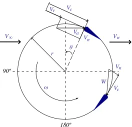
weaknesses and provide a more or less accurate prediction depending on the rotary-wing configuration, wind behavior and prediction time required. The most common used models can be divided into three categories: Vortex model, cascade model and blade element momentum (BEM) model. The vortex model [31,32] predicts the performance of VAWT by calculating the vorticity in the wake of the blades. The blades are substituted by vortex filaments whose strengths will be determined by the blade profile coefficients, relative flow velocity and angle of attack. Several modifications on this model have been presented, but the main disadvantage of the vortex model persists, i.e., the high use of computation time. In the cascade model [33–36] the VAWT blades are arranged in vanes called cascade and positioned in equal interspaces of the turbine perimeter divided by the number of blades. The aerodynamic properties of the blades are calculated independently taking in consideration the upwind and downwind sides of the rotor, the local Reynolds number and the local angle of attack. This model does not have convergence problems and provides good performance prediction in low and high TSR. However, like the vortex model, the cascade model requires a high use of computation time. BEM model combines blade element theory with basic momentum theory, studying the flow and behavior of the air on the blades and the involved forces. The BEM model can be further divided into: single streamtube model, multiple streamtube model and DMS model. The BEM single streamtube model is implemented as if the turbine is placed inside a single streamtube and the blades in the movement of rotation are assumed as presenting a behavior like an actuator disk. The effects outside the streamtube are assumed negligible and the wind speeds either in the upstream or in the downstream sides of the turbine are assumed as remaining with a constant value. These assumptions imply that this model is not expected to have a good turbine performance prediction, usually giving significant higher values, than those obtained from experimental data [19]. The BEM multiple streamtube model is a variation of the single streamtube model, where instead of having only one streamtube, there are several parallel and adjacent streamtubes independent from each other, having their own undisturbed, induced and wake velocities. Several modifications have been presented over the years, for instance, with the addition of: Drag forces, blade profile geometry, turbine solidity, curvature flow. However, the performance prediction that is to be expected is still far from the one obtained with experimental values [19]. The DMS model is a variation of the multiple streamtube model in which the actuator disc is divided in two half cycles in tandem, modeling the upstream and the downstream sides of the rotor. This model has received some improvements over the years and provides a good performance for most predictions and comparatively has a small use computer resources in what regards the central processing uni time [19]. But, eventually, the model may suffer from convergence problems for high TSR and high solidity turbines. So, the DMS model serves as only the basis for our novel approach to the Darrieus-type VAWT performance prediction. The most common used models are from the performance prediction categories of vortex model, cascade model or blade element momentum (BEM) model. These models share the same aerodynamic principles. A flow velocities diagram for a lift-type VAWT is illustrated in Figure 1 [19].
Figure 1. Flow velocities diagram of a lift-type VAWT.
The undisturbed wind velocity 𝑉∞ reaches the rotary-wing blade profile as an induced velocity
𝑉𝑎. The induced velocity due to the rotor angular speed at the rotary-wing 𝑉𝑟, i.e., due to the blade in movement around the rotor, is given by [19]:
𝑉𝑟 = 𝜔 𝑟 (1)
The blade is influenced by the contribution of the induced velocity 𝑉𝑎 and by the induced velocity due to the rotor angular speed at the rotary-wing 𝑉𝑟 in a resulting chordal velocity (velocity parallel to the chord line of the blade profile) 𝑉𝑐, which is given by [19]:
𝑉𝑐 = 𝜆𝑉𝑎 + 𝑉𝑎𝑐𝑜𝑠𝜃 (2)
Where 𝜃 is the blade azimuth angle around the rotor and 𝜆 is the TSR. The induced velocity 𝑉𝑎 contributes to the normal velocity, velocity in a radial direction in relation to the center of the rotor, 𝑉𝑛 given by [19]:
𝑉𝑛 = 𝑉𝑎sin𝜃 (3)
The relative flow velocity 𝑊 is given by [19]: 𝑊 = 𝑉𝑐2+ 𝑉
𝑛2 = 𝑉𝑎 1 + 2𝜆cos𝜃 + 𝜆2 (4)
The wind flow reaches the blade at an angle of attack 𝛼 that depends on 𝑊 and 𝜃. The angle of attack 𝛼 is given by [19]:
𝛼 = tan−1 𝑉𝑛
𝑉𝑐 = tan
−1 sin𝜃
𝑟𝜔 /𝑉𝑎+cos𝜃 (5)
Considering the force acting on the blade, the tangential force coefficient 𝐶𝑡 and normal force coefficient 𝐶𝑛 in function of the lift coefficient 𝐶𝑙, drag coefficient 𝐶𝑑 and of the angle of attack 𝛼 are given by [19]: 𝐶𝑡 = 𝐶𝑙sin𝛼 − 𝐶𝑑cos𝛼 (6) 𝐶𝑛 = 𝐶𝑙cos𝛼 + 𝐶𝑑sin𝛼 (7) 90º 180º ∞ V θ r ω V W Vc Vn c n V Vr Va Vw
The tangential force 𝐹𝑡 and normal force 𝐹𝑛 are given by [19]: 𝐹𝑡 = 1 2𝐶𝑡𝜌 𝑐 𝐻 𝑊 2 (8) 𝐹𝑛 = 1 2𝐶𝑛𝜌 𝑐 𝐻 𝑊 2 (9)
Where 𝜌 is the fluid density, 𝑐 is the blade profile chord, 𝐻 is the turbine height. The average tangential force 𝐹ta in function of the tangential force 𝐹𝑡 around the rotor and the azimuth angle 𝜃 is
given by [19]:
𝐹ta = 1
2𝜋 𝐹𝑡 𝜃 𝑑𝜃 2𝜋
0 (10)
The turbine overall torque 𝑄 is given by [19]:
𝑄 = 𝑛 𝐹ta 𝑟 (11)
Where 𝑛 is the number of blades of the rotary-wing. The turbine overall power is given by [19]:
𝑃𝑡 = 𝑄 𝜔 (12)
The power coefficient 𝐶𝑃 is the ratio between the rotary-wing power output and the power available in the wind given by [19]:
𝐶𝑃 = 𝑃𝑡
1/2𝜌 𝑉∞3𝐴 = 2 𝑛 𝐹ta 𝜔
𝜌 𝑉∞3𝐻 𝑟 (13)
3. DMS model
The actuator disc is divided in two actuator discs, each of them with their own induced velocity. A DMS model diagram is shown in Figure 2.
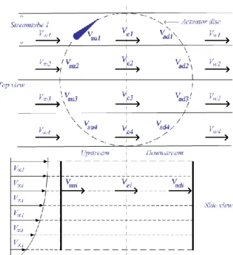
Figure 2. Double-multiple streamtube model diagram.
The induced velocity decreases along the axial streamtube direction, so the induced velocity in the upstream 𝑉aui is less than the undisturbed wind velocity 𝑉∞𝑖 that arrives to the streamtube 𝑖. Between the upstream and the downstream there is an equilibrium induced velocity 𝑉ei that is less than 𝑉aui. The induced velocity in the downstream 𝑉𝑎𝑑𝑖 is less than 𝑉ei. The induced velocity in the upstream 𝑉aui is given by [19]:
𝑉aui = 𝑉∞𝑖 𝑢usi (14)
Where 𝑢usi is the interference factor for the upstream which is less than 1.
The equilibrium induced velocity between the upstream and the downstream 𝑉𝑒𝑖 is influenced by the wake velocity of the upstream, which is given by [19]:
𝑉𝑒𝑖 = 𝑉∞𝑖 2𝑉𝑉aui
∞𝑖 − 1 = 𝑉∞𝑖 2𝑢usi− 1 (15)
The induced velocity in the downstream 𝑉adi is given by [19]:
𝑉adi= 𝑢dsi𝑉𝑒𝑖 = 𝑢dsi(2𝑢usi− 1)𝑉∞𝑖 (16)
Where 𝑢dsi is the interference factor for the downstream given by [19]: 𝑢dsi =𝑉adi
𝑉𝑒𝑖 (17)
The aerodynamic behavior of the blades in the upstream side of the rotary-wing will influence the induced velocity on the blades in the downstream side. The undisturbed wind velocity 𝑉∞𝑖 is defined by the wind velocity profile and increases along the rotary-wing height.
The torque and power coefficient of the VAWT are determined by integrating the aerodynamic behaviors of the several streamtubes.
For the rotary-wings that differ from the straight bladed Darrieus-type VAWT, the local blades radius and inclination are adjusted in relation to the blade form in the streamtube that is under evaluation and will influence the airfoil aerodynamic properties. This is the case of the performance evaluation for the egg shaped Darrieus-type VAWT.
The need to develop new airfoils and to have more accurate airfoil aerodynamic coefficients associated to the Reynolds numbers under evaluation, leaded to the use of a software application to analyze the blade profiles behavior. For this task the JavaFoil [37] is selected, which is a fast processing computational tool with a validated accuracy. The computational tool receives as input data the airfoil coordinates, angle of attack and Reynolds number. The tool analyses the aerodynamic conditions and delivers the airfoil coefficients lift, drag or momentum coefficient. One other important advantage of the JavaFoil computational tool is the ability to automate the tasks with a scripting language and to deliver the output data in the form of tabled data in files, which is easier to integrate with other tools.
A computational model was developed using Advanced Business Application Programming (ABAP), which is a high-level programming language created by SAP SE. This high-level programming language is optimized for enterprise applications to work with large amounts of data, selecting and analyzing data. Since the aerodynamic coefficients will be calculated on demand, there is the need to save the resulting data in a database. Several analyses will be made for each streamtube upstream and downstream side, leading to thousands of table rows to be saved and analyzed.
For the DMS model, first the rotary-wing is divided in streamtubes, and then an interference factor 𝑢us is selected for the upstream side of a streamtube. By having the undisturbed wind velocity 𝑉∞, the rotor angular speed 𝜔, blade radius 𝑟, blade angle of attack 𝛼, and local Reynolds number are
found. By interacting with the JavaFoil computational tool and with the calculated data and airfoil coordinates, the lift and drag coefficients can be found. The blade force is then computed using the interference factor and using the common aerodynamic equations previously presented. The two resulting forces are compared and a new interference factor 𝑢us is calculated until a convergence with an error of 10−4 is reached. By knowing the interference factor it is now possible to calculate the final torque 𝑄 and the power coefficient 𝐶𝑃. An interference factor 𝑢ds for the downstream streamtube side is then selected and the process starts again for every streamtube.
The power coefficient prediction as function of the TSR for an H-Rotor Darrieus-type rotary-wing for a wind speed value of 12 m/s and a turbine solidity value of 0.07 using the DMS model is shown in Figure 3. Two different airfoils were considered: A symmetrical airfoil (NACA0018) and an asymmetrical airfoil (NACA4418).
Figure 3. Power coefficient prediction as function of the TSR. 4. Novel approach to the DMS model
A novel approach to the DMS model was developed. Instead of directly integrating the several streamtubes performance as in the DMS, in the novel approach the rotary-wing is sliced in divisions parallel to the wind flow path and each slice is treated as an independent rotary-wing, and only afterwards the resulting slices performance data are integrated. The main difference and the novelty in comparison with the classical DMS model is that, before the slice performance data is calculated, the blade profile design and movement path inside the slice is analyzed for each angle. By dividing the rotary-wing in several slices, and analyzing the blade behavior in the slice as the way the wind flow will encounter the blade, is highly advantageous. Hence, with the novel approach proposed in this paper, it will be possible to have a more accurate analysis of complex blade form designs in VAWT, in order to study several rotary-wing installation positions and the performance in a skewed flow. Moreover, it can be easily integrated in existing CFD and CAD software, augmenting its interest and value.
To explain and illustrate the main concepts, two performance prediction cases are presented: A Darrieus-type VAWT with V shaped blades (Figure 4) and an H-Rotor VAWT in skewed flow (Figure 5).
Figure 4. Novel approach to the DMS model in a V shaped Darrieus-type VAWT.
Figure 5. Novel approach to the DMS model in an H-Rotor VAWT influenced by a wind in skewed flow.
Figure 4 illustrates the first case were the rotary-wing is going to be sliced parallel to the undisturbed wind velocity 𝑉∞ flow path. The smaller the difference between the slices, the more accurate will be the prediction. One example of a slice is represented as slice 𝑆1, made in the middle of the rotary-wing. After the slice is made, the behavior of the blade is analyzed as it is found by the wind flow in its path. The blade profile that is found is the airfoil 𝐵1 which is the same airfoil of the blade has a movement that follows a circular path 𝑃1 with radius 𝑅 . With this analysis, the computational model presented in the previously is used, by considering a turbine height equal to the height between slices. Another example of a slice is 𝑆2. Again, the slice is analyzed for the blade airfoil and the path as it is found by the wind flow in its movement. The blade follows another circular path 𝑃2 with a different radius 𝑅′. The airfoil in this slice is different from the one on the blade, since it has a higher airfoil height. It can be seen that the height ′ of this blade is related to the angle 𝛽 of the blade and the blade airfoil height , given by:
′=
cos 𝛽 (18)
The airfoil form in slice 𝑆2 can also be analyzed by CAD software, for instance. Now that the airfoil form is known, its aerodynamic behavior can be predicted with the JavaFoil tool in cooperation with the DMS model computation tool. By analyzing each slice as an independent rotary-wing, the aerodynamic behavior of the rotary-wing and its blade shape can be studied in more detail. Moreover, it is now simpler to integrate the DMS model into existing CFD and CAD software.
Figure 5 illustrates the second case were an H-Rotor VAWT influenced by a wind in skewed flow, which. The common rotary-wing blade path is represented as circular path 𝑃1 with radius 𝑅. By analyzing the slice in the middle of the rotary-wing, it can be seen that the wind flow does not find a circular path but instead an elliptical shaped path 𝑃3 where the minor radius is equal to 𝑅 and the major radius is equal to 𝑅′. In this slice the blade profile has different shapes depending on the blade angle in evaluation. On one hand, when the blade is close to the major radius its shape is the same as the shape in 𝑆2 of the previous case and can be found in the same way using the angle 𝛽, which is the angle between the position parallel to the rotary-wing position and the position of the undisturbed wind velocity 𝑉∞ flow path. On the other hand, when the blade is close to the minor
radius its airfoil 𝐵3 has the same height of the blade airfoil but with a different chord size 𝑐′ that is related to the angle 𝛽 and the blade airfoil chord 𝑐 given by:
𝑐′= 𝑐
cos 𝛽 (19)
In this case not all the blade angles around the rotary-wing are analyzed for certain slices. The slice in the top of the rotary-wing with the path 𝑃4 is an example of that, since only the positions of the blade when it is positioned between angles 𝜐 and 𝜐′ are analyzed. A remark must be made in these situations when analyzing the blade aerodynamic behavior in a certain position: it must be known if the wind flow comes from an upstream streamtube or not. If not, the wind flow analysis should be made as if the blade is in the upstream side of the rotor, even when the slice is in the bottom of the rotary-wing, as in path 𝑃5.
Figures 6 and 7 present the power coefficient 𝐶𝑝 vector for several slices along the V shaped blade Darrieus-type VAWT with the profile NACA0018, respectively at TSR value equal to 3 and equal to 11.
Figure 6. Power coefficient vectors for several slices at TSR equal to 3, considering the novel approach.
Figure 7. Power coefficient vectors for several slices at TSR equal to 11, considering the novel approach.
The higher contribution for the movement of the blades comes from the extremities closer to the axis, when the TSR is equal to 3, but when the TSR is equal to 11 the major contribution comes from the mid part of the rotary-wing, particularly where the wind flow finds the NACA0018 (Slice 𝑆1 from Figure 4).
5. New Darrieus-type VAWT design
By applying the novel approach presented in the previous section, a new Darrieus-type VAWT was developed. In this section, the respective form and its main advantages are going to be presented.
Figure 8 presents a new developed rotary-wing patented design [38], where each blade is constituted by three parts: A main body (represented as 1) and two blade ends (represented as 2). The blade ends were specially designed to work as new lift-capable blades that extend the main blade body. These blade ends are placed in an angle to the inside of the rotor.
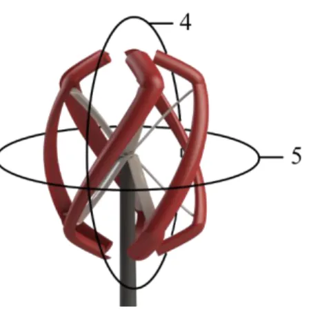
The blades were developed with the innovative blade profile called EN0005 [39]. With the novel blades configuration, the rotary-wing can take full advantage of the energy flow wherever it reaches the turbine in any vertical or horizontal angle in relation to the rotor position. These wind flow vertical and horizontal planes are represented by 4 and 5 respectively in Figure 9.
Figure 9. Wind flow reaching the new Darrieus-type VAWT in vertical or horizontal planes. The blades have a helical shape to decrease vibrations on the pole when the rotary-wing is rotating. The number of blades was chosen to facilitate the rotary-wing self-start and at the same time reduce the vibrations on the pole when it is rotating. With the blades ends positioned to the inside of the rotor, a drag is generated due to the augmented blade profile height, leading to an improved self-start capability. Moreover, when the rotary-wing is rotating, the blade ends lead to an increase of lift forces augmenting the turbine blade revolutions stability, as a result of the orientation of the normal forces exerted on the body of the blade ends, especially at high rotation.
The new Darrieus-type VAWT design under wind tunnel tests is shown in Figure 10.
Figure 10. New Darrieus-type VAWT design prototype.
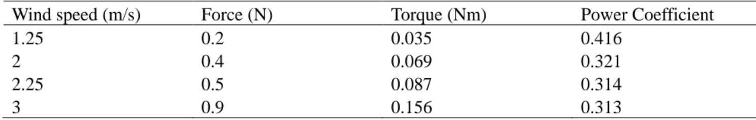
The field tests were carried out in urban and wind tunnel controlled environment scenarios. The tests were performed to assess the rotary-wing behavior. The behavior at low wind speed is assessed with emphasis in the self-start ability, the torque measurements were taken when the rotary-wing
reaches the first rotation, starting from the null angular speed. The torque is shown in Table 1. Table 1. Field test self-start torque.
Wind speed (m/s) Force (N) Torque (Nm) Power Coefficient
1.25 0.2 0.035 0.416
2 0.4 0.069 0.321
2.25 0.5 0.087 0.314
3 0.9 0.156 0.313
The collected field tests data allows to conclude that the Darrieus VAWT design has self-start without extra components at the wind velocities of 1.25 m/s.
The vibrations generated by the rotary-wing in urban scenario were tested and two examples of the assessed data are shown in Figures 11 and 12, presenting the vibrations on the pole near the generator during a fast variation of the wind velocity from 1.25 m/s to 2.5 m/s and from 5 m/s to 8 m/s, respectively.
Figure 11. Vibration field test for wind speeds from 1.25 m/s to 2.5 m/s.
An important feature for urban areas installation is the low noise generation of a rotary-wing. The presented rotary-wing gives a virtually inaudible noise in accordance with the field test shown Table 2.
Table 2. Field test noise generation. Wind speed Distance to rotary-wing 2.5 m/s 5.0 m/s 0 m (rotary-wing stoped) 42.5 dB 44.2 dB 0 m 42.5 dB 44.2 dB 1 m 42.5 dB 44.2 dB 2 m 42.5 dB 44.2 dB 3 m 42.5 dB 44.2 dB
Wind tunnel controlled environment was carried out for wind speeds up to 25 m/s, without showing any abnormal vibration on the blades neither on the pole. The prototype components did not reveal any problem during the exposed stress test. The prototype rotor speed at different wind speeds is shown in Figure 13.
Figure 13. Prototype rotor speed at different wind speeds. 6. Grid integration: Modeling, control and simulation
The new Darries-type rotary-wing prototype was developed with the innovative blade profile called EN0005 [39] offering self-start capabilities and a good performance at high TSR. A brief grid integration study is provided in addition to the self-start capabilities and enhancement performance of the Darrieus-type rotary-wing. This study describes the control and is about a simulation of the currents injected into the grid.
6.1. Modeling and control
The mechanical power of the turbine is given by [40,41]: 𝑃𝑡 =1
2𝜌 AV∞3𝐶𝑃 (20)
The drive train model is based on the second law of Newton, given by [40]:
𝑑𝜔 dt =
1
𝐽 (𝑄 − 𝑇𝑔) (21)
The permanent magnet synchronous generator modeling is given by [40]:
di𝑑 dt = 1 𝐿𝑑 𝑢𝑑 + 𝑝𝑙 𝜔𝑔 𝐿𝑞 𝑖𝑞 − 𝑅𝑑 𝑖𝑑 (22) di𝑞 dt = 1 𝐿𝑞 𝑢𝑞− 𝑝𝑙 𝜔𝑔(𝐿𝑑 𝑖𝑑 + 𝑀 𝑖𝑓) − 𝑅𝑞 𝑖𝑞 (23)
The electric power is given by:
𝑃𝑔 = [𝑢𝑑 𝑢𝑞 𝑢𝑓] [𝑖𝑑 𝑖𝑞 𝑖𝑓] 𝑇 (24)
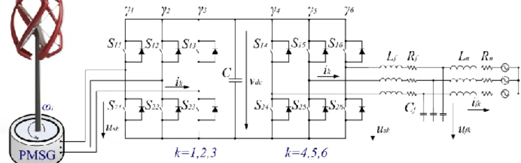
A two-level converter is considered, as in [42,43], having with six unidirectional commanded IGBTs used as a rectifier and with the same number of unidirectional commanded IGBTs used as an inverter. The configuration of the wind energy system is shown in Figure 14.
Figure 14. Wind energy system with the two-level converter.
A three-phase active symmetrical circuit in series models the electric grid. The state equation for electric currents injected into the electric grid are given by:
difj dt =
1
𝐿𝑛(𝑢fj− 𝑅𝑛 𝑖fj− 𝑢𝑗) (25)
Power converters are variable structure systems, because of the on/off switching of their IGBTs. Pulse width modulation by space vector modulation associated with sliding mode is used for controlling the converters. Sliding mode control strategy [43,44] presents attractive features such as robustness to parametric uncertainties of the rotary-wing and the generator, as well as to electric grid disturbances.
6.2. Simulation results
The power coefficient as a function of the TSR for the new Darrieus-type VAWT, an H-Rotor with airfoil NACA0012 and an H-Rotor with airfoil NACA0018 is shown in Figure 15.
Figure 15. Power coefficient as a function of the new Darrieus-type VAWT, an H-Rotor with airfoil NACA0012 and an H-Rotor with airfoil NACA0018.
The lift and drag coefficients of the airfoils EN0005, NACA0012 and NACA0018 calculated from Javafoil are shown in Figures 16 and 17.
Figure 16. Lift coefficient of the airfoils EN0005, NACA0012 and NACA0018.
Figure 15 shows that the EN0005 airfoil provides a significantly better performance in comparison with the other two airfoils, NACA0012 and NACA0018, that are commonly considered to have high performance at high TSR. A data for a comparison between the airfoils are shown in Table 3.
Table 3. Maximum power coefficient and corresponding TSR for the airfoils EN0005, NACA0012 and NACA0018.
Airfoil CPmax TSR
EN0005 0.373 7.278
NACA0012 0.325 6.396
NACA0018 0.336 6.645
The mechanical power of the rotary-wing, the electric power of the generator and the difference between these two powers, i.e., the accelerating power, are shown in Figure 18.
Figure 18. Mechanical, electric and accelerating power.
The wind energy system considered has a rated electric power of 10 kW. A wind speed upstream of the rotor given by a ramp increase was considered, taking 2.5 s between the 4.5 and 25 m/s the time horizon is 4 s. The rotor speed of the rotary-wing and the currents injected into the electric grid are respectively shown in Figures 19 and 20.
Figure 20. Currents injected into the electric grid.
Figure 20 is shown that the currents injected into the electric grid has a normal behavior as expected, which is important for the performance and interest of the proposed Darrieus -type rotary-wing with the EN0005 airfoil.
7. Conclusion
This paper is focused on the study and development of new Darrieus-type vertical axis rotary-wings design and along with the presentation of the VAWT performance prediction models and the description of the classic DMS model a novel approach is introduced to the DMS model. The novel approach is concerned with the description of rotary-wing considered modeled in slices parallel to the wind flow, i.e., in each slice the form and behavior of the blade as is found by the wind flow is modeled. This approach in characterized by simplifying the development of the blade design of complex Darrieus-type vertical axis rotary-wings. An instance of a development with the novel DMS approach is carried out for a novel rotary-wing configured with the innovative blade profile design EN0005. This blade design gives the rotary-wing the ability to self-start, offering at the same time a good performance at high TSR. This rotary-wing is used as a prototype for carrying out field tests to conclude about the ability achieved with the approach. The field tests carried out allow to conclude that the prototype, as expected, has self-start capability without the need for extra components at the wind speed of 1.25 m/s. Also, the field tests are in accordance with the conclusion that the movement is a stable rotation, although with a small vibration in the pole and with almost virtually inaudible noise. A grid integration simulation is presented to assess behavior of the interconnection of the proposed Darrieus-type vertical axis rotary-wings design with the EN0005 airfoil.
Acknowledgments
This work is funded by: European Union through the European Regional Development Fund, included in the COMPETE 2020 (Operational Program Competitiveness and Internationalization) through the ICT project (UID/GEO/04683/2013) with the reference POCI010145FEDER007690; Portuguese Funds through the Foundation for Science and Technology-FCT under the project
LAETA, reference UID/EMS/50022/2013; Portuguese Foundation for Science and Technology (FCT) under Project UID/EEA/04131/2013.
Conflict of interest
The authors declare no conflict of interest. References
1. Brunner H, Hirz M, Hirschberg W, et al. (2018) Evaluation of various means of transport for urban areas. Energy Sustain Soc 8: 9.
2. Akram U, Khalid M, Shafiq S (2018) An improved optimal sizing methodology for future autonomous residential smart power systems. IEEE Access 6: 5986–6000.
3. Shakeri M, Shayestegan M, Reza SMS, et al. (2018) Implementation of a novel home energy management system (HEMS) architecture with solar photovoltaic system as supplementary source. Renew Energ 125: 108–120.
4. Batista NC, Melicio R, Mendes VMF (2014) Layered Smart Grid architecture approach and field tests by ZigBee technology. Energ Convers Manage 88: 49–59.
5. Eriksson S, Bernhoff H, Leijon M (2006) Evaluation of different turbine concepts for wind power. Renew Sust Energ Rev 12: 1419–1434.
6. Arab A, Javadi M, Anbarsooz M, et al. (2017) A numerical study on the aerodynamic performance and the self-starting characteristics of a Darrieus wind turbine considering its moment of inertia. Renew Energ 107: 298–311.
7. Batista NC, Melicio R, Mendes VMF, et al. (2015) On a self-start Darrieus wind turbine: Blade design and field tests. Renew Sust Energ Rev 52: 508–522.
8. Krajacic G, Duic N, Carvalho MG (2011) How to achieve a 100% res electricity supply for Portugal? Appl Energ 88: 508–517.
9. Kumbernuss J, Jian C, Wang J, et al. (2012) A novel magnetic levitated bearing system for vertical axis wind turbines (VAWT). Appl Energ 90: 148–153.
10. Eriksson S, Bernhoff H, Leijon M (2008) Evaluation of different turbine concepts for wind power. Renew Sust Energ Rev 12: 1419–1434.
11. Shigetomi A, Murai Y, Tasaka Y, et al. (2011) Interactive flow field around two Savonius turbines. Renew Energ 36: 536–545.
12. Castelli MR, Englaro A, Benini E (2011) The Darrieus wind turbine: Proposal for a new performance prediction model based on CFD. Energy 36: 4919–4934.
13. Chong WT, Naghavi MS, Poh SC, et al. (2011) Techno-economic analysis of a wind—solar hybrid renewable energy system with rainwater collection feature for urban high-rise application.
Appl Energ 88: 4067–4077.
14. Eriksson S, Bernhoff H (2011) Loss evaluation and design optimisation for direct driven permanent magnet synchronous generators for wind power. Appl Energ 88: 265–271.
15. Takao M, Kuma H, Maeda T, et al. (2009) A straight-bladed vertical axis wind turbine with a directed guide vane row-effect of guide vane geometry on the performance. J Therm Sci 18: 54–57. 16. Gupta R, Biswas A, Sharma KK (2008) Comparative study of a three-bucket Savonius rotor with
17. Jesch LF, Walton D (1980) Reynolds number effects on the aerodynamic performance of a vertical axis wind turbine. Proc 3rd International Symposium on Wind Energy Systems, 26–29. 18. Hill N, Dominy R, Ingram G, et al. (2009) Darrieus turbines: The physics of self-starting. Proc
Inst Mech Eng A J Power Energy 223: 21–29.
19. Paraschivoiu I (2009) Wind turbine design with emphasis on Darrieus concept. Canada:
Polytechnic International Press, Bibliothèque et Archives Nationales du Québec.
20. Bhatta P, Paluszek MA, Mueller JB (2008) Individual blade pitch and camber control for vertical axis wind turbines. Proc 7th World Wind Energy Conference, Kingston, Canada, 1–10. 21. Zamani M, Maghrebi MJ, Varedi SR (2016) Starting torque improvement using J-shaped
straight-bladed Darrieus vertical axis wind turbine by means of numerical simulation. Renew
Energ 95: 109–126.
22. Bedon G, De Betta S, Benini E (2016) Performance-optimized airfoil for Darrieus wind turbines.
Renew Energ 94: 328–340.
23. Ferreira CS, van Kuik G, van Bussel G, et al. (2009) Visualization by PIV of dynamic stall on a vertical axis wind turbine. Exp Fluids 46: 97–108.
24. Ferreira C, Dixon K, Hofemann C, et al. (2009) The VAWT in skew: Stereo-PIV and vortex modeling. 47th AIAA Aerospace Sciences Meeting Including The New Horizons Forum and
Aerospace Exposition, 1–25.
25. Arpino F, Cortellessa G, Dell’Isola M, et al. (2017) CFD simulations of power coefficients for an innovative Darrieus style vertical axis wind turbine with auxiliary straight blades. 35th UIT
Heat Transfer Conference 963: 1–8.
26. Scungio M, Arpino F, Focanti V, et al. (2016) Wind tunnel testing of scaled models of a newly developed Darrieus-style vertical axis wind turbine with auxiliary straight blades. Energ
Convers Manage 130: 60–70.
27. Dominy R, Lunt P, Bickerdyke A, et al. (2007) Self-starting capability of a Darrieus turbine. P I
Mech Eng A-J Pow 221: 111–120.
28. Islam M, Ting DSK, Fartaj A (2008) Aerodynamic models for Darrieus-type straight-bladed vertical axis wind turbines. Renew Sust Energ Rev 12: 1087–1109.
29. Ponta FL, Seminara JJ, Otero AD (2007) On the aerodynamics of variable-geometry oval-trajectory Darrieus wind turbines. Renew Energ 32: 35–56.
30. Ferreira CS, van Kuik G, van Bussel G, et al. (2009) Visualization by PIV of dynamic stall on a vertical axis wind turbine. Exp Fluids 46: 97–108.
31. Ferreira CJS, van Zuijlen A, Biji H, et al. (2010) Simulating dynamic stall in a two-dimensional vertical-axis wind turbine: Verification and validation with particle image velocimetry data.
Wind Energy 13: 1–17.
32. Greenblatt D, Schulman M, Ben-Harav A (2012) Vertical axis wind turbine performance enhancement using plasma actuators. Renew Energ 37: 345–354.
33. Balduzzi F, Bianchini A, Carnevale EA, et al. (2012) Feasibility analysis of a Darrieus vertical-axis wind turbine installation in the rooftop of a building. Appl Energ 97: 921–929.
34. Gazzano R, Marini M, Satta A (2010) Performance calculation for a vertical axis wind turbine with variable blade pitch. Int J Heat Technol 28: 147–153.
35. Scheurich F, Fletcher TM, Brown RE (2011) Simulating the aerodynamic performance and wake dynamics of a vertical-axis wind turbine. Wind Energy 14: 159–177.
36. Islam M, Amin MR, Ting DSK, et al. (2008) Aerodynamic factors affecting performance of straight-bladed vertical axis wind turbines. Proc ASME Int Mechanical Engineering Congress
and Exposition, Seattle, USA, 331–341.
37. Hepperle M, JavaFoil-Analysis of Airfoils (2010) Available from: http://www.mh-aerotools.de. 38. Batista NC, Melicio R, Catalão JPS (2012) Vertical axis turbine blades with adjustable form.
U.S Patent 2012/0163976A1.
39. Batista NC, Melicio R, Matias JCO, et al. (2011) New blade profile for Darrieus wind turbines capable to self-start. Proc IET Conference on Renewable Power Generation, Edinburgh, UK, 1–5. 40. Melicio R, Mendes VMF, Catalão JPS (2009) Modeling and simulation of wind energy systems
with matrix and multilevel power converters. IEEE Lat Am Trans 7: 78–84.
41. Pereira TR, Batista NC, Fonseca ARA, et al. (2018) Darrieus wind turbine prototype: Dynamic modeling parameter identification and control analysis. Energy 159: 961–976.
42. Melicio R, Mendes VMF, Catalão JPS (2011) Transient analysis of variable-speed wind turbines at wind speed disturbances and a pitch control malfunction. Appl Energ 88: 1322–1330.
43. Melicio R, Mendes VMF, Catalão JPS (2008) Two-level and multilevel converters for wind energy systems: a comparative study. Proc. 13th International Power Electronics and Motion
Control Conference, Poznán, Poland, 1682–1687.
44. Valenciaga F (2010) Second order sliding power control for a variable speed-constant frequency energy conversion system. Energ Convers Manage 51: 3000–3008.
© 2018 the Author(s), licensee AIMS Press. This is an open access article distributed under the terms of the Creative Commons Attribution License (http://creativecommons.org/licenses/by/4.0)


![Figure 8 presents a new developed rotary-wing patented design [38], where each blade is constituted by three parts: A main body (represented as 1) and two blade ends (represented as 2)](https://thumb-eu.123doks.com/thumbv2/123dok_br/15245073.1023513/12.892.311.619.780.1094/figure-presents-developed-rotary-patented-constituted-represented-represented.webp)