Giuseppe Pintaude
[email protected]Paulo A. de Camargo Beltrão
Senior Member, ABCM[email protected] Federal University of Technology - Parana 90230-910, Curitiba, PR, Brazil.
Marcelo A. Faria
[email protected]Dana Industrias Ltda. 83605-420, Campo Largo, PR, Brazil.
Plastic Deformation Analysis of
Low-Carbon Steel Due to Metal Hole
Punching Using Coated and Uncoated
Tools
This paper presents subsurface hardening results of the low-carbon steel plate, deformed under industrial test conditions by punches manufactured in quenched and tempered AISI D2 steel, with and without TiN coating. The punches are 12º double shear angle shaped. A longer tool life was obtained in tools with TiN coatings applied by Physical Vapor Deposition (PVD) process. The depth of hardened layer generated through punching was different for the work piece and slug. In the workpieces, this layer was about 1.5 mm wide, whereas in the slugs no hardness stabilization values were observed up to 4 mm. Moreover, the presence of the TiN coating did not affect the subsurface hardening produced by punching. The results were discussed regarding the wear mechanisms and the role of TiN coating at the interface. Therefore, the thermal effects were not relevant during the punching tests.
Keywords: punching tools, physical vapour deposition (PVD), cold working, hardness test
Introduction
1The plastic deformation of metals is inherent to the forming processes. The extension of this deformation depends on the material’s mechanical properties and the level of developed stress during the processing.
An energetic balance is usually employed to evaluate possible changes that can occur in forming process. Roessig and Mason (1999) studied the punching energy of three different metals, varying the speed tests and the punch/die clearances. These researches established a relationship between the punching energy and the adiabatic shear localization, which can happens in the failure of metals.
The extension of plastic deformation and, consequently, a part of energy level of the process can be determined using microhardness measurement results. The depth of the deformed layer increases as the level of the applied stress increases. For instance, punching operation (Luo, 1997) exhibits a larger deformed layer than those ones obtained after burnishing (Loh et al., 1989; Morimoto, 1988), due to the differences between processes with respect to the energy level.
Although Martin et al. (1998) pointed out that the microstructural interpretation of the microhardness profile is difficult, a relationship between this kind of measurement and the residual stresses is possible when no phase transformation is present. This statement was confirmed by the Mamalis et al. (1988), who studied the residual stresses and microhardness profiles of high-strength steel after electro-discharge machine (EDM) and ball-drop forming. EDM caused tensile stresses and an undefined profile, but the ball-drop forming, which caused only inhomogeneous deformation, promoted compressive residual stresses, and a pattern of residual stresses and hardness subsurface profiles could be identified. Further on, the relationship between microhardness and residual stress profiles is very close after surface treatments, such as nitriding, which causes compressive stress. Recently, Leskovšek et al. (2008) proposed a generical relation between these measurements.
Richardson (1967) postulates that surface hardness is a material characteristic, and each material can reach a specific value of maximum hardness at surface. This author studied the maximum
Paper accepted November, 2008. Technical Editor: Anselmo E. Diniz.
hardness at surface of several metals, comparing results obtained in shot-peening, wear by stones in the field, and trepanning.
Sundararajan (1987) proposed a model to the surface hardness dependence, presented in Eq. (1):
1.3 1
6. . . . . ( )
n n
S M
T
H n Cp T
H H f R
ρ +
⎡ ⎤
= ⎢ ⎥
⎣ ⎦
(1)
where,
HS = surface hardness due to plastic deformation;
H = initial hardness;
N = strain-hardening exponent;
ρ = density, kg/m3; Cp = specific heat, J/kg.K; TM = melting temperature, K and;
f(RT) = a factor that defines the adiabatic characteristic of plastic
deformation (0 ≤ f (RT) ≤ 1). If the process is adiabatic, f(RT) = 1, if
non-adiabatic, f (RT) ∝ (1/H0.25).
Sundararajan (1987) tested Eq. (1) using Richardson’s results and found good approximations. Moreover, Pintaude et al. (2003) confirmed Richardson’s theory for low-carbon steel through abrasion lab and ore crushing tests.
This study will analyze the microhardness profiles due to the punching process, its relationship with the tool wear, and the effect of a PVD TiN coating on the process performance. These kinds of results are rarely found in the literature (Luo, 1997 and Luo, 1999).
Experimental
J. of the Braz. Soc. of Mech. Sci. & Eng. Copyright © 2009 by ABCM January-March 2009, Vol. XXXI, No. 1 / 53
Figure 1. Punch design. Dimensions in mm.
The punch and die material used was an AISI D2 steel(1.57%
C, 0.23% Si, 0.29% Mn, 11.1% Cr, 0.74% Mo, 0.25% Ni, 0.77% V, and 0.12% Cu), quenched and tempered up to 59 ± 2 HRC. A clearance of 12% between punch and die was left to produce the best surface finish of the holes and longest tool life. The punches were manufactured by machining and subsequent polishing up to 0.19 µm of average roughness (Ra). A set of punches and dies were heat treated and coated with TiN by the Physical Vapour Deposition (PVD) process. First, they were cleaned using an ultrasound device, mounted in a chamber and received one more cleaning with argon gas. The used parameters for TiN PVD were:
Temperature of the substrate: 450°C; Time of deposition: 1.8 hours; Pressure inside the chamber: 18 x 10-4 mbar; Gaseous mixture: 50 % C2H2 + 50 % N2; Entrance flow: 200 cm3/min and Arc current of 180 A.
The average thickness of the TiN layer is 1 micrometer and its adhesion is of level HF4 following the VDI 3198 standard obtained using a Rockwell C indentation test (Vidakis et al., 2003). This is an acceptable result for industrial applications.
The workpieces were truck side rails made with low-carbon steel (0.1% C, 0.24% Si, and 1.44% Mn) of 7 mm thick, and their initial Vickers hardness were about 2,300 ± 100 MPa. In punching, the first step of the cutting action is a tool compression against the work piece to produce surface deformation. If the deformation is larger than 0.3 mm, the quality of the hole is not acceptable. It has been assured that this limit was not reached in none of the tests performed.
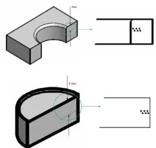
Specimens were obtained from the workpieces and slugs by a cutting through the holes. Cross-section images were revealed by optical microscope, showing the hardened layer size. The Vickers hardness profiles of this layer were determined in a MVK-G2 Mitutoyo tester, applying 4.9 N of test load. The indentations were made starting from the punch border penetration towards the sheet material, following the same methodology applied by Luo (1997). In this case measurements were taken up to 3 mm deep in the cut area in order to obtain the size of the work hardened zone generated from the punched workpieces. Besides, subsurface hardness slug profiles results will be also presented, and the measurements were made up to 4 mm deep from the slug surface. Fig. 2 presents a schematic representation of the hardness profiles measurements, for work pieces and slugs.
Figure 2. Schematic representation of hardness profiles measurements: (a) work piece, and (b) slug.
The subsurface hardness profiles were determined for different test cycles. In punching tests with coated tools these measurements were determined after the 1,000, 6,000, 12,000 and 22,000th holes, while for the tests using uncoated tools the cycles were measured after 1,000, 6,000 and 12,000th ones. For this uncoated tool the observed wear is high enough to interrupt the tests after the 12,000th hole. Thus, the tool life was about 80% larger in the presence of the PVD coating. Luo (1999) found similar results in punching tests with AISI 52100 as workpieces. The presented values of hardness are an average of all measurements regarding all test cycles, so that the maximum coefficient of variation was about 5%.
The tool life the criteria used were: - the minimum diameter of the punched hole should be smaller than 15.9 mm in more than 0.2 mm; - the deformation of the hole (difference between the largest and the smallest diameter) should be larger than 0.3 mm; - the variation of the hole’s final diameter or conic form should be larger than 0.3 mm. If none of the previous conditions were observed, when the noise level generated in the work area was too loud, for safety reasons the operation was suspended.
Results and Discussion
The variation of the Vickers hardness results from the border of the hole of the work pieces and their distribution is shown in Fig. 3, after punching with coated or uncoated tools.
Figure 3. Work piece hardness variation, after punching with coated or uncoated tools.
Figure 4. Cross-section of deformed work piece, after 1,000 cycles of punching.
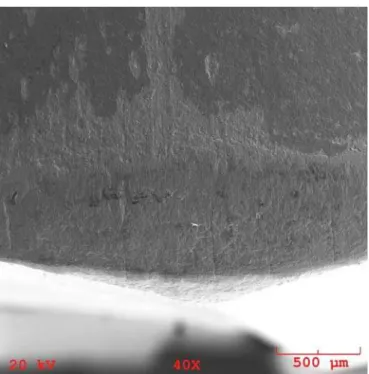
Figure 5 presents the subsurface hardness profiles obtained from the slugs after the punching tests. It shows that the work-hardened slugs presented a different profile from that observed for the work pieces. In this case, it was not observed a stabilization of hardness so that the original value was not reached up to 4 mm. Fig. 6 presents the cross-section image of the slug. Moreover, a higher value of maximum hardness close to the surface was measured. These results show that a larger amount of energy was consumed for slug plastic deformation than that for the work pieces. Again, the application of TiN coating in punch tools did not affect the slug or the work piece mechanical behavior with respect to the subsurface deformation.
The depth of this work-hardened layer will vary depending on the type of mechanical and thermal interaction, expressed by material properties, as can be seen in Eq. (1) (Sundararajan, 1987). Therefore, it is important to discuss the possible thermal balance that occurred during the punching process, based on the hardness differences found in the work pieces and slugs.
Figure 5. Slug hardness variation, after punching with coated or uncoated tools.
Figure 6. Cross-section of slug, after 1,000 cycles of punching.
The results obtained by Liu et al. (2002) help to understand the different mechanical behaviors of a tool, a chip or a slug. In their study, AISI 52100 steel was analyzed after hard turning, and this material was treated to obtain hardness between 30 and 70 HRC. The depth of hardened layer was determined as well as the chip hardness. For initial hardness of 50 HRC or larger, the chip could be tempered by the cutting heat, consequently its hardness falls. For same hardness conditions, the hardened layer kept constant about 0.1 mm. Thus, this observed behavior was verified for those situations where the heat generation is great, due to the large difficulty to cut the work piece.
For the results presented in Figs. 3 and 5, the initial hardness of low-carbon steel is much smaller than those studied by Liu et al. (2002). Therefore, the thermal effect is not significant, so that the hardened layer size of slug is larger than that observed for the work piece. On the other hand, the difference between their surface hardness was not remarkable. Moreover, the role of TiN coating at the interface should be also discussed.
J. of the Braz. Soc. of Mech. Sci. & Eng. Copyright © 2009 by ABCM January-March 2009, Vol. XXXI, No. 1 / 55
assertive agrees with that postulated by Hedenqvist et al. (1990), who affirmed that the thermal barrier effect during cutting process is not a main reason for the performance of coated tools. Following these authors, the reduction of cutting forces is the major contribution of larger wear resistance promoted by TiN coatings. Also, Sun et al. (1995) studied by finite element method the load bearing capacity of TiN coatings, and their results support the assertive made by by Hedenqvist et al. (1990). Here, it was found some evidences that support this point of view, as showed in Fig. 7.
Figure 7 shows the clearly difference between the surface roughnesses of slug due to the use of TiN coating. The punching operation performed with uncoated tool can lead to larger contact pressures at interface, which can promote a faster arising of work hardened material adhered to the side area of tool. These fragments have larger hardness than the original material, and consequently, could act as abrasives, as they become unattached. The abrasion mechanism was observed at tool surfaces, as presented in Fig. 8.
Figure 7. (a) Slug surface after 1,000 cycles punching with uncoated tool. (b) Slug surface after 1,000 cycles punching with coated tool. Both micrographs revealed in scanning electron microscopy.
Figure 8. Side wear revealed by scanning electron microscopy after 22,000th cycle in coated tool.
In this figure the presence of scratches is evident on the coated tool surface after its last life cycle. Thus, the side wear is a combination between adhesive and abrasive wear, a similar result was obtained by Luo (1997), for 12.5° shear angle of punch.
Another aspect of the microhardness profiles presented in Figs. 3 and 5 is a possible relationship between the microhardness profiles and residual stresses generated in the surfaces, which helps to support the hypothesis that the thermal effect contribution was less significant. When plastic deformation inhomogeneity is the only reason for the residual stress, the microhardness profile follows a pattern, similar to those obtained in this work, and verified in other processes, such as shoot peening (Martin et al., 1998). Thus, it is possible to conclude that plastic deformation due to punching tests had little influence of thermal effects.
With respect to the maximum hardness, this kind of measurement depends on the material properties, and also its metallurgical condition (Sundararajan, 1987). Richardson (1967) pointed out that the surface hardness measurement result of a material submitted to trepanning process is the best estimation of the maximum surface hardness of that material. Regarding this statement, Tab. 1 shows the maximum values of Vickers hardness observed in this study, and those determined by Richardson (1967) for 0.1% C cold-rolled steel after wear in the field containing stones and trepanning.
Table 1. Maximum Vickers hardness values for 0.1% C (MPa) obtained in the present study and by Richardson (1967) through two different processes.
Maximum value from work-hardened slug at 0.1 mm depth (Fig.3)
Worn in the field (Richardson, 1967)
Trepanned (Richardson, 1967)
Considering a slug maximum hardness determined in these tests, the difference between this value and that observed by Richardson is set within the usual experimental error accepted for hardness tests, so that these values can be considered similar. Other values obtained in abrasive system tests can also be considered. For instance, Pintaude et al. (2003) found a value of 3,700 MPa for AISI 1006 steel after pin-on-disk test with glass as abrasive material under 2.83 MPa of nominal stress.
On the other hand, when one compares the value (3,610 MPa) obtained during punching tests with the one obtained by Richardson after trepanning, one sees that his result is about 20% larger. However, Pintaude et al. (2003) pointed out that the technique used by Richardson (1967) was very much affected by surface roughness imposed by trepanning mechanism of cutting. When this effect could be avoided, the surface hardness value are similar to those obtained by trepanning so that it cannot be considered as the unique process to determine the maximum hardness when the cutting mechanism is predominant.
Moreover, the results presented here were determined at 0.1 mm from the punched hole, and the surface roughness after punching is not adequate to avoid its effect on the hardness measurement. Therefore, it is possible to conclude that the punching process raised a work-hardening level similar to the maximum hardness of that the material could reach.
Conclusions
After industrial punching tests in low-carbon steel, it is possible to conclude that the presence of TiN coating on the tool made of quenched and tempered AISI D2 steel did not affect the material subsurface deformation either the work pieces or the slugs. However, the tool life was improved about 80% using PVD TiN coatings. In this tests, side wear was the main kind of tool wear, which was a combination between adhesion and abrasion mechanisms.
The size of the hardened layer was larger in the slugs than that observed on the work pieces, showing that the high amount of energy is employed to deform this part. Considering the work piece hardened layer, the observed result agreed with the ones found by Luo (1997).
On the maximum hardness at surface, the measured values were similar to those determined by Richardson (1967) for 0.1%C steel under wear in the field containing stones. Besides this result, some considerations were made in respect to the concept of the maximum hardness, and it is possible to conclude that the punching process promoted an increase in subsurface hardness equivalent to the limit that the low-carbon steel could be reached.
The microhardness profiles of the work pieces and slugs could help to understand that the plastic deformation due to the punching process was too little affected by thermal effects.
Acknowledgements
Authors acknowledge Dana Indústrias Ltda for the license to use punching machines, and to Brasimet Indústria e Comércio S.A for the production and characterization of TiN coatings.
References
Hedenqvist, P., Olsson, M., Wallén, P., Kassman, Å., Hogmark, S., Jacobson, S., 1990, “How TiN coatings improve the performance of high speed steel cutting tools”, Surface and Coatings Technology, Vol.41, pp. 243-256.
Leskovšek, V., Podgornik, B., Nolan, D., 2008, “Modelling of residual stress profiles in plasma nitrided tool steel”, Materials
Characterization, Vol.59, pp. 454-461.
Liu, X.L., Wen, D.H., Li, Z.J., Xiao, L., Fan, F.G., 2002, “Experimental study on hard turning hardened GCr15 steel with PCBN tool”, J. Mater.
Process. Technol., Vol.129, pp. 217-221.
Loh, N.H., Tam, S.C., Miyazawa, S., 1989, “Statistical analyses of the effects of ball burnishing parameters on surface hardness”, Wear, Vol.129, pp. 235-243.
Luo, S.Y., 1997, “Studies on the wear conditions and the sheared edges in punching”, Wear, Vol.208, pp. 81-90.
Luo, S.Y., 1999, “Effect of the geometry and the surface treatment of punching tools on the tool life and wear conditions in the piercing of thick steel plate”, J. Mater. Process. Technol., Vol.88, pp. 122-133.
Mamalis, A.G., Vosniakos, G. C., Vacevanidis, N. M., 1988, “Residual Stress Distribution and Structural Phenomena of High-Strength Steel Surfaces Due to EDM and Ball-Drop Forming”, Annals of the CIRP, Vol.37, pp. 531-535.
Martin, U., Altenberger, I., Scholtes, B., Kremmer, K., Oettel, H., 1998, “Cyclic deformation and near surface microstructures of normalized shot peened steel SAE 1045”, Materials Science and Engineering A, Vol.246, pp. 69–80.
Morimoto, T., 1988, “Work hardening and tool surface damage in burnishing, Wear, Vol.127, pp. 149-159.
Pintaude, G., Tanaka, D.K., Sinatora, A., 2003, “The effects of abrasive particle size on the sliding friction coefficient of steel using a spiral pin-on-disk apparatus”, Wear, Vol.255, pp. 55-59.
Richardson, R.C.D., 1967, “The maximum hardness of strained surfaces and the abrasive wear of metals and alloys”, Wear, Vol.10, pp. 353-382.
Roessig, K.M., Mason, J.J., 1999, “Adiabatic shear localization in the dynamic punch test, part I: experimental investigation”, Int. J. Plasticity, Vol.15, pp. 241-262.
Sun, Y., Bloyce, A., Bell , T., 1995, “Finite element analysis of plastic deformation of various TiN coating/ substrate systems under normal contact with a rigid sphere”, Thin Solid Films, Vol.271, pp. 122-131.
Sundararajan, G., 1987, “A new model for two-body abrasive wear on the localization of plastic deformation”, Wear, Vol.117, pp. 1-35.