Comparative Study of SSVEP- and
P300-Based Models for the Telepresence Control of
Humanoid Robots
Jing Zhao1☯, Wei Li1,2,3☯
*, Mengfan Li1
1School of Electrical Engineering and Automation, Tianjin University, Tianjin, China,2Department of Computer & Electrical Engineering and Computer Science, California State University, Bakersfield, California, United States of America,3Robotics State Key Laborotory, Shenyang Institute of Automation, Chinese Academy of Sciences, Shenyang, China
☯These authors contributed equally to this work. *[email protected]
Abstract
In this paper, we evaluate the control performance of SSVEP (steady-state visual evoked potential)- and P300-based models using Cerebot—a mind-controlled humanoid robot plat-form. Seven subjects with diverse experience participated in experiments concerning the open-loop and closed-loop control of a humanoid robot via brain signals. The visual stimuli of both the SSVEP- and P300- based models were implemented on a LCD computer moni-tor with a refresh frequency of 60 Hz. Considering the operation safety, we set the classifica-tion accuracy of a model over 90.0% as the most important mandatory for the telepresence control of the humanoid robot. The open-loop experiments demonstrated that the SSVEP model with at most four stimulus targets achieved the average accurate rate about 90%, whereas the P300 model with the six or more stimulus targets under five repetitions per trial was able to achieve the accurate rates over 90.0%. Therefore, the four SSVEP stimuli were used to control four types of robot behavior; while the six P300 stimuli were chosen to con-trol six types of robot behavior. Both of the 4-class SSVEP and 6-class P300 models achieved the average success rates of 90.3% and 91.3%, the average response times of 3.65 s and 6.6 s, and the average information transfer rates (ITR) of 24.7 bits/min 18.8 bits/ min, respectively. The closed-loop experiments addressed the telepresence control of the robot; the objective was to cause the robot to walk along a white lane marked in an office environment using live video feedback. Comparative studies reveal that the SSVEP model yielded faster response to the subject’s mental activity with less reliance on channel selec-tion, whereas the P300 model was found to be suitable for more classifiable targets and required less training. To conclude, we discuss the existing SSVEP and P300 models for the control of humanoid robots, including the models proposed in this paper.
OPEN ACCESS
Citation:Zhao J, Li W, Li M (2015) Comparative Study of SSVEP- and P300-Based Models for the Telepresence Control of Humanoid Robots. PLoS ONE 10(11): e0142168. doi:10.1371/journal. pone.0142168
Editor:Mikhail A. Lebedev, Duke University, UNITED STATES
Received:February 26, 2015
Accepted:September 11, 2015
Published:November 12, 2015
Copyright:© 2015 Zhao et al. This is an open access article distributed under the terms of the
Creative Commons Attribution License, which permits unrestricted use, distribution, and reproduction in any medium, provided the original author and source are credited.
Data Availability Statement:All data files available from:https://zenodo.org/record/32883.
Funding:This work was supported in part by The National Natural Science Foundation of China (No. 61473207) and the Ph.D. Programs Foundation of the Ministry of Education of China (No.
20120032110068). The funder had no role in study design, data collection and analysis, decision to publish, or preparation of the manuscript.
use live video feedback to telepresence control the humanoid robot in many applications, e.g., the exploration and surveillance in an unknown environment [7].
Methods of acquiring brain signals are classified as either invasive or non-invasive. Non-invasive techniques include magnetoencephalography (MEG), electroencephalograph (EEG), and functional magnetic resonance imaging (fMRI). The most commonly used non-invasive method is the acquisition of EEG signals from electrodes placed on the scalp. This method is inexpensive, easy to use, and provides acceptable temporal resolution. The types of electrical potentials that can be acquired through EEG for the development of control models include motor imagery (MI) potentials, the steady-state visual evoked potentials (SSVEPs), and the P300 potentials. MI potentials, also known as mu/beta rhythms, are induced by the motor cor-tex through the spontaneous imagining of body movements. Ramos-Murguialday et al. trained a patient to modulate motor imagery potentials to control a neuroprostheses [8]. Typically, an MI-based model delivers limited classifiable states and relatively low classification accuracy; therefore, such a model alone is not commonly used to control a humanoid robot with full body movements; in fact, the sole study in which motor imagery potentials have been used to control the walking gait of a simulated humanoid robot was reported in [9]. To control multi-ple behaviors of a humanoid robot, Choi et al. combined an MI-based model with SSVEP- and P300-based models [10]. The SSVEP is the potential that naturally responds to visual stimuli at specific frequencies. Tidoni et al. presented an SSVEP-based model for directing a humanoid robot in performing a pick-and-place task [11]. The P300 potential is an event-related potential (ERP) with a positive deflection that is time-locked to auditory or visual stimuli. Bell et al. described a P300-potential-based method for the selection of a target toward which to direct a humanoid robot [12]. However, there is a lack of detailed comparative evaluations of both SSVEP and P300 models.
time response; for example, increasing the repetition number from 5 to 8 caused the average success rate to increase to 98.8% but increased the average response time to 10.56 s and decreased the average ITR to 14.1 bits/min.
This paper is organized as follows: the section Cerebot Platform presents the system archi-tecture of the mind-controlled humanoid robot platform, the section SSVEP and P300 Models discusses the implementation of the SSVEP and P300 models, the section Evaluation Studies describes the evaluation procedures for the SSVEP and P300 models, and the section Experi-mental Results discusses the evaluation results and compares the performance of both models for the telepresence control of a humanoid robot in a task in which the objective was to cause the robot to follow a white lane marked in an office environment using live video feedback.
Cerebot Platform
We used Cerebot—a mind-controlled humanoid robot platform that consists of a Cerebus™
Data Acquisition System and a NAO humanoid robot—to evaluate the SSVEP and P300 mod-els. The Cerebus™Data Acquisition System is capable of recording, pre-processing and display-ing bio-potential signals acquired by various types of electrodes. It provides multiple analog I/ O signals and digital I/O signals and is capable of recording up to 128 signal channels simulta-neously at a sampling rate of 30 kHz with 16-bit resolution. Its software development kits in C ++ and MATLAB provide users with the ability to easily design experimental procedures. In this study, a NAO humanoid robot with 25 degrees of freedom was used to evaluate the SSVEP and P300 models. The NAO robot was equipped with multiple sensors, including 2 cameras, 4 microphones, 2 sonar rangefinders, 2 IR emitters and receivers, 1 inertial board, 9 tactile sen-sors, and 8 pressure sensors. Both Choregraphe and C++ SDK environments were available for the creation and editing of movements and interactive robot behavior.
Fig 1depicts the software architecture of Cerebot for the implementation of control strate-gies via brainwaves in the OpenViBE environment [13–15]. A number of software programs are integrated into Cerebot, such as OpenGL, OpenCV, MATLAB, Webots, Choregraphe, Cen-tral software, and user-developed programs written in C++ and MATLAB [15]. Cerebot acquires brain signals through Cerebus™, extracts their features, classifies them based on their patterns, and sends corresponding commands to control the behavior of the humanoid robot via a wireless connection.
SSVEP and P300 Models
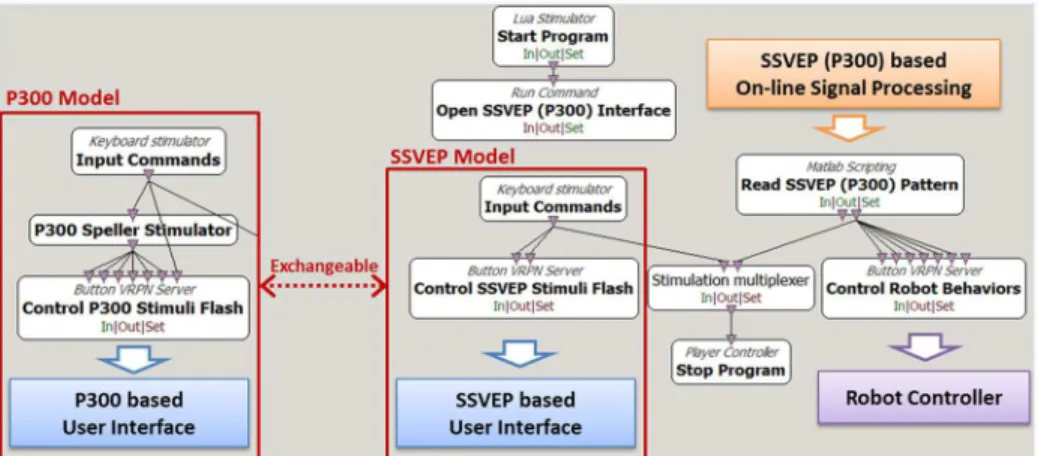
Fig 2presents the flow diagram for the implementation of the SSVEP and P300 models on
Cer-ebot in the OpenViBE environment. These models consist of modules for the activation of the
Fig 1. The OpenViBE-based Cerebot structure.Cerebot acquires brain signals via Cerebus™, flashes visual stimulus images, and displays live video of the robot’s state and surroundings.
SSVEP or P300 visual stimulus interface, the on-line processing of the acquired brainwaves, and the control of the behavior of the humanoid robot.
SSVEP Model
In 1966, Regan discovered the harmonics of electrical potentials evoked by the flickering of a sinusoidally modulated light using an analog Fourier series analyzer [16]. These types of brain-waves respond to the modulation of visual stimuli at a given frequency and are known as SSVEPs. SSVEPs prominently appear throughout the visual cortex in the occipital region in channels O1, O2 and Oz of the scalp [17], as shown inFig 3(a). The brain signalyi(t) evoked by theithSSVEP stimulus at timetis described by [18]
yiðtÞ ¼
X
Nh
k¼1
ai;ksinð2pkfitþFi;kÞ þBi;t i¼1;2;. . .;N ð1Þ Fig 2. SSVEP and P300 models implemented independently in the OpenViBE programming
environment.Execution of the SSVEP or P300 model requires only the switching of the corresponding modules. The modules enclosed in the white boxes are the functions provided by the OpenViBE package, and the arrows indicate data flow paths.
doi:10.1371/journal.pone.0142168.g002
Fig 3. Electrode placement and SSVEP signal spectrum.(a) EEG electrodes placed in accordance with the International 10–20 system. The electrode circled with a blue solid line is the channel in which brainwaves are induced by the SSVEP model, and the electrodes circled with a red dashed line are the prominent channels among which the most responsive channel is selected to acquire the brainwaves induced by the P300 model. (b) SSVEP power spectrum of subject subj1 acquired from channel Oz when the subject was staring at flickering targets modulated at four frequencies.
Wherefiis theflickering frequency of theithvisual stimulus,Nis the total number of stimuli,
Nhis the number of considered harmonics,ai,kandFi,kare the amplitude and phase of each sinusoid, andBi,tincludes noise, artifacts and any components that are irrelevant to the SSVEP response. The SSVEP model implemented on Cerebot consists of two essential modules. The first one is the User Interface forflickering visual stimuli at precise frequenciesfi, which elicits
brain signals that can be expressed as a number of sinusoidsX Nh
k¼1
ai;ksinð2pkfitþFi;kÞ. In this
study, the User Interfaceflickered four images that served as the visual stimuli at 5.45 Hz, 6.67 Hz, 8 Hz, and 10 Hz on a computer monitor [19]. In order to telepresence control the human-oid robot safely, we investigated visual stimuli with the accurate rate over 90%. Considering the availableflashing frequencies of the LCD monitor [20] and the influence among harmonic components of SSVEPs [21], we scanned all the possibleflashing frequencies from 0 to 60 Hz and tested the classification accuracies of the SSVEP models from 3 to 6 visual stimuli.Table 1 shows that the classification accuracies decreased as the stimuli increased. The 6-class SSVEP model only reached an average accuracy of 83.1%, so the 4-class SSVEP model met the manda-tory for control of the four robot walking behaviors: walking forward, walking backward, and turning left and right. The work [22] used the 6-class SSVEP model to control a humanoid robot with a response time of 7.52 s, but it did not explain how to obtain the accuracy and ITR. We could not repeat the tests due to omitting the detailed experimental procedures and the test conditions, but our single channel-based algorithm reached the compatible classification accu-racy to the one achieved by the algorithms [23] used for the tests in [22], as listed inTable 1. The second module is the On-line Signal Processing module for the removal ofBi,tand the extraction of the features ofai;niði¼
1; 2; 3;4Þ, which represent the four stimulus targets, under the constraintai;ni>si, wherenirepresents the most responsive harmonic frequency
for theithtarget andσiis the threshold.niandσimust be calibrated for each subject during an off-line training process becauseai;nistrongly depends on the individual and exhibits
consider-able inherent variability.ni. is determined based on the power spectrum features of the subject.
σiis calibrated by thoroughly considering the response time and classification accuracy to ensure the following behavior:
s i ¼
ai;ni; when subject is staring at thei
thtarget
>ai;ni; when subject is at rest or staring at other targets
ð2Þ
(
Therefore, an experienced researcher will train each subject to shift his/her focal point on an image and to adjust his/her mental state.Fig 3(b)provides an example of the power spectrum features of SSVEP signals.
The modules enclosed in the white boxes inFig 2are the functions provided by the Open-ViBE package, and the arrows indicate the data flow paths. To execute the SSVEP model, the Start Program and Open SSVEP Interface toolboxes initiate the User Interface, which is pro-grammed in C++ and depicted inFig 4, and the Read SSVEP Pattern toolbox initiates the On-line Signal Processing module via the MATLAB engine. The Input Commands toolbox delivers Table 1. Classification accuracy of the SSVEP models from 3 to 6 stimuli.
Model Classification accuracy (%)
3-class 4-class 5-class 6-class
SSVEP 91.9 90.3 88.4 83.1
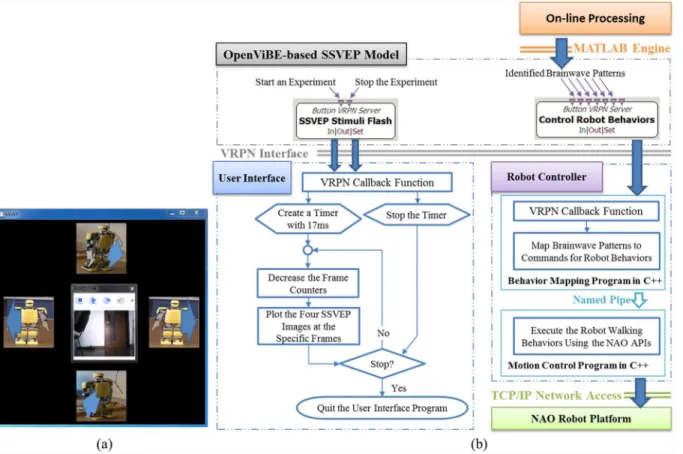
commands to the Control SSVEP Stimuli Flash toolbox and the Stop Program toolbox to start or end the experimental procedure. The Control SSVEP Stimuli Flash toolbox activates the User Interface, which was displayed in the middle of a 22-inch LCD monitor in this study, as shown inFig 4(a), to display live video from the camera embedded in the NAO robot via a TCP/IP network. The User Interface simultaneously flashes four robot images on the monitor to serve as visual stimuli; in this study, the monitor had a resolution of 1440×900 pixels and a refresh rate of 60 frames per second. The four images represent four robot behaviors: walking forward, turning right, turning left, and walking backward. Our previous works used several types of humanoid robot images as visual stimuli. In this study, the robot images are used as the visual stimuli to intuitively represent the robot behaviors to be controlled, instead of which type of humanoid robot to be controlled, so the KT-X PC robot images provide very compre-hensive information to encode the walking behaviors regardless of robot types, e.g., the KT-X PC robot or the NAO robot.Fig 4(b)shows the flow diagram of the User Interface. The Read SSVEP Pattern toolbox invokes the On-line Signal Processing module, written in MATLAB, which is the key module for the management of an experiment; its functions include reading brain signals from the Cerebus™EEG system and translating them into control commands depending on the received brainwave patterns. The Robot Controller receives the control com-mands from the Control Robot Behaviors toolbox to activate the corresponding robot behav-iors. The Robot Controller incorporates Choregraphe, Webots, and two user-developed programs written in C++, as shown inFig 4(b). The Robot Controller is able to control either Fig 4. User Interface and its flow diagrams for the SSVEP model.(a) The User Interface for the SSVEP model displays live video in the middle window and flickers four images at four different frequencies on the periphery that represent different humanoid robot behaviors. (b) The flow diagrams describe the User Interface and the Robot Controller for the SSVEP model for an on-line control experiment.
the real NAO robot or a virtual robot via the TCP/IP network. Choregraphe is used to create the NAO robot behaviors, and Webots is used to verify these behaviors through the control of a virtual NAO robot. To end the experiment, the Control SSVEP Stimuli Flash
toolbox deactivates the User Interface, and the Read SSVEP Pattern toolbox terminates data collection.
The SSVEP model acquires brain signals at a sampling rate of 1 kHz from channel Oz in the occipital region, filters them using a band-pass filter between 3 and 30 Hz, uses a window of 3 sec in width to segment them, and applies a Fast Fourier Transform (FFT) every 1 sec to calcu-late their power spectrum A(t):
AðtÞ ¼jFFTðyððt 3Þ Sþ1 :tSÞÞj ð3Þ
WhereSis the sampling rate,y(t×S) is the datum sampled attsec, and y((t−3) ×S+ 1:t×S) is a brainwave segment in the window. The most responsive power spectrum at thenithharmonic frequency for theithSSVEP stimulus target is approximately equal toai;niðtÞinEq 1and is
nor-malized as follows:
pi;niðtÞ ¼
ai;niðtÞ X30
f¼3AðtÞ=Nf
ði¼1;2;3;4Þ ð4Þ
whereX30
f¼3AðtÞ=Nf denotes the average amplitude of the spectrum between 3 and 30 Hz. The normalized amplitudespi;niof the four frequencies that are used to establish the feature
vector are detected when it is above the thresholdσi.
P300 Model
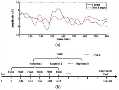
In 1965, Sutton et al. discovered an electrical potential that exhibited a positive fluctuation within approximately 300 ms after the presentation of an unexpected event (visual, auditory, etc.) [24]. Smith et al. named this potential the‘P300’potential based on its polarity and rela-tively fixed latency [25]. A P300 potential is induced prominently in channels Pz, Fz, and Cz in the midline centroparietal regions, and its latency varies from 300 ms to 800 ms when a set of visual stimuli are presented unexpectedly in a random sequence [26], as shown inFig 5(a). The feature vector Fiof this potential for theithtarget is extracted by capturing the data between 100 and 500 ms and downsampling them.
Fi¼downsample
XNr
j¼1yi;jð
0:1t0:5Þ
Nr
0
@
1
A i¼1;2;. . .;N ð5Þ
Whereyi,j(t) is the sampled datum acquired after the presentation of theithP300 target in
complexity [27,28]. We were able to down-sample the brain signals from 1000 Hz to 20 Hz [29] according to Shannon’s theorem.
Execution of the P300 model in the OpenViBE environment requires only the replacement of the“SSVEP Model”with the“P300 Model”and the switching of the modules Open SSEVP (P300) Interface, Read SSVEP (P300) Pattern, and SSVEP (P300) On-line Signal Processing from the SSVEP model to the P300 model, as shown inFig 2. The other toolboxes, including Robot Controller, remain unchanged. The P300 model uses the P300 Speller Stimulator pro-vided by the OpenViBE package to load six robot images to serve as visual stimuli and to define their flashing timeline, as shown inFig 5. The P300 Stimuli Flash toolbox sends the visual sti-muli to the P300 User Interface via the VRPN protocol.Fig 6(a)presents the flow diagram for the P300 User Interface, with six robot images representing six robot walking behaviors: walk-ing forward, walkwalk-ing backward, shiftwalk-ing left, shiftwalk-ing right, turnwalk-ing left, and turnwalk-ing right, as shown inFig 6(b). During a P300 experiment, one repetition consists of flashing each of the six robot images one by one in a random order.Fig 6(c)presents an example in which the shift-ing-left image is presented while the others are shielded by a black square with a white solid cir-cle. The 1.32 s repetition duration includes all six instances of the presentation of a visual stimulus separated by a 220 ms inter-stimulus interval (ISI), as shown inFig 5(b).
For the acquisition of P300 potentials with recognizable features, the subject focuses on his/ her target stimulus throughout some number of repetitions, constituting a trial. The repetition number of a trial strongly affects the performance of the P300 model. To ensure an objective comparison of the P300 and SSVEP models, we chose to perform the experiments using 5 repe-titions per trial. The P300 On-line Signal Processing module processes the acquired brain sig-nals as follows [29,30]. First, the module filters the brain signals using a digital filter with a pass-band of 0.5–26 Hz and divides them into epochs of 500 ms. Second, the module removes the signal drift by subtracting the mean signal value from each epoch and downsamples the sig-nals from 1000 Hz to 20 Hz. Next, the module averages the downsampled sigsig-nals over all 5 rep-etitions and uses the FLDA classifier to identify the stimulus target, i.e., the subject’s intention, Fig 5. P300 ERPs and our flashing timeline for the P300 model.(a) A P300 potential, which exhibits a large positive deflection at approximately 300 ms, as represented by the blue curve, is recorded in channel Pz when a subject is staring at a flashing target image. (b) Throughout the flashing timeline, the P300 Speller Stimulator toolbox presents the six visual stimuli one by one in a random order.
based on the feature vectors. Finally, the module sends control commands to the Robot Con-troller to activate the corresponding robot behavior.
Evaluation Studies
Subjects
The experiments were performed in an office environment without electromagnetic shielding. The seven subjects (six male and one female, aged 22–29) participated in both the SSVEP and P300 experiments. Among them, subj7, who was the only female subject, was proficient in the P300 experiments but had no prior experience related to the SSVEP experiments; subj1 and subj3 had participated in a number of SSVEP experiments but never in P300 experiments; subj2 had participated in both types of experiments several times; and subj4, subj5, and subj6 had no prior experience related to any of the experiments. All subjects had normal or cor-rected-to-normal vision and understood the experimental procedures very well. Each subject was seated in a comfortable armchair, 70 cm away from the visual stimuli presented on a 22-inch LCD monitor with a 60 Hz refresh rate. Brain signals were acquired at a sampling rate of 1 kHz using a standard EEG cap with 30 channels, as shown inFig 3. The ground electrode was placed at FPz on the forehead, and a linked-mastoids reference was used. This project was reviewed and approved by Tianjin medical university general hospital ethics committee, and Fig 6. User Interface and its flow diagrams for the P300 model.(a) The flow diagram of the User Interface for the P300 model and its communication with the other modules. (b) The User Interface presents six robot images, each corresponding to different walking behaviors. (c) The User Interface flashes the images one by one in a random order.
with no prior experience used the off-line process to become familiar with the experimental procedure.
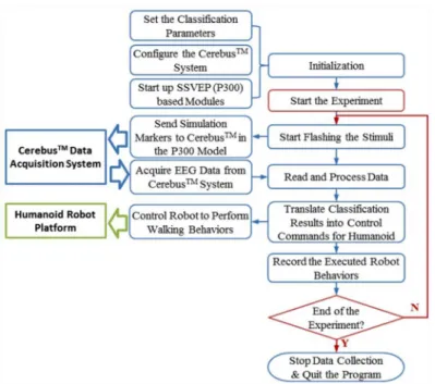
In the on-line testing process, the subjects were requested to control a random sequence of robot walking behaviors through staring at the corresponding visual stimuli. Each subject con-ducted the experiments using the SSVEP and P300 models respectively to evaluate their perfor-mance for the open-loop control of humanoid walking behaviors.Fig 7presents the flow chart that describes the on-line testing procedure. After the experiment was initiated, the SSVEP or P300 User Interface began flashing the visual stimuli. The P300 User Interface also generated a stimulation marker to indicate when the corresponding visual stimulus was triggered. The On-line Signal Processing module read the brain signals received from Cerebus™, processed them, and sent the identified control command to the Robot Controller. We used success rate, response time, and information transfer rate (ITR) to evaluate the performance of the SSVEP and P300 models. The success rate represents the percentage of robot behaviors that were suc-cessfully activated. The response time,T, represents the time elapsed after the subject received an instruction that the model required to successfully activate the robot behavior. The ITR in units of bits/min is defined in [31].
ITR¼plog2ðpÞ þ ð1 pÞlog2 1 p N 1
þlog2ðNÞ
T ð6Þ
whereNis the number of defined robot behaviors,Tis the response time, andpis the success rate.
In the comparative experiments of the closed-loop control of the NAO humanoid robot, the objective was to direct the robot to follow a white lane mark with live video feedback using the SSVEP and P300 models respectively, as shown inFig 8. To objectively evaluate the closed-loop control performance, the subject who achieved the best performance using both the SSVEP and P300 models in the open-loop control evaluations was selected to perform these experiments for 3 repetitions. The subject tried to utilize four robot behaviors defined for the SSVEP model and six robot behaviors defined for the P300 model to control the robot to walk on the path. We used the total execution time and the number of activated behaviors averaged over 3 repetitions of the experiments to evaluate the performance achieved in the closed-loop control.
Experimental Results
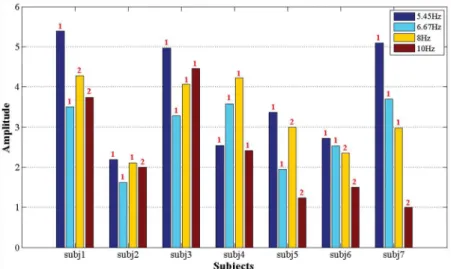
the inherent differences in their sensitivities to these frequencies.Fig 9shows the average fea-ture amplitudepi;niat theni
thharmonic frequency that was the most responsive for theith SSVEP stimulus target, as calculated usingEq 4.
The following remarks can be made regarding the results. 1. subj1, who understood the SSVEP experiments very well, achieved the highest average success rate of 100%, the shortest average response time of 2.69 s, and the best average ITR of 44.6 bits/min. 2. subj2 achieved a success rate of only 82.6%, even after considerable training, whereas subj4, subj6 and subj7, who were the first-time participants in SSVEP experiments, achieved average success rates of over 90%. These results indicate that subj2’s brain activity is insensitive to the presented SSVEP visual stimuli. 3. The three subjects who were experienced with SSVEP and P300 ERP experiments, subj1, subj2, and subj3, responded to the visual stimuli presented in both experi-ments much more rapidly than did the subjects who had no prior experience. Interestingly, Fig 7. Procedure for the evaluation of the performance of the SSVEP and P300 models in the open-loop experiments for the control of humanoid robot behaviors.
doi:10.1371/journal.pone.0142168.g007
Fig 8. Comparative study of the telepresence control of the humanoid robot with the objective of following a white lane mark in an office environment with live video feedback.
subj7, who was proficient in P300 experiments, achieved response times comparable to those of the experienced subjects in her first experience with an SSVEP experiment. It is possible that a subject who is proficient in the visual stimuli of one experiment may be able to quickly adapt to the visual stimuli of the other experiment. 4. subj5, who was a first-time participant in SSVEP experiments, underwent a total of 72 trials in two days. On the first day, subj5 became fatigued and his concentration diminished rapidly; therefore, he achieved a success rate of only 72.5% in 40 trials. However, on the second day, his success rate increased to 84.4% in 32 trials.
Table 3lists the evaluation results obtained in the experiments for the control of six robot walking behaviors using the P300 model: walking forward, walking backward, shifting left, shifting right, turning left, and turning right. Unlike in the SSVEP experiments, in the P300 Mean±SD 88.6±14.2 91.5±13.6 90.7±13.3 88.5±10.5 90.3±7.7 3.65±0.67 24.7±10.2 NNew participant in SSVEP experiments.
FFemale subject.
doi:10.1371/journal.pone.0142168.t002
Fig 9. Feature amplitudes at the most responsive harmonic frequency for the seven subjects.These features were induced by the four SSVEP targets flickering at 5.45 Hz, 6.67 Hz, 8 Hz, and 10 Hz. The red numbers above the columns indicate the most responsive harmonic frequencies for each stimulus target and each individual.
experiments, brain signals were acquired from five channels, Oz, Pz, CPz, Cz, and FCz, which exhibit considerable differences in their P300 responses to visual stimuli from individual to individual. Therefore, we selected the most responsive channel for each subject, as listed in Table 3, for use in controlling the walking behavior of the robot. All seven subjects, including those with no prior experience, achieved success rates of over 95% using the selected channels. The time required for the classification of a P300 potential is calculated as follows:
t¼tISINNr ð7Þ
WheretISIis the inter-stimulus interval of 0.22 s,N= 6 is the number of P300 stimulus tar-gets, andNris the number of repetitions per trial.Fig 10presents the average accuracy for each subject vs. the number of repetitions. ForNr= 8, all subjects, including those with no prior experience, achieved success rates of over 95%. Under these conditions, the P300 model requires a response time of 10.56 s to generate a control command. We used a repetition num-ber at which all seven subjects achieved comparable performance using the SSVEP model. We selected 5 repetitions per trial for evaluation because the P300 model with 5 repetitions achieved an average success rate of 91.3%, an average response time of 6.6 s, and an average ITR of 18.8 bits/min for all seven subjects.
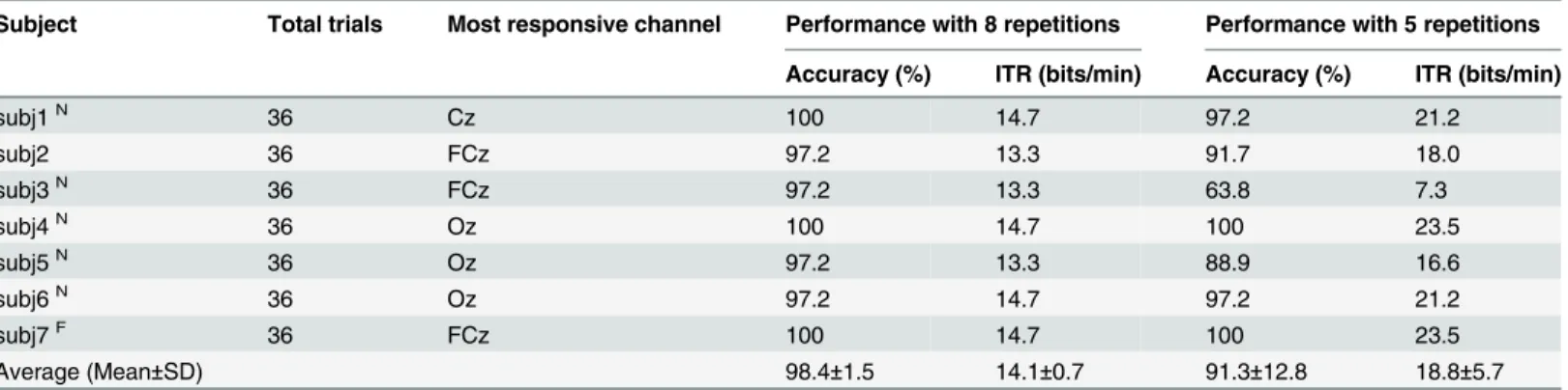
Table 3. Evaluation results for the control of six robot behaviors using the P300 model with 8 or 5 repetitions per trial.
Subject Total trials Most responsive channel Performance with 8 repetitions Performance with 5 repetitions
Accuracy (%) ITR (bits/min) Accuracy (%) ITR (bits/min)
subj1N 36 Cz 100 14.7 97.2 21.2
subj2 36 FCz 97.2 13.3 91.7 18.0
subj3N 36 FCz 97.2 13.3 63.8 7.3
subj4N 36 Oz 100 14.7 100 23.5
subj5N 36 Oz 97.2 13.3 88.9 16.6
subj6N 36 Oz 97.2 14.7 97.2 21.2
subj7F 36 FCz 100 14.7 100 23.5
Average (Mean±SD) 98.4±1.5 14.1±0.7 91.3±12.8 18.8±5.7
NNew participant in P300 experiments. FFemale subject.
doi:10.1371/journal.pone.0142168.t003
Fig 10. Average accuracy for each subject with different number of repetitions.
averaged over three repetitions of the experiments. The average execution times were 96 s and 118 s and the average numbers of output commands were 18.7 and 13.7 for the SSVEP and P300 models, respectively. The P300 model outputs fewer control commands than does the SSVEP model; however, the P300 model requires a longer execution time than does the SSVEP model because the average response time of 8.6 s that is required by the P300 model to output a command is longer than the 5.4 s required by the SSVEP model. Note that for both the SSVEP and P300 models, the average response times for closed-loop control were found to be longer than those for open-loop control. This is because for the closed-loop control experiment, the subject required an additional 2 seconds to output the chosen robot behavior by means of his mental activity based on live video feedback. This additional time of 2 s allowed the subject to make a decision regarding the selection of a suitable robot behavior. The experimental results also show that the P300 model requires the activation of fewer robot behaviors to accomplish the line-following task than does the SSVEP model because the shifting-right and shifting-left behaviors provided by the P300 visual stimuli allow the subject greater flexibility in the control of the walking pattern of the humanoid robot.Table 4shows that subj1 used 3 TL (turning left) and 4 TR (turning right) behaviors on average to adjust the walking direction of the robot at the two 90-degree corners on the white path when using the SSVEP model, whereas subj1 used 0.7 TL, 1.3 TR and 3 SR (shifting right) behaviors on average when using the P300 model.
Conclusions and Future Work
Reducing the total number of electrodes may benefit to develop practical BRI devices [32]. In view of controlling the humanoid robot via brain signals, it is essential to develop the algo-rithms that are easily implemented and run in real-time, so our study aims at comparing both the P300 and SSVEP models using the least number of electrodes, i.e., a signal electrode, a ref-erence electrode, and a ground electrode. Our on-line testing results for 7 subjects show that the SSVEP model achieved an average success rate of 90.3%, and the P300 model with 5 repeti-tions achieved an average success rate of 91.3%. These accuracy rates meet the requirements on the on-line control of the humanoid robot with live video feedback. Currently, there may be no general superiority of any approach over the others in BCI classification as indicated in [33]. Our SSVEP-based model achieving the compatible performance to the one yielded by the P300-based model used a single channel to telepresence control the NAO robot. The single channel may not be a perfect choice for some BCI systems as the channel layout has to be indi-vidualized and the classification accuracies are lower than those using multi-channel tech-niques [34,35]. However, our research activity aims at the comparative study of the SSVEP and P300 models for the telepresence control of the humanoid robot, which requires the ease of implementation and operates in real-time. For example, the single channel is suitable for our on-going project on education-oriented brain-controlled robot system equipped with a very low-cost EEG device developed by our team because multiple electrodes are not available.
In our study, each subject has to conduct three sessions of experiments. In the first session, the subject conducted an off-line calibration process, which recorded the brain signals for training the classifier. In this case, the subject collected the brain signals of staring at visual sti-muli of the P300 and SSVEP models without the need for steering a robot. In the second ses-sion, the subject on-line controlled the simulated or physical NAO robot in open loop to randomly activate a sequence of robot behaviors for testing the control success rates. Usually, steering the simulated NAO robot is good for game design projects [36] as the physical robot is unavailable or for the initial practice to get familiar with the brain-controlled NAO robot sys-tem in avoiding to damage the real robot. In this study, the subject steered the physical human-oid robot to verify the success rates achieved in the off-line training process. In the third session, that the subject telepresence controlled the physical humanoid robot to perform the line-following task based on live videos was the target of this study.Table 5summarizes the existing work on the closed-loop control of humanoid robots using the human mind to present a performance comparison based on three criteria (although one or two criteria are lacking for some approaches): success rate, response time, and ITR. Works [9,10,13,22,37,38] report the control of a robot using motor imagery models, which deliver low success rates. Works [9,39,40] report experiments involving the control of a virtual robot; by comparison, control-ling a real robot would be much more challenging. Overall, both the SSVEP and P300 models proposed in this paper achieved superior performances compared with those previously reported, as shown inTable 5.
Acknowledgments
The authors would like to express their gratitude to Mr. Gouxing Zhao, Mr. Hong Hu, and Mr. Qi Li for their assistance in performing the experiments reported in this paper. The authors also appreciate the suggestions of the reviewers which have greatly improved the paper.
Author Contributions
Conceived and designed the experiments: JZ WL ML. Performed the experiments: JZ ML. Ana-lyzed the data: JZ WL. Contributed reagents/materials/analysis tools: WL. Wrote the paper: JZ WL.
References
1. McFarland DJ, Wolpaw JR. Brain-computer interface operation of robotic and prosthetic devices. Com-puter. 2008; 41(10): 52–56.
2. Lebedev MA, Nicolelis MA. Brain-machine interfaces: past, present and future. Trends Neurosci. 2006; 29(9): 536–546. PMID:16859758
3. Ortiz-Rosario A, Adeli H. Brain-computer interface technologies: from signal to action. Rev Neurosci. 2013; 24(5): 537–552. doi:10.1515/revneuro-2013-0032PMID:24077619
4. Hirai K, Hirose M, Haikawa Y, Takenaka T. The development of Honda humanoid robot. Proceedings of the 1998 IEEE International Conference on Robotics and Automation; 1998 May 16–20; Leuven, Bel-gium. IEEE; 1998. p. 1321–1326.
5. Kaufmann T, Herweg A, Kubler A. Toward brain-computer interface based wheelchair control utilizing tactually-evoked event-related potentials. J Neuroeng Rehabil. 2014; 11(1): 7.
6. Chai RF, Ling SH, Hunter GP, Tran Y, Nguyen HT. Brain-computer interface classifier for wheelchair commands using neural network with fuzzy particle swarm optimization. IEEE J Biomed Health. 2014; 18(5): 1614–1624.
Finke et al., 2013[38] P300 and2-class MI Real Tasks related to assistance and telepresence
P300: 80 MI: 78 N/A N/A
Gergondet et al., 2011 [42], 2012[43]
4-class SSVEP Real Navigation and object selection
N/A N/A N/A
Chae et al., 2012[37] 3-class MI Real Navigation 80.9 1.84 14.02
Choi et al., 2013[10] 2-class SSVEP, 2-class MI and 4-class P300*
Real Navigation and object selection
SSVEP: 84.4 MI: 84.6 P300: 91
N/A N/A 5.35 11.6 11.8 15.2 Tidoni et al., 2014[11] 6-class SSVEP Real Navigation and
pick-and-place tasks
N/A 7.52 N/A
Bouyarmane et al., 2014[9]
2-class MI Virtual Moving up stairs N/A N/A N/A
Present work 4-class SSVEP and 6-class P300*
Real Humanoid walking and navigation
SSVEP: 90.3 P300: 91.3
3.65 6.6 24.7 18.8
7. Zhao J, Li M, Hu H, Zhao G, Li W, Meng Q, producer. CEREBOT—A Mind-controlled Humanoid Robot Platform: Exploration and Surveillance using NAO with Mind [Video]; 2013. Available:http://v.youku. com/v_show/id_XNjA5OTA5MDIw.htmlorhttps://www.youtube.com/watch?v=
0YjCOwadu0A&feature = youtu.be.
8. Ramos-Murguialday A, Schurholz M, Caggiano V, Wildgruber M, Caria A, Hammer EM, et al. Proprio-ceptive feedback and brain computer interface (BCI) based neuroprostheses. PLoS One. 2012; 7(10): e47048. doi:10.1371/journal.pone.0047048PMID:23071707
9. Bouyarmane K, Vaillant J, Sugimoto N, Keith F, Furukawa J, Morimoto J. Brain-machine interfacing control of whole-body humanoid motion. Front Syst Neurosci. 2014; 8: 138. doi:10.3389/fnsys.2014. 00138PMID:25140134
10. Choi B, Jo S. A low-cost EEG system-based hybrid brain-computer interface for humanoid robot navi-gation and recognition. PLoS One. 2013; 8(9): e74583. doi:10.1371/journal.pone.0074583PMID:
24023953
11. Tidoni E, Gergondet P, Kheddar A, Aglioti SM. Audio-visual feedback improves the BCI performance in the navigational control of a humanoid robot. Front Neurorobot. 2014; 8: 20. doi:10.3389/fnbot.2014. 00020PMID:24987350
12. Bell CJ, Shenoy P, Chalodhorn R, Rao RP. Control of a humanoid robot by a noninvasive brain-com-puter interface in humans. J Neural Eng. 2008; 5(2): 214–220. doi:10.1088/1741-2560/5/2/012PMID:
18483450
13. Li W, Jaramillo C, Li Y. A brain computer interface based humanoid robot control system. Proceedings of the IASTED International Conference on Robotics; 2011 Nov 7–9; Pittsburgh, USA. 2011. p. 390–
396.
14. Li W, Jaramillo C, Li Y. Development of mind control system for humanoid robot through a brain com-puter interface. Proceedings of the 2nd International Conference on Intelligent System Design and Engineering Application; 2012 Jan 6–7; Sanya, China. IEEE; 2012. p. 679–682.
15. Zhao J, Meng Q, Li W, Li M, Sun F, Chen G. An OpenViBE-based brainwave control system for Cere-bot. Proceedings of the 2013 IEEE International Conference on Robotics and Biomimetics; 2013 Dec 12–14; Shenzhen, China. IEEE; 2013. p. 1169–1174.
16. Regan D. Some characteristics of average steady-state and transient responses evoked by modulated light. Electroencephalogr Clin Neurophysiol. 1966; 20(3): 238–248. PMID:4160391
17. Vialatte FB, Maurice M, Dauwels J, Cichocki A. Steady-state visually evoked potentials: focus on essential paradigms and future perspectives. Prog Neurobiol. 2010; 90(4): 418–438. doi:10.1016/j. pneurobio.2009.11.005PMID:19963032
18. Volosyak I, Cecotti H, Valbuena D, Graser A. Evaluation of the Bremen SSVEP based BCI in real world conditions. Proceedings of the 2009 IEEE International Conference on Rehabilitation Robotics; 2009 June 23–26; Kyoto, Japan. IEEE; 2009. p. 322–331.
19. Wang Y, Wang Y, Jung T. Visual stimulus design for high-rate SSVEP BCI. Electron Lett. 2010; 46 (15): 1057–1058.
20. Zhu D, Bieger J, Molina GG, Aarts RM. A survey of stimulation methods used in SSVEP-based BCIs. Comput Intell Neurosci. 2010; 2010: 702375.
21. Muller-Putz GR, Scherer R, Brauneis C, Pfurtscheller G. Steady-state visual evoked potential
(SSVEP)-based communication: impact of harmonic frequency components. J Neural Eng. 2005; 2(4): 123–130. PMID:16317236
22. Thobbi A, Kadam R, Sheng W. Achieving remote presence using a humanoid robot controlled by a non-invasive BCI device. Int J Artif Intell Mach Learn. 2010; 10: 41–45.
23. Friman O, Volosyak I, Graser A. Multiple channel detection of steady-state visual evoked potentials for brain-computer interfaces. IEEE Trans Biomed Eng. 2007; 54(4): 742–750. PMID:17405382
24. Sutton S, Braren M, Zubin J, John ER. Evoked-potential correlates of stimulus uncertainty. Science. 1965; 150(3700): 1187–1188. PMID:5852977
25. Smith DB, Donchin E, Cohen L, Starr A. Auditory averaged evoked potentials in man during selective binaural listening. Electroencephalogr Clin Neurophysiol. 1970; 28(2): 146–152. PMID:4189526
26. Jin J, Allison BZ, Kaufmann T, Kubler A, Zhang Y, Wang X, et al. The changing face of P300 BCIs: a comparison of stimulus changes in a P300 BCI involving faces, emotion, and movement. PLoS One. 2012; 7(11): e49688. doi:10.1371/journal.pone.0049688PMID:23189154
27. Bian Z, Zhang X Pattern Recognition. 2nd ed. Beijing: Tsinghua University Press; 2000.
efficient motor imagery training. Clin Neurophysiol. 2015; 126(4): 698–710. doi:10.1016/j.clinph.2014. 07.007PMID:25091344
35. Bin G, Gao X, Wang Y, Li Y, Hong B, Gao S. A high-speed BCI based on code modulation VEP. J Neu-ral Eng. 2011; 8(2): 025015. doi:10.1088/1741-2560/8/2/025015PMID:21436527
36. van de Laar B, Gurkok H, Plass-Oude Bos D, Poel M, Nijholt A. Experiencing BCI control in a popular computer game. IEEE Trans Comp Intel AI. 2013; 5(2): 176–184.
37. Chae Y, Jeong J, Jo S. toward brain-actuated humanoid robots: asynchronous direct control using an EEG-based BCI. IEEE T Robot. 2012; 28(5): 1131–1144.
38. Finke A, Hachmeister N, Riechmann H, Ritter H. Thought-controlled robots-Systems, studies and future challenges. Proceedings of the 2013 IEEE International Conference on Robotics and Automa-tion; 2013 May 6–10; Karlsruhe, German. IEEE; 2013. p. 3403–3408.
39. Bryan M, Green J, Chung M, Chang L, Scherert R, Smith J, et al. An adaptive brain-computer interface for humanoid robot control. Proceedings of the 11th IEEE-RAS International Conference on Humanoid Robots; 2011 Oct 26–28; Bled, Slovenia. IEEE; 2011. p. 199–204.
40. Chung M, Cheung W, Scherer R, Rao RP. A hierarchical architecture for adaptive brain-computer inter-facing. Proceedings of the 2011 International Joint Conference on Artificial Intelligence; 2011 July 16–
22; Barcelona, Spain. 2011. p. 1647–1652.
41. Bryan M, Nicoll G, Thomas V, Chung M, Smith JR, Rao RP. Automatic extraction of command hierar-chies for adaptive brain-robot interfacing. Proceedings of the 2012 IEEE International Conference on Robotics and Automation; 2012 May 14–18; Saint Paul, USA. IEEE; 2012. p. 3691–3697.
42. Gergondet P, Druon S, Kheddar A, Hintermuller C, Guger C, Slater M. Using brain-computer interface to steer a humanoid robot. Proceedings of 2011 IEEE International Conference onRobotics and Biomi-metics; 2011 Dec 7–11; Phuket, Thailand. IEEE; 2011. p. 192–197.
43. Gergondet P, Kheddar A, Hintermüller C, Guger C, Slater M. Multitask humanoid control with a brain-computer interface: user experiment with hrp-2. Proceedings of the 13th International Symposium on Experimental Robotics; 2012 Jun; Québec city, Canada. Springer; 2012. p. 1–15.
44. Jin J, Allison BZ, Zhang Y, Wang X, Cichocki A. An ERP-based BCI using an oddball paradigm with dif-ferent faces and reduced errors in critical functions. Int J Neural Syst. 2014; 24(8): 1450027. doi:10. 1142/S0129065714500270PMID:25182191
![Fig 1 depicts the software architecture of Cerebot for the implementation of control strate- strate-gies via brainwaves in the OpenViBE environment [13–15]](https://thumb-eu.123doks.com/thumbv2/123dok_br/18440250.363113/3.918.302.785.829.1007/depicts-software-architecture-cerebot-implementation-brainwaves-openvibe-environment.webp)