A Power Amplifier System for Testing of
Distance Relay Operating Characteristic
Rui Marçal*†
, Ricardo Rodrigues*, Carlos Fortunato*♣
, Luis Sousa Martins *♦
, and VitorFernão Pires *♦
* Escola Sup. Tecnologia Setúbal / Inst. Politécnico Setúbal, Setúbal , Portugal †
Bombardier Transportation Portugal SA, Lisboa, Portugal
♣ Engenheiro Electrotécnico - EDP – Energias de Portugal, Lisboa, Portugal ♦ LabSEI – Laboratório de Sistemas Eléctricos Industriais , Setúbal, Portugal
Abstract— This paper describes a power amplifier system
for testing of distance relay operating characteristic. This power amplifier is based on two three phase inverters with a neutral wire. The output power currents and voltages are controlled by a sliding mode controller. A developed matlab/simulink digital simulator generates the test signals. This test signals are converted in current and voltage references using a microcontroller to connect the digital simulator to the power converter amplifier. Experimental results from a laboratory prototype are presented and discussed.
I. INTRODUCTION
One of the most important issues on power system network at the present is the service quality. The major aspect to consider is perhaps to guarantee the service continuity on transmission power lines. Therefore, fault location has significant importance, and so, distance relays are fundamental device on the power transmission system [1].
To ensure that distance relays will have a proper operation their operating characteristics should be tested. The primary purpose of all protection system tests is to ensure that the relays will perform with the required speed, sensitivity, and security for a particular application or group of applications. The need to make this determination varies widely, depending on the circumstances.
There are several test methods for distance relays. One of the traditional ways is tracing the operating characteristic in a commonly used steady-state test [2]. This test type is made by applying ac phasor quantities at the inputs of the protective relay. The voltages slowly changes while are keep constant. Another possibility is slowly changing the currents keeping the voltages constant until the operating boundary at a given angle is found. However, it is well known that the dynamic characteristic of a distance relay is different from steady-state characteristic [3, 4, 5]. Therefore, dynamic tests are normally used in test protection [2, 6, 7, 8, 9, 10]. For this type of tests it is normally used signals of natural power system frequency to the relay. However, the signals are switched from one state to another to simulate various power system states, such as prefault, fault, and post-fault. However, in a real power system, there would be associated nonfundamental frequency transients that are not represented in these signals. Therefore, transient tests are also performed for testing a distance relay [11, 12, 13]. In this type of tests, the test signals accurately represent the signals applied to the relay during a power system
disturbance. They also include prefault, fault and post-fault quantities, incorporating the fundamental frequency, all non fundamental frequency and dc components.
This paper focuses on a complete power amplifier system. This is composed by a digital simulator that uses steady-state, dynamic and transient testing. A controller I/O interface that converts the test signals in current and voltages references of the power amplifier. The power converter topologies for the current and voltages amplifiers. Two fast sliding mode controllers for the current and voltage amplifiers.
II. THE TESTING SYSTEM OF DISTANCE RELAY
OPERATING CHARACTERISTIC
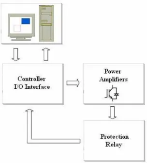
The testing system of distance relay consists in computer equipment, controller I/O interface and power amplifiers (Figure 1). In the computer equipment there is a simulator that provides several choices for the fault type. According the fault type it is generated the test signals that are converted in current and voltages references for the power amplifiers controllers. This is done using a microcontroller to connect the digital simulator to the power amplifiers.
The simulator inside the computer equipment it was developed in Matlab/Simulink allowing for testing and also evaluates the distance relay operating characteristic. This program communicates with a microcontroller in a bi-directional way. This allows to send information for the power amplifiers and at the same time to receive information from the protection relay.
III. MODELING THE POWER AMPLIFIER SYSTEM
The power amplifier system is composed by a current and voltage amplifier as presented in Fig. 2. The current amplifier is composed by a four wire three phase inverter with an output inductor filter. The voltage amplifier is composed by a four wire three phase inverter and an output LC filter.
Fig. 2. Power amplifier system.
The dynamic behavior of current amplifier is described by the following simplified state-space model (using the displayed state variables):
» » » ¼ º « « « ¬ ª 3 2 1 s s s i i i dt d = » » » » » » » » ¼ º « « « « « « « « ¬ ª − − − f l i l i l L R L R L R 0 0 0 0 0 0 » » » ¼ º « « « ¬ ª 3 2 1 s s s i i i + + » » » ¼ º « « « ¬ ª 3 2 1 0 0 0 0 0 0 γ γ γ » » » ¼ º « « « ¬ ª i i i V V V (1)
Where
γ
k is relay the internal resistance andk
γ
represent the states of the switches of the kth inverter leg, defined as:° ¯ ° ® − = + + OFF is S and OFF is S if , ) OFF is S and ON is S ( if , k k k k k 3 3 1 1 γ (2)
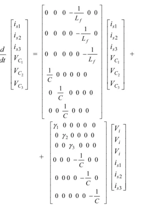
The dynamic behavior of the voltage amplifier is described by the following simplified state-space model (using the displayed state variables):
» » » » » » » » ¼ º « « « « « « « « ¬ ª 3 2 1 3 2 1 C C C s s s V V V i i i dt d = » » » » » » » » » » » » » » » » ¼ º « « « « « « « « « « « « « « « « ¬ ª − − − 0 0 0 1 0 0 0 0 0 0 1 0 0 0 0 0 0 1 1 0 0 0 0 0 0 1 0 0 0 0 0 0 1 0 0 0 C C C L L L f f f » » » » » » » » ¼ º « « « « « « « « ¬ ª 3 2 1 3 2 1 C C C s s s V V V i i i + + » » » » » » » » » » » ¼ º « « « « « « « « « « « ¬ ª − − − C C C 1 0 0 0 0 0 0 1 0 0 0 0 0 0 1 0 0 0 0 0 0 0 0 0 0 0 0 0 0 0 0 0 0 3 2 1 γ γ γ » » » » » » » » ¼ º « « « « « « « « ¬ ª 3 2 1 s s s i i i i i i V V V (3)
where
γ
krepresent the states of the switches of the kth
inverter leg, defined as (2).
To design a robust feedback loop for the current and voltage amplifiers, independent of power supply, semiconductors, and load parameters, variable-structure control is the technique of choice, since it is well adapted to the intrinsic variable structure of power converters [14, 15]. In particular, sliding-mode control techniques will be used.
For the current amplifier the controlled variables are the output line currents (is1,is2and is3). Therefore, from the state space model (1) of the current amplifier in the controllability canonical, it can be concluded that the controlled currents have a strong relative degree of one [16] (as only its first-time derivative contains the control variables γ1, γ2 and γ3). Therefore, according to the strong relative degree of each output variable (is1,is2and
3 s
i ), and considering the feedback errors as state
variables, the sliding surfaces ensuring the robustness of the closed loop system [17], are:
( )
i K(
i i)
, j 1,2,3However, in a practical system there is a frequency restriction of the switches. Therefore, the signals Ss
( )
ijcannot generate the control pulses to drive the switches at infinite switching frequency. Due to this problem the switches are controlled by a hysteresis comparator, in order to maintain the sliding surfaces Ss
( )
ij near zero. So the following control law is chosen as:( )
( )
( )
( )
( )
( )
° ° ° °
¯ °° ° °
®
¸¸ ¹ · ¨¨
© §
∆ < >
∆ − <
¸¸ ¹ · ¨¨
© §
∆ < <
∆ + >
=
• •
j s j
s j s
j s j
s j s
j
i S and i
S
or i
S if , off
i S and i
S
or i
S if , on
S
0 0
(5)
where ∆ is an arbitrary small quantity that defines the switching frequency and ripple current. Since the controller is designed to stabilize the system state, the following relation must be ensured:
( )
( )
( )
( )
° ¯ ° ®
∆ − < >
∆ + > <
• •
j s j
s
j s j
s
i S if , i
S
i S if , i
S
0 0
(6)
For the voltage amplifier the controlled variables are the output capacitor voltages (vC1,vC2 and vC3). Therefore, from the state space model (3) of the voltage amplifier in the controllability canonical, it can be concluded that the controlled voltages have a strong relative degree of two. Therefore, according to the strong relative degree of each output variable (vC1,vC2 and
3 C
v ), and considering the feedback errors as state
variables, the sliding surfaces ensuring the robustness of the closed loop system, are:
( )
(
)
3 2 1, , j
, dt dv dt dv k v v
v
Ss Cj Cjref Cj Cjref Cj
= ¸¸ ¹ · ¨¨
© §
− +
− =
(7)
where k is a parameter related to the time constant of the desired first order response of the capacitor voltages
(k>0). Since
dt dvCj
can be obtained using the inductor
and relay current, a new control law can be obtained:
( )
(
)
3 2 1, , j , C
i i dt dv k
v v
v S
j R L ref Cj
Cj ref Cj Cj s
= ¸ ¸ ¹ · ¨
¨ ©
§ −
− +
+ − =
(8)
The control law is chosen as (5) and the relation (6) must be ensured.
IV. EXPERIMENTAL RESULTS
A laboratory prototype of the power amplifier system for testing of distance relay operating characteristic was developed. Fig. 3 shows the prototype used in the experimental setup.
Fig. 3. Experimental setup.
In the computer there is a digital simulator of different fault types. The digital simulator was developed in Matlab/Simulink and generates the test signals for a microcontroller that convert in current and voltage references of the power converter amplifier. This system allows a steady state and dynamic testing of the relays.
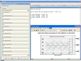
Fig. 4 shows one of the options of the program developed in Matlab/Simulink. In this option it is possible to define the amplitudes and angles of the voltage and currents that the power amplifier will apply to the relay.
Fig. 4. One of the options of the program developed in matlab/simulink.
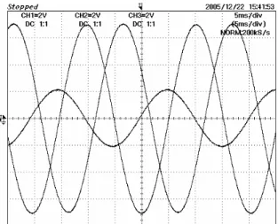
this case the type fault is a phase-to-earth fault. As expected in the phase fault the amplitude of the current is amplified and the amplitude of the voltage phase is reduced.
Fig. 5. Current references for no fault situation (1 div – 4 A).
Fig. 6. Current references for a steady state fault (1 div – 4 A).
Fig. 7. Voltage references for a steady state fault (1 div – 20 V).
In figure 8 it is presented the current reference and the correspondent output line current. As can be seen, the output current of the power converter amplifier follows the current reference.
Fig. 8. Current reference and correspondent output line current (1 div – 4 A).
Fig. 9 shows the current reference and the correspondent output line current, but for a dynamic fault. Again, it is possible to verify that the current amplifier follows the current reference.
Fig. 9. Current reference and correspondent output line current for a dynamic fault (1 div – 4 A).
The results presented in Figs. 8 and 9, where obtained for a 5 kHz switching frequency and a ripple of 0,3 A.
V. CONCLUSIONS
In this paper it was presented a power amplifier system for testing of distance relay operating characteristic. This testing system consists in computer equipment, controller I/O interface and power amplifiers. The power amplifier is based on two three phase inverters with a neutral wire. The output power currents and voltages are controlled by a fast sliding mode controller. A developed matlab/simulink digital simulator generates the test signals. This test signals are converted in current and voltage references using a microcontroller to connect the digital simulator to the power converter amplifier. Experimental results from a laboratory prototype have been presented and discussed.
REFERENCES
[1] A. Dierks, D. Kehrberg, “New algorithms to test distance relays,” Proceedings from the Seventh International Conference on Developments in Power System Protection, pp. 205-208, April 2001.
[2] CIGRE Working Group 34.10, “Analysis and Guidelines for Testing Numerical Protection Schemes,” Brochure Ref. No: 159, August 2000.
[3] W.O. Kennedy, B.J. Gruell, C.H. Shih, L. Yee, “Five years Experience with a New Method of Field Testing Cross and Quadrature Polarized MHO dIstance Relays, Part I Results and Observations,” IEEE Transactions on Power Delivery, vol. 3, pp. 879-886, July 1988.
[4] W.O. Kennedy, B.J. Gruell, C.H. Shih, L. Yee, “Five years Experience with a New Method of Field Testing Cross and Quadrature Polarized MHO dIstance Relays, Part II Three Case Studies,” IEEE Transactions on Power Delivery, vol. 3, pp. 879-886, July 1988.
[5] M. Kezunovic, Y.Q. Xia, Y. Guo, C.W. Fromen, D.R.Sevcik, “An Advanced Method for Testing of Distance Relay Operating Characteristic,” IEEE Transactions on Power Delivery, vol. 11, pp. 149-157, January 1996.
[6] C. F. Henville, “Type Tests on Distance Relays,” Proceedings from the Western Protective Relay Conference, October 1987. [7] Y.Q. Xia, , K.K.Li, A.K. David, “Adaptive Relay Setting for
Stand-Alone Digital Distance Protection,” IEEE Transactions on Power Delivery, vol. 9, pp. 480-491, January 1994
[8] P.R. Bishop, Z.Q. Bo, X.F. Shen, L. Denning, M. O'Keeffe, “On site dynamic testing of the power swing blocking element in distance relay,” Proceedings from the Seventh International Conference on Developments in Power System Protection, pp. 213-217, April 2001
[9] A.H. Abu Bakar, “Implementation of dynamic distance relay scheme evaluation testing guidelines using analogue and real time digital simulators,” Proceedings from the Power and Energy Conference, 2004. PECon 2004, pp. 158-164, November 2004 [10] W. Li-Cheng, L. Chih-Wen, C. Ching-Shan, “Modeling and
testing of a digital distance relay MATLAB/SIMULINK,” Proceedings of the 37th Annual North American Power Symposium, pp. 253-259, Octuber 2005.
[11] C.F. Henville, J.A.Jodice, “Discover Relay Design And Application Problems Using Pseudo-Transient Tests,” IEEE Transactions on Power Delivery, vol. 6, pp. 1444-1452, October 1991.
[12] M. Kezunovic, Y.Q. Xia, Y. Guo, C.W. Fromen, D.R. Sevcik, “Distance Relay Application Testing Using a Digital Simulator,”
IEEE Trans. on Power Delivery, Vol. 12, pp. 72-82, January 1997.
[13] M. Kezunovic, T. Popovic, D. Sevcik, H. DoCarmo, “Transient Testing of Protection Relays: Results, Methodology and Tools,” Proceedings of the International Conference on Power Systems Transients, pp. 1-6, Octuber 2003.
[14] Gao W., Hung J., “Variable structure control of nonlinear systems: a new approach” IEEE Transactions on Industrial Electronics, vol. 40, no. 1, pp. 45-44, 1993.
[15] J. Fernando Silva, “Sliding Mode Control Design of Drive and Regulation Electronics for Power Converters” Special Issue on Power Electronics of Journal on Circuits, Systems and Computers, vol. 5, no. 3, pp. 355-371, September 1995.
[16] Gao W., Hung J., “Variable structure control: A Survey” IEEE Transactions on Industrial Electronics, vol. 40, no. 1, pp. 2-22, February 1993.