Sensitivity analysis of the
seismic behavior of ancient
masonry buildings
DECLARATION
Name: Maria Francisca Nobre Meneses Email: [email protected]
Title of the
Msc Dissertation: Sensitivity analysis of the seismic behavior of ancient masonry buildings Supervisor(s): Nuno Leite Mendes, Paulo Barbosa Lourenço
Year: 2013
I hereby declare that all information in this document has been obtained and presented in accordance with academic rules and ethical conduct. I also declare that, as required by these rules and conduct, I have fully cited and referenced all material and results that are not original to this work.
I hereby declare that the MSc Consortium responsible for the Advanced Masters in Structural Analysis of Monuments and Historical Constructions is allowed to store and make available electronically the present MSc Dissertation.
University: Universidade do Minho, Portugal Date: 16th July 2013
Signature:
A
CKNOWLEDGEMENTS
The present thesis was developed within the framework of SAHC Erasmus Mundus Masters Course (www.msc-sahc.org). I would like to thank the European Union for providing me with the opportunity to be a part of the Advanced Masters in Structural Analysis of Monuments and Historical Construction (SAHC) program and for their financial support through the SAHC Consortium Scholarship. I would like to thank Prof. Paulo Lourenço and Prof. Nuno Mendes for the total availability and help during these past months and also to our colleague Leonardo Avila for the perfect help in a key moment.
I would like to express my gratitude particularly to Prof. Pere Roca and Prof. Luca Pelà of Universitat Politècnica de Catalunya for their help, guidance and dedication during my course work in Barcelona.
I would like to thank my colleagues in Barcelona for the friendship we created together and for all the wonderful moments we lived and that I will never forget.
Last, but for sure not the least, I would like to thank my family for the total support and to let me live and follow this dream. Thank you very much for your unconditional love.
A
BSTRACT
The study of the vulnerability of ancient buildings is receiving much attention in the recent decades due to the increasing interest in the conservation of the built heritage and the awareness that life and property must be preserved. The different types of masonry present common features that provide high seismic vulnerability to these buildings, such as the high specific mass, the low tensile strength, the low to moderate shear strength and the low ductility. In addition to the influence of the material properties, the seismic behavior of ancient masonry buildings depends on factors such as the geometry of the structure, connections between orthogonal walls, connections between structural walls and floors, connections between walls and roof, the foundation behavior, the stiffness of the floors and the behavior of the non-structural elements.
The present study aims at evaluating the variation on response of the structure varying the material and geometrical properties of the ancient masonry buildings. The response is obtained through the non linear dynamic and static analysis with time integration and is focused on the dynamic behavior of the masonry walls and timber floors. First, a reference numerical model is prepared according to the experimental tests carried out at shaking table. Then, a sensitivity analysis is carried out and the global behavior, the in plane and out-of-plane displacements of the masonry walls and the damage are compared with respect to the reference numerical model. Several parameters can be considered in the sensitivity analysis, namely: the number of floors, the aspect ratio of the spandrels, the aspect ratio of the lintels, the Young’s modulus of the masonry walls, the Young’s modulus of the floors. The expected major results coming from this work are the definition of the seismic response range of ancient masonry buildings taking into account the deviations on its properties, and the identification and quantification of the parameters that most influence its seismic performance.
R
ESUMO
O estudo da vulnerabilidade dos edifícios antigos está a obter atenção crescente durantes as últimas décadas devido ao crescente interesse na conservação do património construído e a consciência de que este deve ser preservado. Os diferentes tipos de alvenaria apresentam características comuns que propiciam a alta vulnerabilidade sísmica destes edifícios como a massa específica elevada, a baixa resistência à tração, a baixa a moderada resistência ao corte e a baixa ductilidade. Além da influência das propriedades do material, o comportamento sísmico de edifícios em alvenaria antiga depende de fatores tais como a geometria da estrutura, as ligações entre as paredes ortogonais, ligações entre as paredes e pavimentos, ligações entre paredes e telhado, a rigidez dos pisos e o comportamento dos elementos não-estruturais.
O presente estudo tem como objetivo avaliar a variação na resposta da estrutura quando se modifica as propriedades do material e propriedades geométricas dos edifícios de alvenaria antiga. A resposta é obtida através da análise dinâmica e estática não-linear com integração no tempo e é focado no comportamento dinâmico das paredes de alvenaria e pisos de madeira. Em primeiro lugar, um modelo numérico de referência é preparado de acordo com testes experimentais efetuados em mesa sísmica. Em seguida, uma análise de sensibilidade é efetuada e o comportamento global, o comportamento no plano e para fora do plano das paredes de alvenaria e os danos são comparados em relação ao modelo de referência. Vários parâmetros podem ser considerados na análise de sensibilidade: o número de andares, o rácio dos nembos, o rácio dos pilares, o módulo de deformabilidade das paredes de alvenaria, o módulo de deformabilidade dos pisos. Os principais resultados esperados provenientes deste trabalho são a definição da gama de resposta sísmica de edifícios antigos de alvenaria, tendo em conta os desvios em suas propriedades, bem como a identificação e quantificação dos parâmetros que mais influenciam o seu desempenho sísmico.
Palavras chave: Edifícios gaioleiros, comportamento sísmicos de edifícios de alvenaria antigos, análise dinâmica não linear
I
NDEX
1. Introduction ... 1
1.1 Framework and motivation ... 1
1.2 The gaioleiro building ... 3
1.2.1 Historical context ... 3
1.2.2 Description of the properties ... 7
1.3 Development and presentation of the dissertation ... 12
2. Seismic performance of ancient masonry buildings ... 13
2.1 Introduction ... 13
2.1 Out-of-plane behavior ... 16
2.2 In plane behavior and collapse ... 18
2.3 Diaphragms ... 20
2.4 Performed seismic analysis ... 22
2.4.1 Static Linear Analysis ... 22
2.4.2 Dynamic Properties ... 22
2.4.3 Non linear static analysis - Pushover ... 23
2.4.4 Dynamic non linear analysis – Time-History ... 25
3. Preparation of the numerical model ... 27
3.1 Introduction ... 27
3.2 Micro and macro modeling approach ... 27
3.3 Non linear macro modeling of the structure ... 28
3.3.1 Integration method ... 29
3.3.2 Time stepping ... 30
3.3.3 Iterative procedures ... 30
3.3.5 Material modeling... 33
3.4 Element modeling ... 35
3.5 Support conditions ... 36
3.6 Loads definition ... 36
3.6.1 Definition of permanent loads ... 36
3.6.2 Definition of seismic loads ... 37
3.7 Reference model ... 39
3.7.1 Reference model description ... 40
4. Reference model results ... 43
4.1 Introduction ... 43
4.2 Dynamic properties ... 43
4.3 Non linear static analysis ... 45
4.4 Non linear dynamic analysis ... 50
4.5 Comparison between non linear dynamic and static analysis ... 58
5. Sensitivity Analysis ... 61
5.1 Introduction ... 61
5.2 Numerical results and analysis ... 62
5.2.1 Variation of the number of floors ... 62
5.2.2 Variation of the spandrel ratio ... 68
5.2.3 Variation of the Young’s modulus of the walls (Ewalls) ... 75
5.2.4 Variation of the Young’s Modulus of the floors (Efloors) ... 78
6. Conclusions ... 89
6.1 Final conclusions ... 89
6.2 Proposal of future work ... 91
L
IST OF
F
IGURES
Figure 1 – a) Pré-Pombalino buildings in Lisbon; b) Example of Pombalino building in Lisbon. ... 2
Figure 2 – High quality gaioleiro building located in Avenida da Liberdade, Lisbon. ... 2
Figure 3 – Eugénio dos Santos’ Urban plan of the new part of Lisbon after the Earthquake (Ordem dos Engenheiros, 2013) ... 3
Figure 4 – Pombalino building with and without the masonry enclosure walls to observe the wooden structure. (Paula & Cóias, 2006)... 4
Figure 5 – a) Details of the floors and walls (gaiola). b) Santo André’s Cross (Appleton J. , 2003) ... 4
Figure 6 – Distribution of the Lisbon’ Building stock typologies. (Cardoso, Lopes & Bento, 2003) ... 5
Figure 7 – Examples of Gaioleiro building in Lisbon. ... 6
Figure 8 – Summary of Lisbon’s building stock. (Simões & Bento, 2012) ... 7
Figure 9 – Plan of different types of gaioleiro building. a) Narrow front façade (one apartment per floor); b) Wide front façade (example with two apartments per floor); c) Corner building. (Adapted from Andrade (2011)). ... 8
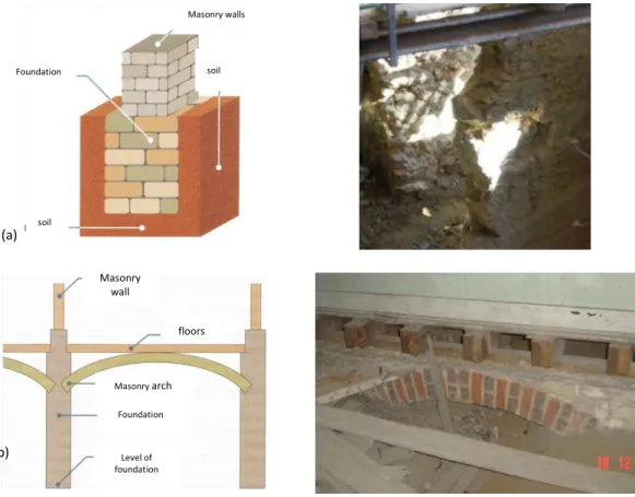
Figure 10 – Types of foundations. a) Direct foundations; b) Semi-direct foundations using arches. ... 9
Figure 11 – Wall composition. a) Exterior rubble stone masonry wall; b) Back façade made with solid brick masonry. c) Reduction of the thickness along the height (dimensions in meters). (Andrade, 2011) ... 10
Figure 12 – Interior walls. a) Interior wall made with brick masonry; b) Lath and plaster walls (Appleton J. , 2003)... 10
Figure 13 – Steel frame flooring. a) Steel I profiles; b) Brick masonry disposed in vaults (Appleton J. , 2005)... 11
Figure 14 – Types of pavement-wall connections. a) Insertion of timber joist at the pocket of the wall; b) Steel anchor; c) Connection with rim joist. (Appleton J. , 2005) ... 11
Figure 15 - Identification of macro elements’ structural elements. (D'Ayala & Novelli, 2010) ... 14
Figure 16 - In plane collapse mechanisms of piers. a) Rocking b) Sliding c) Diagonal tension d) Toe crushing. (Yi, 2004)... 15
Figure 17 - Schematic spandrel loading. (Gattesco, Clemente, Macorini, & Noè, 2008) ... 16
Figure 19 – Example of overturning of the façade. a) Cathedral of San Paolo in Mirabello, Italy after the May 20,
2012 Emilia Romagna earthquake. b) Church of San Martino in Sant’Agostino, Italy (Parisi & Augenti, 2013).... 17
Figure 20 - Out-of-plane failure mechanisms for unrestrained walls. (D'Ayala & Novelli, 2010) ... 18
Figure 21 – In plane damage on piers. ... 19
Figure 22 – In plane damage on spandrels. (Beyer & Mangalayhu, 2013) ... 20
Figure 23 - In plane behavior of masonry walls. (Adapted from FEMA 306 (1998)) ... 20
Figure 24 – Examples of wooden layout floors. (Brignola & Podestà, 2008) ... 21
Figure 25 – Behavior in functions of connections links between walls and type of floors. ... 21
Figure 26 – Modeling masonry types: a) detailed micro-modeling; b) simplified micro-modeling; (c) macro-modeling. (Zucchini & Lourenço, 2004) ... 28
Figure 27 –Regular Newton-Raphson iterative method. (TNO DIANA, 2011) ... 31
Figure 28 - Modified Newton-Raphson iterative method. (TNO DIANA, 2011) ... 31
Figure 29 – Linear Stiffness iterative method. (TNO DIANA, 2011) ... 32
Figure 30 – Types of possible hysteretic modeling (Deierlein, Reinhorn, & Willfor, 2010). ... 33
Figure 31 – Damage model considered for the modeling of masonry walls. ... 34
Figure 32 – The eight element node. (TNO DIANA, 2011) ... 35
Figure 33 – The beam element.(TNO DIANA, 2011). ... 36
Figure 34 – Seismic zonation for Mainland Portugal: a) Far-field earthquake (type 1); b) Near-Field earthquake (type 2)... 37
Figure 36 – Acceleration response spectra for far-field and near-field earthquake in Lisbon. ... 38
Figure 37 – Signals applies to the structure. a) North-South direction; b) East-West direction. ... 39
Figure 38 – Non-strengthened mock-up used in the shaking table of LNEC. (Mendes, 2012) ... 40
Figure 39 – Reference Model. a) Model and mesh of the walls and floors; b) Geometry. ... 41
Figure 40 - Modes and frequencies obtained for the reference model. ... 44
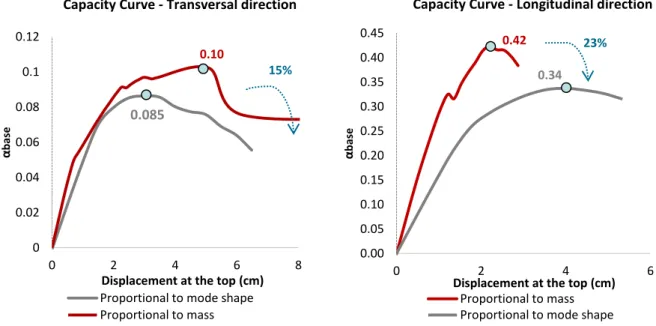
Figure 41 – Capacity curves obtained with the two different methods in each direction. a)Force proportional to the mass; b) Force proportional to the first mode. ... 46
Figure 43 – Capacity curve and identification of failure points on the Transversal direction of the reference
model... 47
Figure 44 – Deformation and location of cracks. a)First cracks; b)cracks on the 3rd floor; c)cracks on 4th floor and base piers. ... 48
Figure 45 – Failure mechanisms associated with the façade. a) Out-of-plane of the façade; b) Detachment of the façade. ... 48
Figure 46 - Capacity curve and identification of failure points on the longitudinal direction of the reference model... 49
Figure 47 - Deformation and location of cracks. a)1st Vertical crack; b) Crack at the bottom. ... 49
Figure 48 – Pattern and location of the diagonal crack on the gable wall. Rotation center of the macro element. ... 50
Figure 49 – a) Out-of-plane displacement of the North façade; b) Inter-storey Drift of the North Façade. ... 51
Figure 50 – a) Out-of-plane displacement of the East gable wall; b)Inter-storey Drift of the East Gable wall. .... 51
Figure 51 – a) In plane displacement of the North façade; b) Inter-storey Drift of the North Façade. ... 52
Figure 52 – a) In plane displacement of the East gable wall; b) Inter-storey Drift of the East Gable wall. ... 53
Figure 53 – Envelope of αb results in the transversal direction. ... 54
Figure 54 - Envelope of αb results in the longitudinal direction ... 54
Figure 55 - Principal Strains (external surfaces of the walls) in the reference model. a) 100%Earthquake load; b) 150%Earthquake load... 55
Figure 56 – Maximum Principal strains on the interior surface of the masonry walls for 100%Earthquake load. 56 Figure 57 – Classification of damage on masonry buildings to be used in the calculation of EMS 98 intensities. (Simões & Bento, 2012) e (Lopes M. , 2008) ... 57
Figure 58 –DNL envelopes for different seismic intensities and grades of damage according to the European Macroseismic Scale 1998. ... 57
Figure 59 - Comparison between the pushover and time-history analysis’ envelopes in the transversal direction. ... 58
Figure 60 - Comparison between the pushover and time-history analysis’ envelopes in the longitudinal direction. ... 59
Figure 61 - Principal Strains (external surfaces of the walls) in the reference model for 300% Earthquake. a)
Damage on the façade; b) Damage on the gable wall. ... 60
Figure 62 – Model with 5 floors. a) Model and mesh of the walls and floors; b) Geometry. ... 63
Figure 63 – Model with 6 floors. a) Model and mesh of the walls and floors; b) Geometry. ... 63
Figure 64- Mode Shapes of model with 5 floors and 6 floors. ... 65
Figure 65 - Out-of-plane displacements at middle of the walls for models with different number of floors. a) Out-of-plane displacement of the North façade; b) Out-of-plane displacement of the East gable wall. ... 66
Figure 66 – In plane displacements for models with different number of floors. a) In plane displacement of the North façade; b) In plane displacement of the East gable wall. ... 66
Figure 67 - Envelope of the response obtained from the non linear dynamic analysis in the transversal direction. Variation of the number of floors. ... 67
Figure 68 - Envelope of the response obtained from the non linear dynamic analysis in the longitudinal direction. Variation of the number of floors. ... 67
Figure 69 – Maximum tensile principal strains obtained from the dynamic non linear analysis. a) Model with 5 floors; b) Model with 6 floors. ... 68
Figure 70 – Model with short spandrels. a) Model and mesh of the walls and floors; b) Geometry. ... 69
Figure 71 – Model with slender piers. a) Model and mesh of the walls and floors; b) Geometry. ... 69
Figure 72 – First mode shapes of model with short spandrels and model with slender piers. ... 71
Figure 73 – plane displacements at the middle of the walls for variation of the spandrel ratio. a) Out-of-plane displacement of the North façade; b) Out-of-Out-of-plane displacement of the East gable wall. ... 72
Figure 74 – In plane displacements for variation of the spandrel ratio.a) In plane displacement. of the North façade; b) In plane displacement of the East gable wall. ... 73
Figure 75 - Envelope of the response obtained from the non linear dynamic analysis in the transversal direction: Variation of the spandrel ratio. ... 74
Figure 76 - Envelope of the response obtained from the non linear dynamic analysis in the longitudinal direction: Variation of the spandrel ratio. ... 74
Figure 77 – Maximum tensile principal strains obtained from the dynamic non linear analysis. a) Model with short spandrels; b) Model slender piers. ... 75
Figure 78 –– Out-of-plane displacements at the middle of the walls for models with variation of the Young’s modulus of the walls. a) Out-of-plane displacement of the North façade; b) Out-of-plane displacement of the East gable wall. ... 76 Figure 79 – In plane displacements for models with variation of the Young’s modulus of the walls. a) In plane displacement of the North façade; b) In plane displacement of the East gable wall. ... 76 Figure 80 - Envelope of the response obtained from the non linear dynamic analysis in the transversal direction. Variation of the stiffness of the masonry walls. ... 77 Figure 81 - Envelope of the response obtained from the non linear dynamic analysis in the longitudinal direction. Variation of the Young’s modulus of the masonry walls. ... 77 Figure 82 – Maximum tensile principal strains obtained from the dynamic non linear analysis. a) Model considering Ewalls=0.5 GPa; b) Model considering Ewalls=4.0 GPa ... 78 Figure 83 – Variation of the floor Young’s modulus. a) In plane displacement of the North façade; b) In plane displacement of the East gable wall. ... 80 Figure 84 – Variation of the floor Young’s modulus. a) Out-of-plane displacement at the middle of the North façade; b) Out-of-plane displacement at the middle of the East gable wall. ... 81 Figure 85 - Envelope of the response obtained from the non linear dynamic analysis in the transversal direction. Variation of the E of the floors. ... 81 Figure 86 - Envelope of the response obtained from the non linear dynamic analysis in the longitudinal direction. Variation of the E of the floors. ... 82 Figure 87 – Maximum tensile principal strains obtained from the dynamic non linear analysis. a) Reference Model; b) Model without floors; c) Model 2xthickness; d) Model with RC slab. ... 83 Figure 88 - Envelope of response of the model without floors. a) Transversal direction; b) Longitudinal direction. ... 84 Figure 89 - Envelope of response of the model with reinforced concrete slab. a) Transversal direction; b) Longitudinal direction. ... 85 Figure 90 - Envelope of response of the model with two times thickness floor. a) Transversal direction; b) Longitudinal direction. ... 85 Figure 91 - Envelope of response of the model without floors. a) Transversal direction; b) Longitudinal direction. ... 86 Figure 92 - Envelope of response of the model with two times thickness floor. a) Transversal direction; b) Longitudinal direction. ... 87
Figure 93 - Envelope of response of the model with RC slab. a) Transversal direction; b) Longitudinal direction. ... 87
1. I
NTRODUCTION
1.1 F
RAMEWORK AND MOTIVATIONTourism is continually becoming more important to the society in general and to the economy of cities and countries in particular. As a consequence, the importance of preserving and keeping the old city centers and other building heritage is obvious. It is estimated that the existing building stock in Lisbon is half composed by ancient masonry buildings, and more than 60% of them need structural intervention and should be evaluated according to their seismic vulnerability. (Simões & Bento, 2012)
In 1755 Lisbon suffered from a catastrophic earthquake, destroying a significant part of the city. Despite the present reduced activity, the seismic events are recurrent and so a strong earthquake can take place again in Lisbon. The seismic risk is related with the possible economical losses and causalities, and it is determined taking into account the seismic hazard, the seismic vulnerability of buildings and the assets exposure. The seismic hazard is associated directly with the tendency of the region for the occurrence of earthquakes. In Portugal the trend of the seismic hazard is generally higher in the South that in the North. The seismic vulnerability of buildings is related to the structural damage caused by a given earthquake. The assets exposure is associated with the presence of more or less vulnerable constructions depending, consequently, on the population density and on the economic development of the region. Since the seismic risk is always present, because it is not possible to have null seismic danger, safety cannot be understood as the absence of risk but shall be referred to as “acceptable risk”. As pointed in Simões & Bento (2012), the correct determination of the seismic vulnerability is more important or severe than the uncertainties related to the seismic hazard (this last one is not possible to control). The seismic vulnerability is depending on the properties of the constructions, which can be analyzed, for example, depending on the period which they were built.
The earthquake of 1755 had an important role on the transformation of the Lisbon’ building stock as it leads the way to the appearance of a new masonry type of building – The Pombalino. Presently there are three types of masonry buildings: Pré-Pombalino (built before 1755), Pombalino (built between 1755 and 1840) and
Gaioleiro buildings (from 1870 to 1940). In Figure 1 an example of Pré-Pombalino and Pombalino buildings in
Lisbon is presented. Later, the appearance of the concrete and the codes for anti-seismic constructions was another crucial event and changed completely the seismic vulnerability of the new buildings: Placa (“slab”) buildings appeared around 1930 with the inclusion of concrete floors (stiff diaphragms) and after frame reinforced concrete buildings. For determine quantitatively the seismic vulnerability of ancient masonry buildings it is necessary to do the qualitative analysis of it by establishing: the date of construction, typology, materials, construction methods, the structural system of that period and the current state of conservation. In
the case of historical constructions, all the uncertainties and variability regarding the material characteristics, influence of unknown previous phenomena (e.g. soil settlements) and the possible incomplete data on alterations and repairs carried out in the past, make the seismic vulnerability difficult to predict.
Figure 1 – a) Pré-Pombalino buildings in Lisbon; b) Example of Pombalino building in Lisbon.
The scope of the thesis is to assess the influence of some of the ancient masonry buildings’ properties on their seismic vulnerability. The objective is to change some parameters and evaluate its influence on the seismic performance of this type of buildings, namely on the in plane and out-of-plane response of the masonry walls and damage. The present study will be specially focused on the sensitivity analysis of the masonry gaioleiro buildings, which exist in a high number in a “noble” part of the Portuguese capital (Figure 2). This building typology presents some aspects of the Pombalino buildings, but they do not have a good construction quality and so the city grew fast based, generally, on poor masonry buildings that are still now in use. Furthermore, this thesis aims to evaluate the application of modern techniques of structural analysis (pushover analyses), currently used for reinforced concrete and steel structures, to ancient masonry buildings with flexible floors.
1.2 T
HE GAIOLEIRO BUILDINGThe gaioleiro buildings are currently not fitting the present housing requirements of the Lisbon inhabitants and many of them are in a state of severe degradation. As a consequence, a lot of them suffered in the last 90 years some transformations and were already strengthened in a way that sometimes where not the most suitable and some others present major security problems for its residents.
1.2.1 Historical context
On November 1st (all Saint’s day) 1755, Lisbon woke up with an earthquake of magnitude of about 9 (Richter magnitude scale), which would prove to be one of the deadliest earthquakes to ever strike Europe. This incident destroyed almost all the city, including its building stock, and other dozens of other Portuguese villages along the coast. Around 11am the first of three tsunami waves struck Lisbon which, despite only of approximately 5m high, funneled into the city via the Tagus river estuary causing great damage and loss of life. The Tsunami waves arrived to the UK, Northern Africa, and the Caribbean. Most of the city’s residents were gathered in churches and cathedrals on that Sunday morning, when a little after 9:30 am a terrible rumbling noise was followed moments later by intense shaking that lasted several minutes, collapsing most of the city’s buildings. However, the worst was yet to come. Fires spread quickly among the ruins, engulfing the city of Lisbon, turning the city into a hell that would burn for days. Following this incident and taking into account the necessity to rebuild the city in an orderly way, Marquês de Pombal, secretary of state on that time, commissioned Eugénio dos Santos and Carlos Mardrel to design a new urban plan for the city, based on a regular and complex block grid, with wide streets, connecting the two main squares – Rossio and Terreiro do Paço (Figure 3). The new urban plan included also rigid directions related with architect project design of the buildings such as the number of floors, area, façade design, etc.
The typical Pombalino building have four floors: the first with windows and balconies, the second and third with simple windows, the last floor is an attic and the ground floor is occupied with shops, as shown in Figure 4. The most innovative and important aspect of this new building typology was the insertion of a resisting wooden structure inside the walls giving seismic resistance to the building (Figure 5). This “wooden cage”, whose structure is based on the “frontal” walls creating an orthogonal grid that receives the joist’s floor. This kind of wood cage (gaiola) is essential to the locking of the structure and improves the seismic behavior of the building. The vertical, horizontal (beams) and diagonal (struts) joists, form a kind of wooden crosses called
Santo André. All these elements are interconnected by assemblies and nailing fixation and are filled after with
solid brick masonry, ceramic or irregular stone fragments and lime mortar. These walls have thicknesses between 15 and 22 cm and the woods commonly used in its manufacture are oak and pine.
Figure 4 – Pombalino building with and without the masonry enclosure walls to observe the wooden structure. (Paula & Cóias, 2006)
Figure 5 – a) Details of the floors and walls (gaiola). b) Santo André’s Cross (Appleton J. , 2003)
Starting from the end of the 19th century, Lisbon experienced a great urban expansion, especially to the North part of the city, contradicting the city tendency of growth parallel to the river. This expansion followed a plan developed by Ressano Garcia, which was inspired in a way by the new Parisian boulevards, with avenues with central lanes divisions with floors and trees and wide streets. The expansion plan was very pragmatic; Ressano Garcia adapted the plan to fit in the terrain, included existing streets in its grid and changed the scale of blocks according to the topography of the land.
After more or less one century, the memory of the earthquake started to fade. The significant increase of population in the mid of 18th century and the rapid growth of the city made possible the appearance of a new building typology called gaioleiros. The gaioleiro buildings are associated with the construction of Bairro de Camões occupying the hill on the east side of Santa Marta Street and Avenidas Novas adjacent to Fontes Avenida Pereira de Melo and Avenida da República (Figure 6). The buildings were aggregated in blocks with interior yards and surrounded by a grid of secondary streets, wider than the streets of the Pombalino downtown. (Simões & Bento, 2012)
Figure 6 – Distribution of the Lisbon’ Building stock typologies. (Cardoso, Lopes & Bento, 2003)
The gaioleiro buildings were built between 1870 and 1930 in a quicker way, inexpensively and with guaranteed money return, and are clearly labeled as low quality buildings. This denomination has the objective to expose the considerable structural alterations done in the design of the buildings comparing with those from the previous period; the gaiola Pombalina was completely changed (the timber structure started to be simplified and the rubble masonry infill replaced by industrial masonry bricks) and has no longer the necessary quality to proper resist to an earthquake. The quality of the materials used and the construction techniques adopted were also inferior to the ones used in the Pombalino buildings.
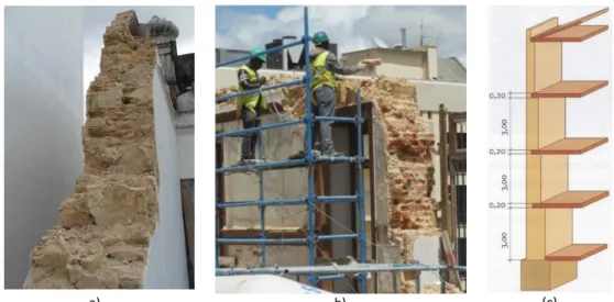
Figure 7 – Examples of Gaioleiro building in Lisbon.
These buildings have physic and constructive characteristics that distinguish them from others Lisbon’s building typologies, some of them are presented in (Appleton J. , 2003). There is a greater freedom than in the
Pombalino in respect to the windows’ dimension and stonework, as example the dimensions of the windows
increased and the spandrels got smaller. It is possible to use on the same floor simultaneous windows and balcony doors. The decorations of the façades appear to have some French influence. The balconies and
marquises are made with a very slender steel structure with decorative and functional properties. These
elements present a mix floor solution constituted by steel I or T inverted beams and masonry brick vault connected by a layer of lime mortar or cement. In the rear façade is common to find metallic stairs and there are large shafts for light and ventilation of the interior divisions. The stairs are located, approximately, at the central position of the plan, resulting in some structural symmetry. Another characteristic is common lack of structural continuity, in which connections between the orthogonal bearing walls and between the load-bearing walls and the floors are not adequate. According to Appleton (2005), the area of implantation varies from around 127.8 m2 to 529.0 m2, with widths ranging between 6.5 m and 15.2 m, and depths between 16.5 m and 28.0 m. The gaioleiro buildings are usually semi-detached and the pounding should be considered when the adjacent buildings present different heights or if the separation distance is not large enough to accommodate the displacements. It is noted the “block” effect is usually beneficial and provides higher strength to the building, as shown in Ramos & Lourenço (2004). A detailed description of the structural elements of these buildings will be presented next.
The gaioleiro building characterize a transition period from the anti-seismic practices and the modern reinforced concrete frame buildings, passing through the Placa buildings which include both bearing masonry walls and concrete floors. A summary of the evolution of the Lisbon’s building stock is presented schematically in Figure 8.
Figure 8 – Summary of Lisbon’s building stock. (Simões & Bento, 2012)
1.2.2 Description of the properties
Some distinguishable architectonic properties are the decoration of the front façade including some Art
Nouveau details or with a stripe of tiles, windows with labored stone frames. The general configuration of a gaioleiro apartment is narrow and long. If the façade’s width was at least 15m one building would have two
apartments for floor and between four and seven floors. There are four distinguishable types of gaioleiro buildings (Figure 9):
1. Small to medium size buildings with narrow façades, one apartment per floor, lateral shaft and lateral stairs;
2. Large buildings size with wide front façades and one big apartment per floor;
3. Large buildings with wide front façades, a central stair, two lateral shaft (eventually another one central) and two apartments per floor.
4. Large buildings located in corners with two or more shafts, central stairs and two or more apartments per floor.
a) b)
(c)
Figure 9 – Plan of different types of gaioleiro building. a) Narrow front façade (one apartment per floor); b) Wide front façade (example with two apartments per floor); c) Corner building. (Adapted from Andrade (2011)).
1.2.2.1 Foundations
The soil where there is a significant presence of gaioleiro buildings is mostly composed by sandy-clay soils with low resistance rocks. The gaioleiro buildings were commonly supported on caissons or on arches structure (Figure 10b). When the adequate foundation soil was more than three meters deep, they could be supported on direct foundation made with continuous walls in limestone masonry solid grounded (Figure 10a). If it was possible to use direct foundations, the dimensions would depend on the characteristics of the soil and dimensions of the wall - on the façades usually between 1.10 to 1.50m and below the gable and light-shaft walls around 0.60 to 0.70 m thick (Appleton, 2003).
Figure 10 – Types of foundations. a) Direct foundations; b) Semi-direct foundations using arches.
1.2.2.2 Walls
The load-bearing walls, as the exterior walls, were built in rubble stone masonry with lime mortar and sand (Figure 11a) and can present a reduction of thickness in elevation of the building (Figure 11c). It is common to find variation of the main walls’ thickness in height for economic reasons and reduction of the self-weight of the walls. A weaker out-of-plane performance of the masonry walls is prone to happen in gaioleiro buildings, due to the poor connection between the walls and floors, and between orthogonal masonry walls.
The front façade walls are typically 0.60 to 1.0 m thick on the ground floor, with a decreasing thickness with the elevation of the building, resulting in rooftop walls with 0.30 to 0.40 m of thickness. The back façade walls were
(a) (b) Foundation soil Masonry walls soil Masonry wall floors Masonry arch Foundation Level of foundation
usually 0.50 to 0.60 m thick. Vertical and horizontal timber struts were used to reinforce the masonry walls around door and window openings. However, the experience has demonstrated that often these elements do not exist.
.
a) b) (c)
Figure 11 – Wall composition. a) Exterior rubble stone masonry wall; b) Back façade made with solid brick masonry. c) Reduction of the thickness along the height (dimensions in meters). (Andrade, 2011)
A new wall configuration was adopted and resulted from the simplification of the Pombalino cage. The truss elements of the frontal walls were removed and the rubble infill was by brick masonry, solid on the lower floors and hollow on the upper, or by lath and plaster for the partition walls. The partition walls, which show almost no load-bearing capacity, were made by vertical timber strips with approximately 0.15 m large and horizontal timber square strips filled on the breaks by rubble masonry, resulting in walls with 0.10 to 0.15 m thickness (Figure 12 a) (Simões & Bento, 2012).
a) b)
Figure 12 – Interior walls. a) Interior wall made with brick masonry; b) Lath and plaster walls (Appleton J. , 2003)
The side walls, or gable walls, are frequently shared by adjacent buildings and are interrupted by shafts, in order to provide natural light and ventilation to the interior rooms. Ventilated masonry boxes on the ground floor prevented the rising moisture from the soil and the rotten of the interior wooden structures (Simões &
Bento, 2012). The shaft and gable walls were originally built in rubble stone masonry with 0.40 to 0.50 m thickness, but later evolved to bricks masonry walls, with 0.30 to 0.15 m thickness.
1.2.2.3 Floors
The gaioleiro buildings can have floors with metallic frame, applied in compartments with high moisture like the kitchen and bathrooms, or timber frame in the other zones. The most common are the wooden ones used in the entire floor.
The steel floors (Figure 13) were gradually adopted on the kitchen, bathrooms and balconies and were built with iron beams in shape of I or T profile and brick masonry disposed in vaults, interconnected by air lime mortar or cement. The use of steel flooring became popular, due to the supposed superior durability of iron in relation to wood, especially in areas in contact with water. However, due to the insufficient protection of these elements against corrosion, this solution turned out to be equally vulnerable (Simões & Bento, 2012).
a) b)
Figure 13 – Steel frame flooring. a) Steel I profiles; b) Brick masonry disposed in vaults (Appleton J. , 2005).
The floors with timber frame are more common and are composed of a grid (usually pine wood) of timber joists, floorboards and ring joists, over which board flooring is laid. The width and height of the timber joist ranges, from 0.07 m to 0.08 m and from 0.16 m to 0.22 m, respectively, and the spacing varies from 0.20 m to 0.40 m. The final floorboards, with more or less 0.02 m of thickness, are placed over the joists. Three types of connections between floors and walls can be found (Appleton J. , 2005):
a) Insertion of the timber joist into a pocket of the wall with only a few centimeters of support (Figure 14 a); b) incorporation of steel anchors, nailed to the timber joists and embedded into the walls (Figure 14 b); c) In case of pavements with joists the connection includes the joist and an anchorage (Figure 14 c);
Figure 14 – Types of pavement-wall connections. a) Insertion of timber joist at the pocket of the wall; b) Steel anchor; c) Connection with rim joist. (Appleton J. , 2005)
1.2.2.4 Roof
In the major part of this kind of ancient masonry buildings, the roof structure is inclined and made of timber, allowing the use of the attics – mansard roof. In order to take the most advantage of this space the slope of the roof increased in comparison to the typical Pombalino roof. The use of these spaces is made independently of the rest of the building’ structure, since the interior space was divided by a timber truss structure independent from the rest of the building, as the compartment walls were not connected with the interior building structure. The loads transmission from the roof structure to the resistant walls could be done in two ways: through direct support of the trusses on the walls, for the support of trusses on stone cantilevers, or using a transition beam to promoted a better distribution of the loads on the wall.
1.2.2.5 Stairs
The staircases were made in pine wood and supported in the structural walls. They could be located in the center of the building, usually around a central hall, lighted and ventilated by skylights, or located along the side of the gable wall, depending on the size of the building.
The exterior steel frame stairs appear at a later stage by imposition of the municipality that, in 1892, forced the implementation of stairs overlapping the rear façade to be used in fire situations.
1.3 D
EVELOPMENT AND PRESENTATION OF THE DISSERTATIONThe present study is divided in 6 chapters. The first chapter aims to make the introduction to the gaioleiro typology and its main properties and characteristics. A brief historical overview of the 1755 Lisbon’s earthquake is presented. Through the second chapter a general overview of the seismic behavior of masonry structures is provided. Furthermore, a brief presentation of the types of seismic analysis performed on the current thesis is made. In the third chapter the preparation of the numerical model in the program Diana is discussed and the chapter is ending with the presentation of the reference model. The fourth chapter is dedicated to the reference model’s results: it starts with the analysis of the dynamic properties and it is followed by the discussion of the results obtained with the non linear dynamic analysis and non linear static analysis. Furthermore, a discussion about the application of the pushover method and comparison between these two non linear analyses is carried out. The results and conclusions about variations imposed to the reference model is accessible in chapter five. The objective is to determine the properties that most influence the seismic behavior of this type of buildings. As done in the previous chapter, the comparison between the models was made applying the non linear dynamic analysis and non linear static analysis.
The main conclusions of the case study as well as recommendations are presented in the final Chapter (sixth chapter). The chapter also includes a short survey of opportunities for further research.
2. S
EISMIC PERFORMANCE OF ANCIENT
MASONRY BUILDINGS
2.1 I
NTRODUCTIONAncient buildings where mostly made of masonry, which is a composite material of units (brick, block, stone) and mortar (clay, cement, chalk, lime). The properties and resisting characteristics of the masonry are depending on the properties of the constituents (units, mortar and their interfaces) and the construction techniques which depend also on the builder. Despite the dispersion of masonry buildings’ characteristics, it is possible to point out the common features of the masonry mechanical behavior: high specific mass, low tensile strength, low to moderate shear strength and low ductility (quasi-brittle behavior), anisotropic structural material, non-homogeneous and non-elastic (Mendes, 2012). From the previous characteristics it is possible to conclude that masonry performs well when working in compression, but has a lower capacity to bear shear and tensile stresses. These stresses have to be sustained by the walls, taking advantage of the self-weight of the structure and the friction between stones and mortar. Masonry walls have a good performance in its plane, supporting the vertical axial loads, which only introduce compressive stresses on them. However, when the walls are subjected to horizontal excitations the vertical loads will tend to bend the walls, increasing the tensile and shear stresses, which this material is practically unable to resist (Simões & Bento, 2012). The seismic vulnerability of masonry buildings is extremely dependent on the load-bearing walls, which are normally arranged in orthogonal planes, and connections between the floors and the walls. Furthermore, the stiffness of the floors have a high influence on the seismic vulnerability of the buildings. In general, the ancient masonry buildings present flexible floors.
The mechanical properties, which determine the load-bearing capacity and deformability of masonry walls are: the compressive strength of masonry fc, the tensile strength of masonry ft, the Young’s modulus E, the shear
modulus G, and initial shear strength under zero compressive stress fvk0. These parameters can be determined
by means of experimental tests or by equations as a function of the mechanical properties of the masonry components. The compressive strength of the units is ranging between 5 MPa and 130 MPa, and the mortar strength normally between 1.5 to 3.5 MPa. Table 1 presents the typical masonry mechanical properties.
Table 1 – Mechanical properties s of masonry. (Tomazevic, 1999)
Stone Masonry Brick Masonry Compressive strength [MPa] 0.3-0.9 1.5-10.0
Tensile strength [MPa] 0.08-0.21 0.10-0.70 Young’s modulus [MPa] 200-1000 1500-3800
Shear modulus [MPa] 70-90 60-165
The elements that most influence the seismic performance of the structural walls are shown in Figure 15. The walls, both interior and external, are cut by openings like windows, doors and arches that will define the spandrels, piers, pillars and lintels. The effect of the presence of openings on the diagonal shear failure will be studied in the present thesis; wall openings weaken the in plane resistance of walls by decreasing the size of its cross-section. These openings also cause stress concentrations on the corners, which promote the formation of diagonal cracks. These cracks start at the opening corners and progress in a zig-zag trend through the mortar joints or diagonally through the masonry units in the wall. This cracking can further reduce wall capacity. Shariq et al. (2007) analyzed the influence of wall openings in the seismic response of a single storey and with only one room masonry building by changing the dimensions of the building in plan. The following conclusions were drawn: a) the increase of the aspect ratio of a room with openings, by keeping one side fixed, results in the increasing of the maximum principal tensile stress and maximum shear stress; b) increasing the openings in a wall results in high stresses around openings, the maximum principal tensile stress occurs along the short wall and the maximum shear stress occurs in the long wall.
Figure 15 - Identification of macro elements’ structural elements. (D'Ayala & Novelli, 2010)
The openings define the geometry of the piers and spandrels, which provide the gravity and lateral load resisting systems. Thus, their properties and dimensions influences highly the in plane failure of the masonry walls. The damage can appear both on spandrels and piers, however, the behavior is different since the axis of the spandrel is horizontal and in the piers is vertical. Furthermore, the normal stress in the piers is much higher due to the vertical loads.
According to (FEMA 306, 1998) piers can have considerable deformability and ductility if certain failure mechanisms prevail. Axial stress, aspect ratio, boundary conditions, and relative strength between mortar joints and units determine the failure mechanisms of masonry piers (Yi, 2004). Depending on the parameters described before there are four typical failure modes of masonry walls in their plan, as shown in Figure 16:
Rocking failure –As refered on (FEMA 306, 1998) the wall-pier rocking behavior mode, the wall or pier acts as a
rigid body rotating about the toe after flexural cracking develops at the heel. The rocking mode typically occurs when material shear capacity is high, piers are slender, and compressive stress is low. Post cracking deformations can be large and relatively stable for many cycles;
Shear sliding failure –when the shear force in a pier is larger than the bed joints shear strength, sliding cracks develop in the bed joints at one end of the structural element and the failure takes place;
Diagonal cracking (shear failure) – the damage of this type of failure is shown by the development of stepped
diagonal tension cracks, propagating along the mortar bed joints and head joints in the case of strong unit-weak mortar masonry, or straight cracks going through the units if the strength of the unit is similar to that of the mortar (Yi, 2004).
Toe crushing - the initial cracking of the masonry in tension (in the bed joints for piers, in both head joints and bricks in spandrels) and the subsequent crushing of the diagonal opposite compressed corners of the element. Since the toe of a pier is the zone with higher concentrated compressive stress, the compressive failure will develop in this area.
Figure 16 - In plane collapse mechanisms of piers. a) Rocking b) Sliding c) Diagonal tension d) Toe crushing. (Yi, 2004)
Rocking and sliding failure modes present large deformation capacities, since the stepped diagonal tensile cracks also presents large deformation capacity, due to the units slide between each other and dissipate energy. On the other hand, the diagonal cracks going through the units make lead to rapid strength deterioration, which represents a very brittle failure mode. Toe crushing is also a type of brittle failure mode, because the crushing zone rapidly loses its compressive strength (Yi, 2004).
Experimental and numerical analyses have shown that spandrel beams have a significant influence on the seismic behavior of URM (Unreinforced Masonry) structures, since they influence the stiffness and strength of the structure. However these elements normally are often not considered when designing URM structures,
because their force-deformation characteristic is still not completely studied (Beyer & Mangalayhu, 2013). Considering the FEMA 306 (1998) there are two different failure modes of spandrels:
Spandrel joint sliding - Bed-joint sliding located in the ends of the spandrel when the in plane moment capacity
of the spandrel is reached, but before the shear capacity of the spandrel is reached. This mode can be relatively ductile and can allow for significant drift, providing a reliable lintel. As the spandrel displaces, the nonlinear mechanism of response may move to other portions of the wall such as the piers.
Spandrel unit cracking - the moment at the end of the spandrel causes brittle vertical cracking though the
masonry units. Depending on the lintel construction, this can lead to a local falling hazard or modify the height of the piers. In the cracked portion of the spandrel is assumed to lack both shear and tensile capacity.
Figure 17 presents the behavior of a spandrel subjected to bending and shear. These elements evidence a limited shear capacity. However, they offer a significant dissipative capacity associated to large damage (extensive cracks).
Figure 17 - Schematic spandrel loading. (Gattesco, Clemente, Macorini, & Noè, 2008)
2.1
O
UT-
OF-
PLANE BEHAVIORWhen not properly connected to roof, floor and orthogonal walls, the masonry walls can easily become unstable and collapse under out-of-plane dynamic actions. During an earthquake, the inertial forces (the mass from roof and diaphragms) will be concentrated in this structural element (Figure 18) and will determine its vibration, bending deformation and cracking, which may lead to instability and possible failure. However, if the connections between the walls and diaphragms are adequate, the out-of-plane wall will no longer behave as a cantilever but as one-storey-high panels. After cracking, each portion of this wall behaves as macro elements (portions of the buildings with homogeneous construction characteristics and structural behavior) which can rotate if the gravity forces of the wall are not sufficient to prevent overturning and dynamic stability(Yi, 2004).
Figure 18 – Seismic response of a typical URM building. (Paulay & Priestley, 1992)
Figure 19 – Example of overturning of the façade. a) Cathedral of San Paolo in Mirabello, Italy after the May 20, 2012 Emilia Romagna earthquake. b) Church of San Martino in Sant’Agostino, Italy (Parisi & Augenti, 2013).
The most important variables involved on out-of-plane Ultimate Limit State are “the vertical stress on the wall,
the height-to-thickness ratio of the wall, and the input velocity provided to the wall by the diaphragms” (FEMA
306, 1998). There are three basic out-of-plane failure types: one way bending between vertical supports, two way bending – end walls represent either three or four boundary conditions and return wall separation. The wall failure can be generated in the intersection of the orthogonal walls, in the failure localized in the conners,
in the piers of the ground floor and due to bending between floor levels. The most common mechanism occurs mainly with the detach of the façade and it can have several causes (Figure 19). To evaluate the out-of-plane collapse it is useful to individuate the possible collapse mechanisms on the base of abacuses of the typical damage occurring in different constructive typologies that were made based on the real knowledge on the previous collapse of masonry buildings. An example of an abacus for current buildings is presented in Figure 20.
Overturning of a single vertical macro element structure in case of weak connection with the adjacent vertical macro element structures
Overturning of a single vertical macro element structure in case of
good connection with one of the adjacent vertical macro element
structures
Overturning of a single vertical macro element structure in case of good connection with both adjacent vertical
macro element structures
Corner overturning which involves a portion of two vertical macro
element structures
Overturning of a single vertical macro element structure in case of weak connection within the vertical
macro element structure
Out-of-plane of a single vertical macro element structure in case of presence of
restraining elements on vertical macro element structure
Figure 20 - Out-of-plane failure mechanisms for unrestrained walls. (D'Ayala & Novelli, 2010)
2.2
I
N PLANE BEHAVIOR AND COLLAPSEIn plane response dictates the upper limit to building strength but usually the building fails before in plane strength is exceeded. Unreinforced masonry buildings may exhibit ductile inelastic behavior under combined vertical and horizontal loads due to the ductility provided by friction. In these buildings, the in plane resisting mechanism is assured by the piers and spandrels that are carrying the self-weight (in piers), and the lateral loads due to the seismic actions imposed at the base. The lateral and vertical loads lead to tension, and shear combined with compression within the masonry wall. Fracture and failure of masonry walls under shear compression is intricate because of the complex interaction of shear failure along the mortar joints and compression failure often at the toe of the wall (Chaimoon & Attard, 2006).
Mechanisms of lateral force resistance depend on the width to height ratio of the structural element, on their boundary conditions and on the magnitude of the normal force, bending moment and shear force, and then on the characteristics of the brick, of the mortar and of the brick/mortar interface (Magenes & Calvi, 1997). As
described in (Paulay & Priestley, 1992) different properties lead to different wall configurations and, based on the inelastic behavior, the walls can be divided generally in the following groups:
i) Cantilever walls without openings. Such walls are typically found adjacent to other buildings or on alleys, and act as cantilevers up from the foundation (FEMA 306, 1998). The loads will be distributed through the floors acting as diaphragms. Also, the floors will stabilize the wall against lateral buckling. Walls of this kind with low ratio hw/lw will have high flexural strength. Still to activate this flexural resistant, and because of its low high, the wall has to be able to take the shear loads on the top part.
The idealization of openings is dependent on the geometry of the spandrels and piers, creating different types of walls based on the behavior strong pier–weak spandrel or strong spandrel–weak pier, as it is presented here: ii) Structural walls with openings. Walls that include openings which will produce a certain pattern which should not decrease too much the flexural strength. The structural walls can be interconnected between them by beams much weaker than the walls behaving mainly as cantilevers. This configuration is assumed as the best masonry structural model for a ductile response, as the walls act as props and the maximum moments and energy dissipation occurs at the base of the walls.
iii) Coupled walls with pier hinging. Walls composed by piers weaker than the spandrels. Thus, the damage will be concentrated at piers (examples in Figure 21). At lower level the piers can fail due to the diagonal compression (shear failure which is not a ductility failure) or due to masonry crushing.
Figure 21 – In plane damage on piers.
iv) Coupled walls with spandrel hinging. Itoccurs when spandrels, connecting the walls, are weaker than the piers. The spandrels will take the bending moments and damagewill occur in both elements allowing the energy to dissipate over the entire structure.This is the most desirable wallconfiguration. In Figure 22 an example of in plane damage on spandrels is presented.
Figure 22 – In plane damage on spandrels. (Beyer & Mangalayhu, 2013)
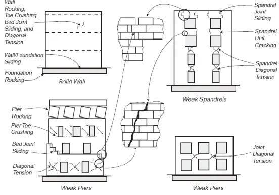
Figure 24 presents some of the common collapse mechanisms and damage associated to each element.
Figure 23 - In plane behavior of masonry walls. (Adapted from FEMA 306 (1998))
2.3
D
IAPHRAGMSThe floors and roof structure also play an important part on collecting and transmitting the inertia forces to the vertical structural systems. The capacity to distribute the horizontal seismic loads depends on the in plane stiffness of the diaphragms composing the floors. As said before, in URM the floors are flexible and the connections are not as adequate as they should be and as a consequence is not possible to redistribute the horizontal loads. The main advantage of the stiff diaphragm is to assume compatible horizontal displacements
in every point of each floor and therefore to allow the distribution of the seismic forces proportional to the stiffness of the resistant vertical elements. If the proportional distribution was applicable it would be possible to control the stresses distribution and avoid the failure of the façades. The effect of the floors in the behavior of the buildings when subjected to horizontal loads is presented in Figure 25.
Flexible diaphragms and inadequate tie-in connection between walls and floor can also provoke excessive displacement at the floor level and overturning of the perimeter out-plane walls. Retrofitting of ancient masonry buildings is often including the strengthening of the floors as a way to simultaneously decrease the out-of-plane displacements and increase the distribution of shear forces to the lateral resisting walls.
Figure 24 – Examples of wooden layout floors. (Brignola & Podestà, 2008)
To have in plane stiff diaphragms, yet badly connected to the walls, can generate undesirable collapse mechanisms as the expulsion of the corners and torsion mechanisms due to the differences between the position of the centre-of-mass and the centre-of-stiffness. As a consequence if the building has a layout which has the tendency to have torsional effects, probably it is not advised to increase the stiffness of the floors even if it decreases the tendency to out-of-plane failures (Brignola & Podestà, 2008).
Figure 25 – Behavior in functions of connections links between walls and type of floors.
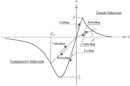
As suggested by Brignola & Podestà (2008), to consider the flexible floors its overall stiffness can be considered as a combination of the in plane stiffness of the diaphragm (keq,d) and the stiffness of the connections between floors and walls (kc). The total deformation of the floors is the sum of the deformations of the diaphragm and connections. As a consequence, if the connections are rigid (kc =∞) the overall deformation is only a function of
the internal stiffness of the diaphragm. However, if the diaphragms are rigid (keq,d =∞) the stiffness of the connections should be taken into account. The equivalent stiffness of the floors (keq,d+c), which should be used in the assessment, design and strengthening analyses, is given by the combination of both contributions (1/keq,d+c = 1/keq,d + 1/kc).
2.4 P
ERFORMED SEISMIC ANALYSISAnalysis on historic structures can be performed mainly in three types: linear analysis, non linear analysis and limit analysis. Linear analysis can be linear static analysis or modal dynamic analysis. Non linear analysis can be connected to the material, geometrical and contact non linearity. It is also possible to carry out non linear analyses with damage models. The limit analysis can be of static analysis and kinematic analysis which will lead to the determination of the collapse loads.
The linear analyses are the simplest and most widely used. The nonlinear analyses are closer to the reality however they are more complex. To perform a nonlinear static analysis it is common to use the pushover analysis, which consists in applying monotonic incremental loads to set up the capacity curve of the model and accounts for the nonlinear behavior of the structure. The non linear dynamic time history analysis is the most complex one and takes into account the variation of the properties of the model during the time and so it is necessary to define the nonlinear hysteretic behavior of materials and structure.
In the case of masonry structures and for strong accelerations, it is mandatory to perform a kinematic analysis, which can be a simplified one with the verification of the accelerations or non linear analysis considering the blocks rigid (the bodies will only rotate or displace). After analyzing the typology of the building, and based on the available abacus, it is necessary to select the possible mechanisms by means of kinematics models and based on equilibrium conditions which provide a collapse, calculate the coefficient C = a/g for the elementary mechanism, i.e. the seismic mass multiplier that leads the element to failure.
2.4.1 Static Linear Analysis
Before doing the non linear analysis a static linear analysis was performed. This type of analysis is the most easy and less complex analysis described in the codes. It is commonly used to model static loads that are permanently applied to the structure (e.g. self-weight, foundation settlement), normally leading to a pre-yield elastic response.
2.4.2 Dynamic Properties
The dynamic characterization of the structure is essential to know the response of the building and to obtain the vibration modes and natural frequencies of the model studied. The structure has a number of modes equal to the number of degrees of freedom and each degree of freedom correspond to one vibration mode and one
frequency value. Generally, in the case of reinforced concrete buildings, the first modes are more representative of the dynamic behavior, since they illustrate the mode shapes with high deformation and modal participation factor. Nevertheless, since ancient masonry buildings have deformable floors, some local modes can appear within the first mode shapes, so it is necessary to analyze carefully the deformed shape and their modal participation factor. The modal participation factor is obtained as the ratio between the modal excitation factor Eq.(1) and the modal mass Eq. (2), and it gives a measure of how strongly a given mode is participating in the dynamic response of the structure.
(1)
(2)
However, since mode shapes can be normalised in different ways, the absolute magnitude of the modal participation factor has in effect no meaning, and only its relative magnitude with respect to the other participating modes is of significance. The analysis of the effective modal mass as a measure of the importance of each of the structure's modes is even more useful, since it is possible to know the amount of mass, that is being excited by each mode . Modes with high values of effective modal mass are likely to contribute significantly to the response (Chopra, 1995). A number of modes should be presented until reaching a contribution of around 90% of the total mass in each direction.
In the case of masonry unreinforced buildings with flexible floors the torsional mode shape is not present like it happens in the case of reinforced concrete buildings. On the other hand the structure with flexible floors will present some modes shapes where the structure is not maintaining the original angles between the gable walls and the façades.
2.4.3 Non linear static analysis - Pushover
Analytical computations based on conventional force-based methods have indicate sometimes the total collapse of masonry structures, due to considerable seismic actions in situations where the actual behavior of the structures was only the partial collapse or even only some cracks. These relevant differences are being overcome by using more refined displacement-based approaches such as the pushover analysis. The application of pushover methods for the assessment of existing masonry buildings has been introduced into seismic codes and some of the most used methods are: N2 method presented in Eurocode 8, the method of ATC40 and the method presented on Fema 273/356.
In general, the pushover analysis presented on the codes is based on a simplified mechanical approach which considers the non linear behavior of structures by means of their capacity curve; the plot relating the increasing horizontal force distribution and the horizontal displacement can be obtained reducing the pushover analysis result through the definition of an equivalent SDOF system. The seismic demand is estimated in terms of
spectral displacement (performance point), intersecting the so called Capacity Spectrum (the Capacity Curve plotted in terms of spectral acceleration and displacement) with the earthquake response spectrum, plotted in AD format (acceleration vs. displacement) and properly reduced to take into account the effects of energy dissipation related to non linear structural response (Galasco, Lagomarsino, & Penna, 2006). The limit states are then defined with reference to the displacement capacity.
Normally, to perform static non linear analysis, two different distributions can be adopted (Galasco, Lagomarsino, & Penna, 2006):
Modal distribution – it is able to represent the structural dynamic amplification, which increases the action on higher storeys;
Uniform distribution – it is able to describe the behavior of a building under extensive damage, preventing force redistributions among levels.
These two distributions may be assumed as boundary conditions for seismic analyses since the actual result, coming from the non linear dynamic analyses, is assumed to be within these two solutions and the real failure mode is predicted by one of the two distributions (Galasco, Lagomarsino, & Penna, 2006).
The displacement control point, normally located on the top floor, is also highly influencing the results of the method; this difficulty is more evident in masonry buildings since there it is not possible to assume the master node as the story’s center of mass. In Galasco et al. (2006) it is studied the influence of the master nodes; for example, the results were more accurate when the master node was actually located on the weaker wall but the failure was achieve for the same maximum displacement for all the different nodes.
The N2 method proposed by Fajfar (2000) is a static non linear analysis with modal distribution of the loads and is one of the most used methods for seismic analysis of reinforced concrete buildings in Europe; if the N2 method is used, then the lateral loads applied are proportional to the first mode shape of the structure and the value of the horizontal forces in the i-the level, , is defined through the Eq. (3). Even the pattern of lateral loads to use is not clear, in a practical way; for example, in case of doubt, use both distributions and consider the envelope of the results.
(3)
Where,
– is the magnitude; – Story mass;
Φi – Displacement shape of the i-the mode.