Microcontroller based Controlled Irrigation System
for Plantation
1
S. R. Kumbhar, 2Arjun P. Ghatule
Abstract - The population of India has reached beyond 1.2 billion. If the population goes on increasing with the present rate then after 25-30 years there will be a serious problem of food, so in order to meet the demand of food one has to give more emphasis on the development of agriculture. Today, man has occupied all the suitable land but the land located far away from the human settlement is not developed properly and not utilized fully because it requires more manpower, time and expenditure. But now a days it is possible to pay more attention with the help of modern available controlled devices like computer, microprocessor, sensor, integrated circuits and microcontroller.
In the present work a Microcontroller based controlled remote irrigation system is developed for the agricultural plantation. The developed system is placed at the remote location and required water provides for plantation whenever the humidity of the soil goes below the set-point value. Humidity sensor provides proportional amount of output with change in humidity, which is compared, to the set-point and the data is taken through the channel. If the set-point data is high, then after motor is turned ON, which provides water to the plant till the humidity goes above set-point value. After reaching the humidity above set-point value motor is turned OFF and scans the next channel. This provides right amount of water at right time. The required software program is developed in assembly level language.
Keywords: Microcontroller based irrigation system, humidity sensor, remote operation, sensor based system, controlled irrigation.
I. INTRODUCTION
In India, most of the irrigation systems are operated manually. These traditional techniques are being is replaced with semi-automated and automated techniques [1-2]. Rajpal and Jain [3] suggested the automated concept of irrigation to use the water efficiently and effectively. Taking into account the ever growing requirement of the population, modern techniques are introduced to fulfill the demand of food. To increase the food production modern tools, fertilizers, irrigation facilities, multi-cropping pattern, insecticide, etc. are used. In order to give proper attention to the land located far away from the human settlement, supervisory automatic control systems like multi-terminal control systems are used [4], since in many processes, factors like soil, salinity, irrigation, temperature, light intensity, etc. needs repeated tasks and have to work in abnormal environmental conditions which lead to develop the microprocessor [5,7] as well as computerized control systems [8-10].
1. Department of Electronics and Head of Computer Sciences Department at Willingdon College, Sangli, (M.S.) India. (Contact No. +91 9923183867, [email protected])
2. Director, Sinhgad Institute of Computer Sciences (MCA), Pandharpur(M.S.) India. (Contact No. +91 8888842663, [email protected])
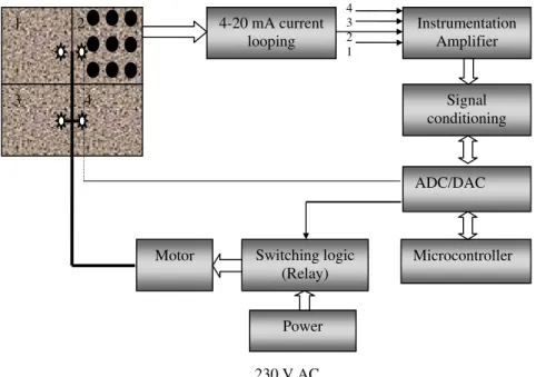
In the present work supervisory PIC microcontroller based irrigation system is developed for agricultural plantation. A piece of land is divided into four sectors. Humidity sensors are inserted just below the upper layer of the soil near each tree. The output of sensors varies according to the variation of percentage of humidity of soil. Minimum humidity output is set and the corresponding sensor output is compared through the comparator. Humidity sensor output goes below the set-point value then comparator is set to high, all the comparators outputs are connected to logic circuit. If any one of the input goes high, then OR gate provides high logic to 4-20 mA current loop. This output is coupled to the instrumentation amplifier which provides enough driving current to the one of the ADC channel.
A software program is developed in assembly language for reading the data through the channels. If the data is high then the controller set the motor to ON state by providing the signal to relay. The motor with outlet pipe is connected to each sector with separate valve. At the same time data is provided to the stepper motor to open the valve. This process continues as long as channel data is high. If channel data is low, it scans the next channel and the process repeats. This system helps to provide water for the plants whenever humidity goes below the set-point value.
II SYSTEM DEVELOPMENT
The present system is developed for irrigation of agricultural plantation which is divided into two parts. A) System hardware B) System software.
A. System hardware
Fig. 1 shows the block diagram of PIC Microcontroller based control irrigation system.
A..1 Sensors and comparators
Fig. 2 shows the arrangement of sensors and comparators in sector 2, with dots as planted trees with sensors. Humidity sensors are placed inside the soil near each tree. With decrease in humidity the sensor gives increasing output which is connected to the comparator whose value is set to some pre-determined set point.
When the humidity goes below the desired set-point value of the comparator is set at high output which is connected to the multiple OR logic circuit. Likewise outputs of all comparators are connected to the OR logic circuit. If any one of the comparator is set the output is high.
Proceedings of the International MultiConference of Engineers and Computer Scientists 2013 Vol II, IMECS 2013, March 13 - 15, 2013, Hong Kong
ISBN: 978-988-19252-6-8
ISSN: 2078-0958 (Print); ISSN: 2078-0966 (Online)
When the humidity goes below the desired set-point value of the comparator is set at high output which is connected to the multiple OR logic circuit. Likewise outputs of all comparators are connected to the OR logic circuit. If any one of the comparator is set the output is high.
A.2 Signal Conditioning Circuit and 4-20mA Current Loop
Received signal from the sensors is very small in magnitude. The amplitude of this signal is sufficiently increased through the instrumentation amplifier. This amplified signal is given to the 4-20mA current loop as the computer is far away from the sensor. The output of 4-20mA current loop is coupled to one of the channels of analog to digital card (ADC).
A.3 Sensor
The sensor used here is HIH 4030 which measures relative humidity [11] and produces linear analog output. It is designed at low power and draws 200 µA current with
enhanced accuracy and fast response time. Its output is stable and has low drift with very small size.
A.4 Relay Logic System
Two way 5V solid state relay is used in the present system. When the computer scans the high data through the input channel, it sends the high signal to relay to switch ON the 230V AC supply voltage and motor starts. The same controller also sends the appropriate channel data to stepper motor of the scanned sector to open the valve.
A.5 Interfacing Card
PCL series card 207 is used for ADC/ DAC signals required by the system. This Interfacing card is compatible and has low cost and the resolution is very high. Both ADC/ DAC conversion facility is available in the same card. It has eight single ended input ADC channels and two output DAC channels with very high resolution.
All the eight channels are independent and each requires 12-bit input data. Full scale output corresponding voltage generated can be selected for individual channels. 230 V AC
Fig. 3 Block diagram of interfacing card Fig. 2 Sensors and comparators arrangement
in the sector
4 3 2 1
Microcontroller ADC/DAC
Signal conditioning Instrumentation
Amplifier 4-20 mA current
looping
Switching logic (Relay) Motor
1 2
3 4
Power
Fig. 1 Block diagram of Microcontroller based irrigation system.
To switching circuit
Sensors in sector 2
ADC L
A T C H
DAC D
A T A B U F F E R
L A T C H
DATA M
icro
cont
ro
ller
D
A
TA
BU
S
Proceedings of the International MultiConference of Engineers and Computer Scientists 2013 Vol II, IMECS 2013, March 13 - 15, 2013, Hong Kong
ISBN: 978-988-19252-6-8
ISSN: 2078-0958 (Print); ISSN: 2078-0966 (Online)
Is Data = 1
Is Data = 1
Is Data = 1
Is Data = 1 Yes
Yes
Yes
Yes Is channel
=1
Is channel
=2
Is channel
=3
Is channel
=4
Yes
Yes
Yes
Yes No
No
No
No The hardware is specially designed to minimum
output settling time for each channel. Use of high performance OP-AMPS gives slew rate, which is greater than 10V/sec, which is good performance in present work. Fig. 3 shows the block diagram of the interfacing card.
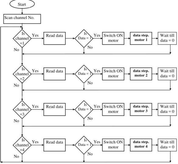
B. System software
System software for data reading and controlling the various devices is written in Assembly language. A simplified diagram of the software is shown in the Fig. 4. Executing the software program the channel is sequentially scanned. Scanning channel 1 data of corresponding channel is read, if it is high, it sends the high signal to the relay which switches the motor to 230 V supply. Motor becomes ON, at the same time Microcontroller sends data signal to the stepper motor 1 which opens the valve of sector number 1 and water starts flowing through the valve to the plants of sector. The process remains in the same state till the data of the same channel does not change, if the data is not high, then system scans the next channel and the process repeats as mentioned above for infinite time period.
III SYSTEM PERFORMANCE
The whole land is divided into 4 sectors, each according to the level of land and irrigation. Resistive humidity sensors are placed inside the soil near each tree. When the humidity (wetness) changes, the resistance changes and the output of sensor increase which is fed to the comparator and is set to some set point value of humidity. If the humidity sensor output exceeds the set-point value of comparator, it gives high output that means sector 1 needs water supply. All comparators outputs of sector 1 are connected to the multiple input OR gate. If any one of the comparator is set to high then it gives high signal to the amplifier.
The high output of OR gate is amplified by the instrumentation amplifier. The output of the instrumentation amplifier is given to 4-20mA current loop as host controller is far away from the sensor and sensor output quite low. In order to meet the current requirement driving the output device 4-20mA current loop is used. The sufficiently amplified output through instrumentation amplifier is connected to the ADC channel 1. Similar way outputs of
Scan channel No.
Read data
Read data
Read data
Read data
Switch ON motor
Switch ON motor
Switch ON motor
Switch ON motor
data step. motor 1
data step. motor 2
data step. motor 3
data step. motor 4
Wait till data = 0
Wait till data = 0
Wait till data = 0
Wait till data = 0 No
No
No
No Start
Fig. 4 Flow diagram of computer controlled irrigation system Proceedings of the International MultiConference of Engineers and Computer Scientists 2013 Vol II, IMECS 2013, March 13 - 15, 2013, Hong Kong
ISBN: 978-988-19252-6-8
ISSN: 2078-0958 (Print); ISSN: 2078-0966 (Online)
sector 2, 3 and 4 are connected to channels 2, 3 and 4 respectively. When the software program is written in assembly language and executed. It scans the channel sequentially. If any channel finds the high data then this high data signal is provided to switch ON the relay and motor whose outlet pipe is connected to valves of the different sectors. Opening and closing of the valve is controlled by the microcontroller through stepper motor. When channel is scanned then it activates the relay and motor gets start, at the same time data is provided to the respective sectors stepper motor which opens the valve. The motor remains ON till the input channel data doesn’t change. Else the motor remains OFF and valve is closed. After that it scans the next channel and process repeats for indefinite period. In order to save the power and energy as well as the use of the controller, the provision is made to keep controlled system OFF for certain time interval.
IV CONCLUSION
From the point of view of working at remote place the developed microcontroller based irrigation system can work constantly for indefinite time period, even in certain abnormal circumstances. If the plants get water at the proper time then it helps to increase the production from 25 to 30 %. This system can be used to irrigate very large areas as it only needs to divide the whole land into number of sectors and single microcontroller can control the whole process. It saves human energy, time, cost, etc. Not only the irrigation, the other factors like temperature, rainfall, wind, etc. can be checked continuously and accordingly the information is
supplied the user. It is also possible to correct the various parameters through the controller programming and one will get the required information at its need and necessary change in the action can be implemented in the software on the spot.
REFERENCES
[1] Fang Meir, D. D. Garrote, D. T. Mansion and S. H. Human, 1990, Automated irrigation system using plant and soil sensors, ASAE Publication 04-90 American Society of Agricultural Engineers St. Joseph, Michigan, pp 533-537.
[2] Clemens A. J. 1990, Feedback control system for surface irrigation management, ASAE Publication 04-90 American Society of Agricultural Engineers St. Joseph, Michigan, pp 555-560.
[3] A Rajpal, S. Jain, N. Khare, Proc. Of the ICSE 2011, RG Education Society, ISBN 978-981-7931-0 pp 94-96.
[4] S. R. Kumbhar, M. S. Gaikwad and M. D. Uplane, Multi-terminal Distributed Control System, Raman Memorial Conf., Nov. 1997, Pune. (India), pp 5.
[5] A. K. Mukhopadhyay, and N. C. Dass, Microprocessor based PHESS meter, IEEE Trans. Ind Appl. IE. 1987, pp. 78 - 82.
[6] H. Y. Zhong, H. P. Messinger, M. H. Rashid, A new microprocessor based direct torque control system for three-phase induction motor, IEEE Trans. Ind. Appl. 27, Mar / April., pp. 294 - 298.
[7] S. R. Kumbhar, simulation and on-line parameter estimation of DC motor using computer, M. Phil. dissertation, Shivaji University, Kolhapur, 1998. (India).
[8] S. Shanti Kumar, S. K. Biswas and J. Vithyathil, Microprocessor based field oriented control of a CIS-fed induction motor Drive, IEEE Trans. on Ind. Electronics, Vol. IE-33, pp. 39-43, Feb. 1986.
[9] R. Johnson, Moments of a new ac induction motor control system, In Provc. European Power Electron. Conf., Aachen, Germany, pp. 17 - 22, 1989.
[10] F. Williams and B. DeJagar, “ Modeling and control of rotating stall and surge: An overview,” ASME J. Turbo Machinery, Vol. 114, No. 2, pp 231-232, Apr. 1992.
[11] Data sheet of Humidity sensor HIH 4030 by Honeywell + Sparkfun Electronics.
Proceedings of the International MultiConference of Engineers and Computer Scientists 2013 Vol II, IMECS 2013, March 13 - 15, 2013, Hong Kong
ISBN: 978-988-19252-6-8
ISSN: 2078-0958 (Print); ISSN: 2078-0966 (Online)