Generation and Refinement from
Requirement Documents
Gustavo Cabral
1,2and Augusto Sampaio
21Mobile Devices R&D Motorola Industrial Ltda
Rod SP 340 - Km 128,7 A - 13820 000 Jaguariuna/SP - Brazil
2Centro de Inform´atica - CIn
Universidade Federal de Pernambuco - UFPE Caixa Postal 7851 - 50732-970 - Recife/PE - Brazil
{gflc,acas}@cin.ufpe.br
Abstract
The automatic generation of formal specifications from requirements suppresses the complexity of formal models manual creation and reveals the immediate ben-efits of its usage, such as the possibility to carry out re-finements, and property verification, which contributes to project cost reduction and quality improvement. This pa-per proposes a Controlled Natural Language (CNL), a subset of English, used to write use case specifications according to a template. From these use cases a com-plete strategy and tools enable the generation of process algebraic formal models in the CSP notation. We define templates that represent requirements at different levels of abstraction, capturing different views of the system be-havior. Moreover, a refinement notion is defined to con-nect the generated CSP models through an event mapping relation between abstract and concrete models. This no-tion is further applied to detail use case specificano-tions and to automate its execution.
Keywords: Use Case Specification, Controlled Nat-ural Language, Formal Specification Generation, Formal Models Refinement, CSP.
1. INTRODUCTION
The use of formal models, which are an abstract way to specify computer systems, is an industrial reality. Ini-tially, the benefits regarding the use of an abstract nota-tion, before starting the system implementanota-tion, are
re-lated to a better understanding of the problem. What has become increasingly evident is that the use of an abstract formal representation combined with techniques of model refinement can even promote the decrement of implemen-tation time. One of the possible applications is the auto-matic generation of source code from formal models [24]. The testing phase has also been positively impacted by the use of models concerning test case generation [7].
As the starting point for software development, re-quirements need to be specially considered to produce high quality documents to serve as input to the (formal) model construction; therefore no uncertainties should main concerning its contents. There is a variety of re-quirement specification methodologies, such as the one proposed in [21] that proposes a requirements elicitation process performed in six steps and an agenda for formal specification development from requirements. Neverthe-less, even if requirements are appropriately captured, it is still a hard task to build models and implementations that reflect them. Usually, the transition from requirements to an analysis or design model is a manual process, and therefore error-prone.
cost-effective so that real projects can take advantage of formal specification benefits, such as mechanically ana-lyzing a system to check for deadlock and livelock free-dom, among other useful properties.
Rather than building specifications in anad hocway, some approaches in the literature have explored the derivation of formal specifications from requirements. ECOLE [36] is a look-ahead editor for a controlled lan-guage called PENG (Processable English), which defines a mapping between English and First-Order Logic in or-der to verify requirements consistency. A similar initia-tive is the ACE (Attempto Controlled English) project [13] also involved with natural language processing for specification validation through logic analysis. The work reported in [22] establishes a mapping between English specifications and finite state machine models. In indus-try, companies, such as Boeing [44], use a controlled nat-ural language to write manuals and system specifications, improving document quality. There are also approaches that use natural language to specify system requirements and automatically generate formal specifications in an object-oriented notation [26].
Concerning the format to write requirements, use cases describe how entities (actors) cooperate by perform-ing actions in order to achieve a particular goal. Some consensus is admitted regarding the use case structure and writing method [6]; a use case is specified as a sequence of steps forming system usage scenarios, and natural lan-guage is used to describe the actions taken in a step. This format makes use cases suitable to a wide audience.
Therefore, we build on the results achieved in [4] and propose a strategy that automatically translates use cases, written in a Controlled Natural Language (CNL), into specifications in the CSP process algebra [34]. For ob-vious reasons, it is not possible to allow a full natural lan-guage as a source. We define a subset of English with a fixed grammar in order to allow an automatic and mech-anized translation into CSP. Because the context of this work is a research cooperation between CIn-UFPE and Motorola called CInBTCRD, the proposed CNL reflects this domain. The generated formal model is used in this project as an internal model to automatically generate test cases, both in Java (for automated ones) and in CNL (for manually executed).
Unlike the cited approaches, which focus on transla-tion at a single level, we consider use case views possibly reflecting different levels of abstraction of the application specification. This is illustrated in this paper through a user and a component view. We also explore a refinement relation between these views; the use of CSP is partic-ularly relevant in this context: its semantic models and refinement notions allow precisely capturing formal rela-tions between user and component views. The approach is entirely supported by tools. Aplug-into Microsoft Word
2003 [40] has been implemented to allow checking adher-ence of the use case specifications to the CNL grammar. Another tool has been developed to automate the transla-tion of use cases written in CNL into CSP; FDR [33], a CSP refinement checker, is used to check refinement be-tween user and component views.
The major contribution of this article, on top of the results achieved in [4], is a strategy for automated re-finement of views representing models at different levels of abstraction. A refinement between two views (for in-stance, user and component views) requires a mapping to express a relationship between the events of these views, since, in general, each view has its own alphabet. Here we show that such a mapping can be automatically con-structed from the use case templates, as well as a table re-lating CNL sentences provided by the use case designer. This frees the designer from operating directly with the CSP notation. As far as we are aware, this is an original approach to refinement. Furthermore, we explore several applications of our refinement strategy such as, for ex-ample, the consistence between implementation and use cases through the automatic execution of the use cases written in CNL. We also propose the definition of sub-views through event decomposition. Each event from a view is further detailed into concrete events enabling its execution; it is necessary to implement the interface be-tween the user and the system in order to automate the delivery of events to the target application. Section 6, de-voted to this new approach to refinement and its applica-tions, is entirely new. We have also further improved the presentation in [4] in several respects: the introduction to CSP, the use case templates, the formal approach to re-finement, the examples and related work are all addressed in more detail.
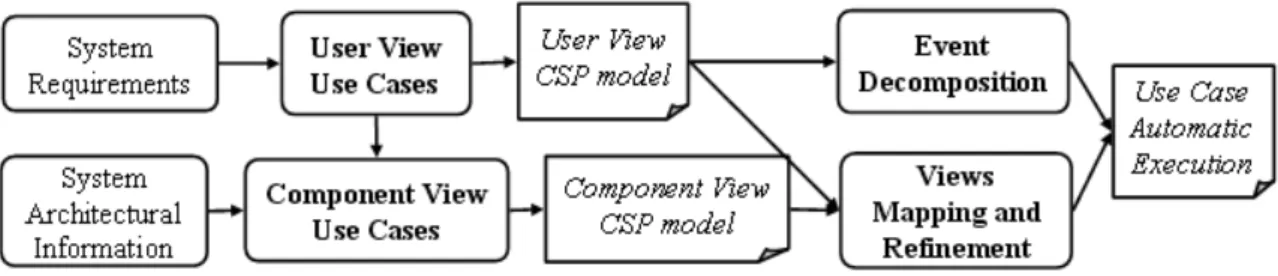
Figure 1. Proposed strategy overall process
2. STRATEGY
OVERVIEW
In our approach, the interaction between the user and the system, or between the system components, is docu-mented as use case specifications in a specified template. This template is structured to hold information concern-ing traceability with requirements, a brief description, and the way actors interact with the system. There are two use case templates: theuser viewand thecomponent view.
As shown in Figure 1, after System Requirements are described in an abstract way, defining what the system is intended to perform, user view use cases are created based on requirements analysis. This first set of use cases designs the ways actors interact with the system. Later, component view use casesare created based on the user view use cases and the adopted System Architectural Information, as presented in Figure 1.
The proposed approach focuses on use case specifica-tions because these are used as an input to other devel-opment phases such as design, coding, and testing. They constitute an essential part of the software development process. Therefore, we need to ensure that the visual depiction of the requirements is translated into clear and well-defined use case specifications [8].
As mentioned before, the language used to write these use cases is a Controlled Natural Language (CNL), a sub-set of English relevant for the specific domain. Using CNL it is possible to write imperative and declarative sen-tences. An imperative sentence describes actor actions and a declarative sentence depicts system characteristics, such as a GUI description or the current system state. CNL is necessary to restrict the vocabulary used to write use cases and its grammatical rules are defined by knowl-edge bases that map verbs to CSP channels and verb com-plements to values of CSP datatypes. Besides aiming at automatic generation of formal models, the use of CNL also prevents the introduction of ambiguous sentences in the use case specification, contributing to the quality of documentation.
Each use case sentence is translated into a CSP event, and a sequence of sentences produces a sequence of CSP events. These events are combined with the CSP prefix
operator giving rise to a CSP process. Each use case de-fines part of the system formal specification. The pres-ence of alternative or exception execution flows in use cases is captured by the CSP external choice operator, thus allowing process combination. Hence, theuser view use cases are translated into auser view use modeland thecomponent view use casesare translated into a com-ponent view use model.
Based on the generated models, a relation between user and component use cases is established by a mapping from the more abstract to the more concrete model (See Figure 1). This event mapping relation is used to prove that the component view model is a refinement of the user view model. This strategy not only enables the relation between these two views, but also allows the definition of multiple levels of abstraction within a view. The type of refinement that is explored here is called “event decom-position”. It enables the use case designer to detail events rewriting them as more concrete ones in order to ease the understanding of its behavior.
This decomposition can be carried out as many times as necessary; the goal is to translate every step into atomic steps enabling its implementation. Consequently, this al-lows the automatic execution of the use cases. The auto-matic execution aims to verify the adherence of the use case with the implemented system, validating the consis-tence between the operational use case behavior and the implementation. This automation strategy is application independent; any system can be validated once the pro-posed event dispatching interface is implemented. For Java applications this interface can be implemented us-ing the java.awt.Robot class or any available extension, such as that presented in [41]. The reflection mechnism, present in some programming languages, is also a possi-ble implementation alternative.
3. WRITING
CNL USE
CASES
for different purposes. In this section we present use case specification templates to document systems from the per-spective of the user and of the system components. Both templates define execution flows that determine the inter-action between the user and the system. The Controlled Natural Language (CNL), which can be seen as a process-able version of English, is used to write use case steps enabling validations and transformations.
3.1. USERVIEWUSECASE
User view use cases specify system behavior when one single user executes it. It specifies user operations and expected system responses. Table 1 presents a use case example. The following subsections explain what each use case field means and how it should be filled. The example itself is explained later.
3.1.1. Feature: Use cases are initially grouped to form a feature. Each feature contains an identification number. This grouping is convenient for organization pur-poses; it is not obligatory for the application of the pro-posed use case template. The use case itself includes a
related requirementlist, a briefdescription, andexecution flows.
3.1.2. Related requirement(s): The related require-ment list is used for traceability purposes, thus it is pos-sible to check the use case origin. This information is also used to group use cases by requirements. When re-quirements change, it is possible to know which use cases might be impacted and, if it is the case, update them. Test cases related to these use cases can also be updated or regenerated (assuming an automatic approach).
3.1.3. Description: The description field gives a gen-eral idea about the use case main purpose. Since each use case is related to some requirement, any clarification about this association is also described in this field.
3.1.4. Execution Flow: A use case specifies different scenarios, depending on user inputs and actions. Hence, each execution flow represents a possible path that the user can perform. The following subsections describe each part of an execution flow.
• Step
The tuple (user action, system state, system response)is called astep. Every step is identified through an identifier, anId. The user action describes an operation accomplished by the user; depending on the system nature it may be as simple as pressing some button or a more complex operation, such as printing a report. The system state
is a condition on the actual system configuration just before the user action is executed. Therefore, it can be a condition on the current application configura-tion (setup) or memory status. The system response is a description of the operation result after the user action occurs based on the current system state.
• Flow Types
Execution flows are categorized as main, alternative or exception flows. The main execution flows repre-sent the use caseshappy path, which is a sequence of steps where everything works as expected. An alter-native execution flow represents a choice situation; during the execution of a flow, such as the main flow, it may be possible to execute other actions, compris-ing choices. If an action from an alternative flow is executed, the system continues its execution behav-ing accordbehav-ing to the new path specification. Alter-native flows can also begin from a step of another alternative flow; this enables reuse of specification. The exception flows specify error scenarios caused by invalid input data or critical system states. Alter-native and exception flows are strictly related to the user choices and to thesystem stateconditions. The latter may cause the system to respond differently given the same user action.
• Reference between Execution Flows
There are situations when a user can choose between different paths. When this happens it is necessary to define one flow for each path. Every execution flow has one or more starting points, orinitial states, and onefinal state. The starting point is represented by theFrom stepsfield and the final state by theTo step field. The From steps field can assume more than one value, meaning that the flow is trig-geredfrom different source steps. When one of the
From stepsitems occurs, the first step from the specified execution flow is executed. TheTo step
field references only one step; after the last step from an execution flow is performed the control passes to the step defined in theTo stepfield.
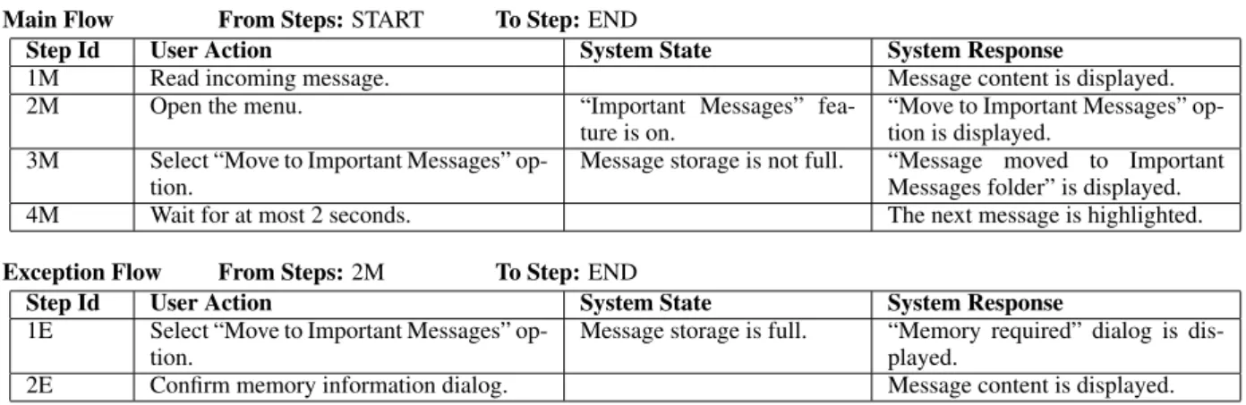
UC 02- Incoming message moved to the Important Messages folder
Related requirement(s):REQ 1302, REQ 1326
Description:User accepts an incoming message and moves it to the Important Messages folder.
Main Flow From Steps:START To Step:END
Step Id User Action System State System Response
1M Read incoming message. Message content is displayed.
2M Open the menu. “Important Messages” fea-ture is on.
“Move to Important Messages” op-tion is displayed.
3M Select “Move to Important Messages” op-tion.
Message storage is not full. “Message moved to Important Messages folder” is displayed. 4M Wait for at most 2 seconds. The next message is highlighted.
Exception Flow From Steps:2M To Step:END
Step Id User Action System State System Response 1E Select “Move to Important Messages”
op-tion.
Message storage is full. “Memory required” dialog is dis-played.
2E Confirm memory information dialog. Message content is displayed.
Table 1. Example of a user view use case
TheFrom stepsand theTo stepfields are es-sential to define the application navigation, which can be visualized as a Label Transition System [5]. These two fields also enable the reuse of existing flows when new use cases are defined; a new sce-nario may start from a preexistent step from some flow. Finally, loops can appear in the specification if direct or indirect circular references between flows is defined; this scenario can result in a livelock situ-ation in the case of infinite loops.
Some considerations: The user view use case in Ta-ble 1 is an example of a mobile phone functionality. Nev-ertheless, this template is generic enough to permit the specification of any application, not only mobile phone ones. The user view use case holds the main characteris-tics of other use case definitions, such as UML use cases [35]. However, our template seems to offer more flexibil-ity and standard. The existence of execution flows start-ing and endstart-ing accordstart-ing to other execution flows makes it possible to associate use cases in a more general way than through regular UML associations such as extend, generalization, andinclude. References enable the reuse of parts of other use cases execution flows and the pos-sibility of defining loops, so use cases can collaborate to express more complex functionalities.
3.1.5. Use Case Example: The example in Table 1 specifies a functionality presented in most mobile phones. This use case is written using the CNL, which is detailed in Section 3.3. It specifies that messages received by a mobile phone can be moved from the inbox folder to a special folder, called Important Messages folder. This user view use case, in particular, includes a list of
related requirements, a brief description, and two execu-tion flows: the main and the excepexecu-tion flow. TheFrom stepsfield, in the main flow, is defined as STARTso this flow does not depend on any other flow, and it is one of the possible starting points to navigate through this sys-tem. TheTo stepfield is set toENDso once the four steps from the main flow are executed the flow terminates successfully and the user can execute any use case with theFrom stepsfield set toSTART.
As already explained, the system state column is used to specify conditional situations. Note that this ex-ample captures only one exception flow. The normal execution of the main flow would pass through all its steps until step 4M, after which it successfully termi-nates (END). The exception execution, which describes the situation when themessage storage is full
(system state), starts from step 1E, just after the step
2M is performed. In this case, given the same user action, Select Move to Important Messages option, depending on the system state a different sys-tem response is presented. It was not defined an al-ternative flow for a possible Important Messages feature is offstate; if included, such a flow would start from step1M.
3.2. COMPONENTVIEWUSECASE
App,List App, andDisplay App; each one repre-sents different system concerns. For instance, the compo-nents Message Storage App and Display App
are responsible for saving messages at the message stor-age and displaying notices to the user, respectively. These components design the architectural level of abstraction, refining the user view use case specified in Table 1. In other words, for each user view use case a related compo-nent view use case is defined; user view steps are decom-posed into message exchange between components.
Normally, use cases describe system functionalities without revealing the internal structure of the system [35]. However, the proposed component view use cases break this convention and is actually used to detail user view use cases, which follows the regular use case idea, creating an interface between the actor and the system. The example in Table 2 is also written in the CNL; it is a refinement of the user view use case in Table 1. A formal strategy for proving this refinement is detailed in Section 5.
In the component view it is necessary to define the component that is invoking an action and the one that is providing the service. It is a message exchange process composed by a sender, a receiver and a message. The user is actually viewed here as a component, and can ei-ther send or receive messages to or from oei-ther compo-nents. A component can also send a message to itself. These particularities enable the definition of concurrent scenarios, which is a non-functional requirement. Thus, components can share resources and exchange messages, which is not possible in regular use case models [35].
Theexecution flowidea (main, alternative, and excep-tion) is the same as in the user view. The system state column plays the same role as previously described in the user view (see Section 3.1.4).
In Table 2, there is one main and one exception flow. The execution of the main flow can be deviated to an exception path after step7M, when theMessage App
sends a message to theMenu Controllercomponent. Here, the next message to be exchanged depends on the current system state. Just like in the user view exam-ple, theMessage Storagestate (full or not full) de-termines the next message to be exchanged between the components. Note that the exception flow step1Eis ac-tivated after the step 7M, when the condition fails. The
To stepfield, in the exception flow, states that after the execution flow finishes the execution of the use case ter-minates (END); it could alternatively transfer control back to the main flow.
3.3. CONTROLLEDNATURALLANGUAGE
As already mentioned, use case fields (user action, system state,system response, andmessage) are written in a Controlled Natural Language (CNL) with a grammar defined by knowledge bases. Using the CNL does not
only make use case text clear and uniform but also allows its processing in order to generate CSP constructions.
The CNL grammar is basically a subset of English. Its sentence constructions contain domain specific verbs, terms, and modifiers. The phrases construction is cen-tered on the verb. Domain terms and modifiers are com-bined to take thematic roles around the verb [10]. This strategy is detailed in [27] where it has been used to trans-late test case sentences into CSP constructions. The fol-lowing subsections describe the knowledge bases used to store these vocables involved in the definition of the CNL.
3.3.1. Lexicon: The Lexicon stores vocables that ap-pear in CNL sentences. Each vocable is averb, aterm, or amodifier. A verb is used to define an action or the system state. A term is an element, or entity, from the application domain. A modifier can be an adjective or an adverb that modifies a term. In the definition of each vocable, prop-erties are associated with each one of the verbs, terms and modifiers, allowing subject-verb and noun-modifier agreement checking. The meaning of modifiers, for in-stance, is to qualify terms; they have no particular role besides distinguishing terms.
Figure 2 gives examples of application domain term and modifier definitions. This example defines two terms:
message storage is full, referring to a dialog name, andmessage storage, referring to an applica-tion item that can be manipulated somehow. The modi-fiers areonlyandcorrectly. Their definitions con-tain thepositionandprecedencefields that deter-mine how they are positioned among terms or other mod-ifiers. Thenumber inflectiondefines whether it is asingularorpluralmodifier. Thearticlefield determines if the modifier accepts an article or not.
3.3.2. Ontology: Each application domain has spe-cific elements and entities represented as terms, which are grouped in classes according to their characteris-tics. These classes are related by inheritance. Figure 3 presents a small fragment of the Ontology that defines the
Object, theValue, and the State Valueclasses. TheState Valueclass inherits from theValueclass, and the Value class inherits from the Object class. Note that, in Figure 2, the term message storage is full is a dialog due to the fact that it belongs to thedialogclass of the Ontology.
Main Flow From Steps:START To Step:END
Step Id Sender Message System State Receiver
1M User Read incoming message. Message App
2M Message App Open incoming message. Message Viewer
3M User Open the Menu. Message App
4M Message App Display Menu. “Important Messages”
feature is on.
Menu Controller
5M Menu Controller “Move to Important Messages” option is displayed.
User
6M User Select the “Move to Important Messages” option.
Message App
7M Message App “Move to Important Messages” option. Menu Controller 8M Menu Controller Save message at “Important Messages”
folder.
Message storage is not full.
Message Storage App
9M Message Storage App
“Message moved to Important Messages folder” is displayed.
User
10M User Wait for at most 2 seconds. User
11M Message App The next inbox message is highlighted. List App
12M List App Available message is selected. User
Exception Flow From Steps:7M To Step:END
Step Id Sender Message System Response Receiver
1E Menu Controller Save message at “Important Message” folder.
Message storage is full. Message Storage App
2E Message Storage App
“Memory required” message is dis-played.
Display App
3E User Confirm memory information dialog. Message App
4E Message App Message content is displayed. User
Table 2. Example of a component view use case
sentence. When a sentence is constructed, each term, along with modifiers, takes a thematic role around the verb. Each case frame can also be associated to more than one verb, all of them assuming the same meaning. Fig-ure 4 is the definition of theSelectItemcase frame, which is defined by two verbsselectandchoose.
3.4. CASEFRAMERESTRICTION
The case frame restriction defines the relation between verb arguments and Ontology classes. Each verb argu-ment belongs to an Ontology class in order to restrict the way phrases are written. This minimizes the possibility of writing semantically incorrect sentences.
Figure 5 contains the case frame definitionSetItem
for the verbs set and check, and its respective case frame restriction. Observe that this case frame contains the following roles: agent, theme, and to-value. Based on these roles, there are four defined restrictions: the first three restrict thethemeand theto-value ar-guments, and the last one restricts only thetheme argu-ment; theto-valueargument is not mandatory. Each restriction has a name; this name is used to define a CSP datatype. Finally, it is necessary to associate every role to an Ontology class. This association restricts verb argu-ments, for example: theDTSET FIELDVALUE FIELD
restriction defines that the theme is a term from the
fieldclass and theto-valueargument belongs to the
field valueclass.
3.5. SOMECONSIDERATIONS
The definition of user view and component view use cases involves previous knowledge of the application re-quirements and architectural definitions, such as design patterns. Only after the designer is aware of these defini-tions and has decided which use cases are to be created, the use case writing should start.
During the creation of the two views, a relation be-tween requirements and use cases is defined. This rela-tion is detailed enough to point which use cases should be verified whenever requirements change. An alterna-tive approach would be mapping requirements to steps. This would enable verifying what steps are impacted if requirements happen to change. However, this last ap-proach revealed itself to be laborious and resulted in fre-quent references updates.
<noun>
<term>message storage</term> <plural/>
<model>MESSAGE_STORAGE</model> <class>item</class>
</noun> <noun>
<term>message storage is full</term> <plural/>
<model>MESSAGE_STORAGE_FULL</model> <class>dialog</class>
</noun>
<modifier>
<term>only</term>
<position>before</position> <precedence>0</precedence>
<numberinflection>singular</numberinflection> <article>no</article>
<model>ONLY</model> </modifier>
<modifier>
<term>correctly</term> <position>both</position> <precedence>1</precedence>
<numberinflection>plural</numberinflection> <article>no</article>
<model>CORRECTLY</model> </modifier>
Figure 2. Term and modifier definitions in the Lexicon
receiver component can respond this request through an-other message dispatch. This time the receiver acts as the sender, and vice-versa. UML sequence diagrams are also used by the Motorola development team; the automatic generation of these diagrams from a textual description represents an important benefit [9].
The adaptation of a diagrammatic language, such as UML 2.0 [38], to support features presented in the user and component views is a subject for future research. Pre-liminary investigation suggests that the user view use case can be modeled as a combination of the use case and the activity diagram of UML. Moreover, since the component view use case can be used to generate sequence diagrams [9], it is possible that they can actually be specified as an-notated sequence diagrams. However, in spite of UML being a visual language, its practical use depends on tools and the understanding of the UML standard. Yet, the proposed approach relies on textual descriptions, possi-bly supported by tools as described in the next section.
3.6. TOOLSUPPORT
Use case sentences must be adherent to the CNL grammar, so designers have to know the CNL gram-mar. There is a tool that automatically generates the CNL grammar documentation from the presented CNL knowl-edge bases. The CNL grammar is generated as HTML pages so it is possible to learn the CNL syntax navigating through the grammar definitions. In addition, if new
do-<class>
<description>Generic Class</description> <name>Object</name>
<code>object</code> <subclasses>
<class>
<description>Represents a generic value</description>
<name>Value</name> <code>value</code> <subclasses>
<class>
<description>Represents a state value, e.g.,"enabled","ON","high".</description> <name>State Value</name>
<code>state_value</code> <subclasses/>
</class> ...
Figure 3. Ontology fragment
main specific terms or expressions need to be added to the CNL, it is possible to regenerate the HTML documenta-tion. Even with this documentation, learning the CNL can be a complex task. Thus, it is recommended that the de-signer do not waste much time trying to figure out a way to write sentences adherent to the CNL. He should focus attention on the use case behavior.
Therefore, we have developed a tool to automatically validate the use case sentences and report all found in-consistencies. This tool is calledUse Case Validatorand it is a Microsoft Word 2003 [40]plug-in. It ensures use cases are written according to use case templates and the CNL syntax. MS Word 2003 is capable of structuring the use case contents through XML schema definitions. The plug-in processes the use case sentences to find inconsis-tencies (phrases not according to the CNL grammar). Two modules compose the plug-in. One is implemented using the .NET Platform [23] and the other is implemented in
<frame>
<description>Select an item from location. Example: Select the send message option from menu</description> <name>SelectItem</name>
<verblist>
<verb>select</verb> <verb>choose</verb> </verblist>
<roles>
<role mandatory="True">agent</role> <role mandatory="True">theme</role> <role mandatory="false">from-loc</role> </roles>
</frame>
<frame>
<description>Set the value of an item. Example: Set the Fix Dialing to on</description>
<name>SetItem</name> <verblist>
<verb>set</verb> <verb>check</verb> </verblist>
<roles>
<role mandatory="True">agent</role> <role mandatory="True">theme</role> <role mandatory="false">to-value</role> </roles>
</frame>
<frame>
<name>SetItem</name> <restrictions>
<restriction name="DTSET_FIELDVALUE_FIELD"> <class role="theme">field</class>
<class role="to-value">field_value</class> </restriction>
<restriction name="DTSET_SENDABLEITEM"> <class role="theme">sendable_item</class> <class role="to-value">state_value</class> </restriction>
<restriction name="DTSET_STATEVALUE_ITEM"> <class role="theme">item</class>
<class role="to-value">state_value</class> </restriction>
<restriction name="DTSET_ITEM"> <class role="theme">item</class> </restriction>
</restrictions> </frame>
Figure 5. Case frame and respective case frame restriction example
Java [19]. The .NET module is a GUI program that ac-complishes the CNL validation within Word. The Java module is the Natural Language Processing (NLP) unit responsible for verifying whether sentences are written according to the CNL rules. We have also implemented a Java version of theUse Case Validator. It reads a Mi-crosoft Word file and reports all inconsistencies, such as sentences not following the CNL grammar.
4. CSP SPECIFICATION
GENERATION
Once use cases are created and validated using the tool mentioned in the previous section, it is possible to auto-matically generate CSP formal specifications.
4.1. CSP NOTATION
The CSP process algebra [34] is the target formalism of our strategy because it can describe complex aspects of systems, such as concurrency, in an abstract notation but still very close to implementation. It allows the de-scription of systems in terms of processes that operate in-dependently (parallelly), and interact (communicate) with each other, and with the environment.
The relationship between processes is described using a few process algebraic operators that allow the definition of complex process compositions. The behavior of a CSP process itself is described in terms of sequence of events, which are atomic and instantaneous operations. Through a message-passing mechanism, named channels are in-troduced using thechannelkeyword. These channels can transmit messages; channels can also transmit data of a specified datatype. As an example, we present the datadoorand two channels: openandclose; the ex-ecution of the open!door event outputs the value door through the channelopen. Thecloseevent can be simi-larly used to close the door. There are also two primitive processes: STOPandSKIP.STOPcommunicates noth-ing and stands for a canonical deadlock;SKIPrepresents successful termination.
CSP Operators: Some of the CSP operators are pre-fix (a → P), deterministic or external choice (P✷Q), and nondeterministic or internal choice (P ⊓ Q). The prefix operator combines an event and a process to pro-duce a new process. The external choice operator allows the future behavior of a process to be defined as a choice between two component processes. The internal choice operator similarly allows the future evolution of a pro-cess to be defined as a choice between two component processes, but does not give the environment any control over which of the component processes is selected. For example,(a → P) ⊓ (b → Q)can behave like either
(a → P)or(b → Q); it refuses to accept (engage on) aor b, and it is only obliged to communicate (transmit) an event if the environment offers bothaandb. Nonde-terminism is also introduced into a deterministic choice if the initial events of both sides of the choice are identical. In(a → a → STOP)✷(a → b → STOP), it is not possible to determine the system state after the occurrence of the eventa.
channel a, b, c
events_view_1 = { a, b, c} View_1 = a -> ( b -> View_1
[] c -> View_1)
channel a1, a2, a3, b1, b2, c1
events_view_2 = {a1, a2, a3, b1, b2, c1} View_2 = a1 -> a2 -> a3 ->
( b1 -> b2 -> View_2 [] c1 -> View_2)
Figure 6. CSP process examples
tools, such as model checkers. CSPmis used to define all the CSP specifications in this paper. The channels (events)a,b, andcare used by and constitute the alpha-betofView 1, and the channelsa1,a2,a3,b1,b2, and
c1are thealphabetofView 2. Both processesView 1
andView 2use the prefix and the external choice oper-ators. For instance, after engaging on eventa,View 1
offersbandcto the environment. After engaging onb
orcit recurses. This example is purely symbolic, but it is useful to illustrate simple CSP processes and refinement notions, which are discussed in the next section.
Other CSP operators are hiding (P\s, wheresis the set of events to be hidden), renaming (P[[c←d]]), interleav-ing (P ||| Q), and the interface parallel or parallel com-position (P[| s|]Q, wheresis the set of events in which P andQ synchronize). The hiding operator provides a way to abstract processes by making some events unob-servable. A trivial example of hiding is(a →P)\ {a}; assuming that the eventadoes not appear inP, it reduces (simplifies) toP. The renaming operator replaces the oc-currences of channels by other channels in a process. For instance,P[[c← d]]is a process that behaves likeP ex-cept that all occurrences of channelcinPare replaced by channeld(so thatc‘becomes’d).
The interleaving operator represents completely in-dependent concurrent activity. On the other hand, the parallel composition operator represents concurrent ac-tivity that requires synchronization between the compo-nent processes; events in the interface set can only occur when all component processes are able to engage on that event. The parallel composition operator is also defined asP[p || q]Q, wherepandqare sets of events accepted by the processesPandQ, respectively. In other words,p andqdefine the interfaces ofPandQ. As an example, the process(a→P)[| {a} |](a→Q)can engage on eventa, and becomes the processP[| {a} |]Q, which requires that PandQmust both be able to perform eventabefore this event can occur. In(a→P)[| {a,b} |](b→Q), we have an example of deadlock sincea andbcannot be offered simultaneously.
CSP Refinement: The notion of refinement is a par-ticularly useful concept that establishes a relation between processes (components). It captures the fact that one com-ponent satisfies at least the same conditions as another. Then we may replace a more abstract component by a more concrete one, without degrading the properties of the system. In CSP, the refinement relations are defined in three ways, depending on the adoptedsemantic model. The traces refinement is based on the sequences of events which a process can perform (thetracesof the pro-cess). A processPis a traces refinement ofP(P⊑tQ), if all the possible sequences of communications thatPcan execute are also possible forQ; formally:
P⊑tQ≡traces[[Q]]⊆traces[[P]].
A failure is a pair(t,R), wheretis a trace of the pro-cess andRis a set of events the process refuses to per-form at that point. Thus, thefailuresrefinementP⊑f Q requires that the set of all failures ofQare included in the failures set ofP, which means
P⊑f Q≡failures[[Q]]⊆failures[[P]].
A process is deadlocked if it can refuse to execute every event; it is commonly introduced when parallel processes do not succeed in synchronizing on the same event.
Thefailures-divergencesrefinement adds the concept of divergences in the failures refinement. The divergences of a process is the set of traces after which the process may livelock. This concept enhances the analysis of pro-cesses; it enables the designer to prevent the occurrence of potential situations when visible events are never per-formed. The failures-divergences refinement betweenP andQis defines as
P⊑fdQ≡(failures[[Q]]⊆failures[[P]])∧
(divergences[[Q]]⊆divergences[[P]]).
4.2. CSP EVENTSGENERATION
Based on the presented CNL knowledge bases, we de-fine the CSP alphabet channel names and the datatypes of the model. The verbs determine CSP channel names. Each class from the Ontology defines a CSP datatype. The terms and modifiers from the Lexicon are related to classes from the Ontology and therefore define datatype values. Using these mappings and the case frame defini-tions, it is possible to translate each sentence from the use cases into CSP events.
Read incoming message.
read.DTREA_SENDABLEITEM.(INCOMING_MESSAGE,{})
Message storage is not full.
isstate.DTISS_ITEM_STATEVALUE. (MESSAGE_STORAGE,{}). (FULL_STATE_VALUE,{NOT})
Figure 7. CNL sentences and their translation to CSP events
Figure 7 presents sentences from steps 1M and
System =
UC_02_1M ; System [] ...
UC_02_1M =
-- Read incoming message.
( steps -> read.DTREA_SENDABLEITEM.(INCOMING_MESSAGE,{}) -> -- Message content is displayed.
expectedResults -> display.DTDIS_FIELDVALUE.(MESSAGE_CONTENT_FIELD_VALUE,{}) -> UC_02_2M)
UC_02_2M =
-- Open the CSM.
( steps -> open.DTOPE_MENU.(CSM_MENU_LIST,{}) -> -- "Important Message" feature is on.
conditions -> isstate.DTISL_LIST.(FEATURE,{IMPORTANT_MESSAGE_FOLDER}).(ON_VALUE) ->
-- "Move to Important Messages" option is displayed.
expectedResults -> isstate.DTISS_MENUITEM_STATEVALUE.
(MOVE_TO_IMPORTANT_MESSAGES_OPTION,{}).(DISPLAYED_VALUE,{}) -> UC_02_3M) [] UC_02_1E
UC_02_3M =
-- Select the "Move to Important Messages" option.
( steps -> select.DTSEL_MENUITEM.(MOVE_TO_IMPORTANT_MESSAGES_OPTION,{}) -> -- Message storage is not full.
conditions -> isstate.DTISS_ITEM_STATEVALUE.
(MESSAGE_STORAGE,{}).(FULL_STATE_VALUE,{NOT}) -> -- "Message moved to Important Message folder" is displayed. expectedResults -> isstate.DTISS_DIALOG_STATEVALUE.
(MESSAGE_MOVED_TO_IMPORTANT_MESSAGE_FOLDER,{}).(DISPLAYED_VALUE,{}) -> UC_02_4M)
UC_02_4M =
-- Wait for at most 2 seconds.
( steps -> wait.DTWAI_ITEM.(SECOND, {AT_MOST.2}) -> -- The next message is highlighted.
expectedResults -> isstate.DTISS_SENDABLEITEM_STATEVALUE. (MESSAGE,{NEXT}).(HIGHLIGHTED_VALUE,{}) -> SKIP)
Figure 8. Part of the generated CSP specification from the user view use case of Table 1
INCOMING MESSAGE datatype value, which is gener-ated from theDTREA SENDABLEITEMcase frame re-striction (see Section 3.4) of the verbread. The sen-tence Message storage is not full contains the verbto be, conjugated asishere, used to describe someMessage storagecharacteristic. The verbto beis mapped to the eventisstate. The subject and the predicate from this sentence determine the datatype val-ues MESSAGE STORAGE,FULL STATE VALUE, and
NOT, which are used by theisstateevent based on the
DTISS ITEM STATEVALUEcase frame restriction. However, mapping CNL sentences to CSP events is just the first step to create the CSP model. The specifi-cation generated depends on the use case template. The following sections explain the generation strategy for the user and the component view use cases.
4.3. USERVIEWMODEL
Each step of a use case execution flow is mapped to a CSP process. This process name is defined by the step Id combined with the use case Id, forming
a unique identifier among all use case steps. Its body contains control events (steps, conditions, and
expectedResults) that delimit the events generated from the user action, system state, and system response fields of the use case. As already explained, each exe-cution flow hasFrom stepsandTo stepfields that determine when the flow starts and ends. They may refer to the steps from other execution flows or to theSTART
andENDkeywords.
Figure 8 shows part of the generated CSP model for the use case specified in Table 1. It contains theSystem
process, which is themainprocess, and four other pro-cesses that refer to steps from the use case main flow. TheSystemprocess refer to the processUC 02 1Mand any other execution flow with theFrom steps contain-ing the STARTkeyword (See Section 3.1.4). The pro-cessUC 02 2Mis defined as a CSP external choice be-tween the rest of the main execution flow, the process
UC 02 3M, and the exception flow, theUC 02 1E pro-cess. The processUC 02 4Mis finalized with theSKIP
4.4. COMPONENTVIEWMODEL
The component view model is quite different from the user view one. The component channels contain infor-mation about the components involved in the message ex-change and their names are suffixed byComp, making the user and component view CSP alphabets different. The datatypes used in both views are the same, since both use cases refer to elements from the same domain.
SubSystem1 = USER_P
[User_Channels||Message_App_Channels] MESSAGE_APP_P
SubSystem1_events = union(User_Channels, Message_App_Channels) SubSystem2 = SubSystem1
[SubSystem1_events||Message_View_Channels] MESSAGE_VIEWER_P
Figure 9. Part of the component processes composition
In Figure 9, the top level process that represents the component view model is defined by the par-allel execution of system components, including the user. They are composed pairwise using the alphabet-ized parallel operator. Each component accepts a set of events for synchronization; User Channels and
Message App Channels are examples of alphabet sets used in the composition.
Each component has a main process that is defined by the external choice among the component possible be-haviors in each use case. Each use case gives rise to a subprocess for each component, defined by the messages exchanged between itself and other components. Each step is mapped into two CSP events, one for each compo-nent that takes part in the communication. Each step de-fines events for the message passed between the compo-nents and the system state. After the message itself, there is a CSP prefix to the next step that involves the compo-nent. Figure 10 shows part of theUSER Pprocess for one use case. Events readComp.USER.MESSAGE APP
and isstateComp.MENU CONTROLLER.USER are examples of the communication between the user and system components. Similarly to the user view, if there are alternative or exception flows, the external choice operator is used to capture the alternatives. In Fig-ure 10, the USER UC 02 process contains an exter-nal choice between the processesUSER UC 02 9Mand
USER UC 02 3Eto denote the exception flow.
4.5. SOMECONSIDERATIONS
The user view main process,System(see Figure 8), is defined as the CSP external choice among the steps of use case flows that have the From stepsfield set to
START. In contrast, the component view main process is defined as the parallel composition between system
com-ponents, including the user.
Our model generation strategy is similar to [2], which generates Message Sequence Charts (MSC) from Use Case Maps [3]. However, the component view template promotes better reuse of specifications, since it is possi-ble to reuse any sequence of steps. Like CSP, MSC offer notation to capture the concurrent aspects of the specified system. Nevertheless, CSP is a process algebra that en-ables the definition of channels and datatypes, along with flexible and elegant parallel operators. In addition, the CSP notation is supported by a refinement theory, refine-ment checkers, such as FDR [17], animators [28], and im-plementations, such as JCSP [43, 42] and OCCAM [16].
In the generated model, the CSP external choice op-erator is used to represent the user decision. The user clearly has the choice between executing a certain se-lected use case. However, the use of the CSP exter-nal choice operator in the alternative or exception flows seems to be a subjective issue. Because the execution of an alternative or exception flow is enabled by a combina-tion of factors (user actionandsystem state), the CSP internal choice operator can be considered to be used instead. For our particular application domain, how-ever, the presence of nondeterminism in the model is ir-relevant since only the traces model (See Section 4.1) is considered by Motorola during test case [31] and UML-RT sequence diagram [9] generation.
4.6. TOOLSUPPORT
A tool has been implemented to mechanize the trans-lation of the user and the component views use cases into CSP models. The tool reads user and component views use cases as Word 2003 document files, checks its content (invoking the tool presented in Section 3.6), and generates the user and the component models.
Here, the NLP module [27] is once again used to retrieve CSP events from the CNL sentences. The use model generation tool itself implements the strategy pre-sented in this chapter; it structures the CSP events, which are effectively generated by [27], into processes to define the system formal model.
5. MODEL
REFINEMENT
re-USER_P =
-- Scenario Case: Incoming message is moved to the Important Messages folder USER_UC_02
[] ...
USER_UC_02 =
-- Message: Read incoming message.
readComp.USER.MESSAGE_APP.DTREA_SENDABLEITEM.(INCOMING_MESSAGE,{}) -> -- Message: Open the CSM.
openComp.USER.MESSAGE_APP.DTOPE_MENU.(CSM_MENU_LIST,{}) -> -- Message: "Move to Important Messages" option is displayed. isstateComp.MENU_CONTROLLER.USER.DTISS_MENUITEM_STATEVALUE.
(MOVE_TO_IMPORTANT_MESSAGES_OPTION,{}).(DISPLAYED_VALUE,{}) -> -- Message: Select the "Move to Important Messages" option.
selectComp.USER.MESSAGE_APP.DTSEL_MENUITEM.(MOVE_TO_IMPORTANT_MESSAGES_OPTION,{}) -> (USER_UC_02_9M [] USER_UC_02_3E)
USER_UC_02_9M =
-- Message: "Message moved to Important Message folder" is displayed. isstateComp.MESSAGE_STORAGE_APP.USER.DTISS_DIALOG_STATEVALUE.
(MESSAGE_MOVED_TO_IMPORTANT_MESSAGE_FOLDER,{}}).(DISPLAYED_VALUE,{}) -> -- Message: Wait for at most 2 seconds.
waitComp.USER.USER.DTWAI_ITEM.(SECOND,{AT_MOST.2}) -> -- Message: The next inbox message is highlighted. isstateComp.USER.LIST_APP.DTISS_SENDABLEITEM_STATEVALUE.
(INBOX_MESSAGE,{NEXT}).(HIGHLIGHTED_VALUE,{})-> -- Message: Available message is selected.
isstateComp.LIST_APP.USER.DTISS_SENDABLEITEM_STATEVALUE.(MESSAGE,{}).(AVAILABLE_VALUE,{}) -> USER_P
Figure 10. User process exchanging messages with other components
placing abstract events with more concrete ones, formally keeping track of the relationship between the models.
In this paper we consider only two abstraction levels, user and component views. A generalization of this strat-egy for an arbitrary number of views is discussed in Sec-tion 6.1. Moreover, use case designers may define new use case templates and propose new ways to map events from use cases written at different levels of abstraction.
In general, the main goal of our approach is to decom-pose events using other events that represent concrete sys-tem behavior, in an incremental way. This would enrich the model with more details and eventually the events can be mapped into operational constructions, such as pro-gramming languages commands (typically method calls).
5.1. REFINEMENTMAPPING
We consider that the relation between user and com-ponent models is a mapping from sequences of user events to sequences of component events; to avoid nonde-terministic behavior, aone to onerelationship between se-quences of events from the two models is necessary. This mapping is used by a CSP process (See Figure 11) that re-ceives a set of pairs of sequences and yields a process that represents the mapping. In each pair, the first sequence represents events from the user view, and the second se-quence contains events from the component view.
Figure 11 exhibits the process that represents the map-ping used in the refinement; theMAPPING process re-ceives the mapping between the two views and through theTRIGGERfunction defines an indexed external choice among the processes generated by the makeProcess
auxiliary function. This last function receives one se-quence that is initiated with the events from the abstract model followed by events from the concrete model and recursively uses the prefix operator to create a process ter-minated with theSKIPprocess.
MAPPING(map) = TRIGGER(map); MAPPING(map)
TRIGGER(map) = [] p : map @
makeProcess(first(p)ˆsecond(p))
makeProcess(<>) = SKIP
makeProcess(<a>ˆas) = a -> makeProcess(as)
Figure 11. Mapping process
concrete model. The mapping process works as a trigger from one view to another; events executed in the abstract model force the execution of the related concrete events.
The processes View 1 and View 2 from Fig-ure 6 are simple examples of abstract and concrete models. The View 1 model is more abstract than
View 2, and the strategy can be used to replace ab-stract events fromView 1with more concrete ones, us-ing theMAPPINGprocess. Figure 12 presents the map-ping between the two models and defines the process
View 1 with mapping, which have the events from
View 1 hidden, resulting inView 1 mappedthat is refined by theView 2model.
map = {(<a>,<a1,a2,a3>),(<b>,<b1,b2>), (<c>,<c1>)}
View_1_with_mapping = View_1 [|events_view_1|] MAPPING(map)
View_1_mapped = View_1_with_mapping \events_view_1
View_1_mapped [FD= View_2
Figure 12. Mapping function usage example
The last line of Figure 12 captures the assertion that
View 1 mappedis refined byView 2in the failures-divergence model. This mapping strategy is based on a framework composition technique [30]. Here we focus on relating events from different models for refinement purpose, while the framework composition strategy aims to accomplish communication between frameworks pos-sibly with different alphabets.
5.2. COMPONENTVIEW AS AREFINEMENT OF THE
USERVIEW
The same mapping strategy presented in the previous section is used to relate user and component view models. In this case the component view model refines the user view through events mapping, even though it contains a more complex structure, such as parallel composition.
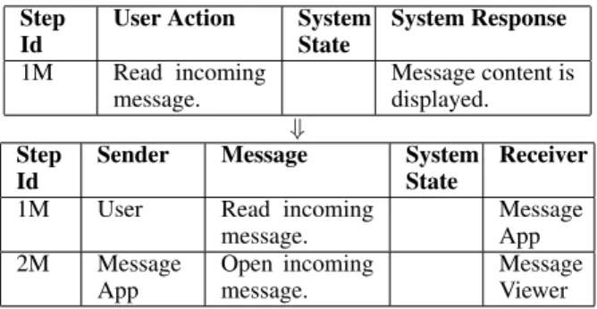
Figure 15 presents part of themappingbetween the user and the component view events. The event related to step1Mfrom the user view is mapped to the ones related to steps1Mand2Mfrom the component view, and the user view event from step2Mis mapped to the component view events of steps 3M, 4M, and 5M, establishing a relation between user and component views (Figure 13).
As explained, the component view refines the user view through events mapping. In some cases, it is also possible to retrieve the user view from the component view, provided an inverse mapping from the component to the user view.
User_View_with_mapping = User_View [| events_user_view |] MAPPING(map)
User_View_mapped = User_View_with_mapping \events_user_view
User_View_mapped [FD= Component_View
Figure 13. Mapping process specification based on the map
5.3. TOOLSUPPORT
The refinement relation discussed here can be me-chanically checked using FDR [33], a refinement checker for CSP. After loading the two models and the mapping functions, along with the generated mapping, the only re-maining task is to define assertions, such as in Figure 14, to check system properties. The first assertion is related to the illustrative example from Figure 12 and the second is related to the user and component view refinement from Figure 13. The results established that both refinements hold, as expected.
assert View_1_mapped [FD= View_2
assert User_View_mapped [FD= Component_View
Figure 14. Assert commands verified by the FDR tool
Also based on refinement checking, FDR can verify if a model is deadlock, livelock or nondeterminism free. Moreover, CSP operators bring the possibility to accom-plish quite complex compositions and FDR can be used to verify elaborate system properties.
The generation of the mapping that relates the user and the component views can be automated since a se-quence of events in the component view always starts with a user request and ends with a message received by the user. This information can be used to assist the event mapping task suggested in Section 6.
6. A STRATEGY FOR
AUTOMATED
RE-FINEMENT AND ITS
APPLICATIONS
map = { ( < steps, read.DTREA_SENDABLEITEM.(INCOMING_MESSAGE, {}),
expectedResults,display.DTDIS_FIELDVALUE.(MESSAGE_CONTENT_FIELD_VALUE,{})>,
< readComp.USER.MESSAGE_APP.DTREA_SENDABLEITEM.(INCOMING_MESSAGE, {}),
openComp.MESSAGE_APP.MESSAGE_VIEWER.DTOPE_SENDABLE_ITEM. (INCOMING_MESSAGE, {}) > ) ,
( < steps,open.DTOPE_MENU.(CSM_MENU_LIST, {}),
conditions,isstate.DTISL_LIST.(IMPORTANT_MESSAGES_FOLDER, {}), expectedResults,isstate.DTISS_MENUITEM_STATEVALUE.
(MOVE_TO_IMPORTANT_MESSAGES_OPTION, {}). (DISPLAYED_VALUE, {}) > ,
< openComp.USER.MESSAGE_APP.DTOPE_MENU.(CSM_MENU_LIST, {}),
displayComp.MESSAGE_APP.MENU_CONTROLLER.DTDIS_MENU.(CSM_MENU_LIST, {}), isstateComp.MESSAGE_APP.MENU_CONTROLLER.DTISS_FEATURE.(VALUE,{ON}), isstateComp.MENU_CONTROLLER.USER.DTISS_MENUITEM_STATEVALUE.
(MOVE_TO_IMPORTANT_MESSAGES_OPTION,{}).(DISPLAYED_VALUE,{}) > ), ... }
Figure 15. Mapping between abstract and concrete views
Concerning the proposed approach, in particular, it re-quires the direct manipulation of the CSP process algebra. Nevertheless, use case designers are not usually familiar or willing to work with formal notations. Our approach to automated refinement is to construct the relevant map-pings from information provided by the use case designer at the use case level; this information is described in terms of CNL phrases. The actual use of the CSP notation is hidden from the final user.
Considering the relationship between the user and the component views, formalized in the previous sec-tion, each step from the user view is selected and asso-ciated with one or more steps from the component view. This selection and mapping process is entirely accom-plished without the manipulation of CSP events; only CNL phrases are handled by the use case designer.
Step Id
User Action System State
System Response
1M Read incoming message.
Message content is displayed.
⇓
Step Id
Sender Message System State
Receiver
1M User Read incoming message.
Message App 2M Message
App
Open incoming message.
Message Viewer
Table 3. Example of event mapping from user to component view
As an example, Table 3 shows the step 1Mfrom the user view use case and its respective refinement, which are the steps1M and2M from the component view use case. Thus, once the user-component mapping is defined by the use case designer, manipulating CNL phrases only, we can generate the respective CSP events from these
phrases and use them to produce the mapping definition that is necessary for the refinement strategy presented in Section 5. The rest of this section presents possible ap-plications for the mapping between views, which can be automatically generated with the use case designer assis-tance and tool support.
6.1. EVENTDECOMPOSITION
An obvious application of event decomposition is re-lating sequences of events from different views as already discussed. However, this idea can be generalized.
Taking the user view as an example to apply the event decomposition strategy, note that it is possible to express the user behavior into several levels of abstraction. One simple phrase could actually define a complex action and therefore need to be decomposed in several simpler ac-tions. The classification of an action as complex or simple is related to the possibility of breaking it down in several sub-actions. This process would occur in an incremental way until the initial complex action is mapped to a se-quence of atomic actions (or events) that does not need to be further detailed. At this point, it is necessary to deter-mine the atomic events according to the interface between the user and the system. In other words, these are the con-crete events expected by the application.
Figure 16. Illustration of the event decomposition strategy
of events from a more abstract view is mapped to a se-quence of events from a more concrete view, just as in the refinement strategy presented in Section 5.
6.1.1. CNL Atomic Events: The definition of atomic events requires a close analysis of the system interface; all possible events accepted by the application should be listed. Once this set of atomic events is defined, it is nec-essary to add them, as verb definitions, to the CNL knowl-edge bases so they can be used by the CNL parser. The
pressoperation, for instance, defines an atomic event present in mobile phone applications; keys are pressed by the user to interact with the phone. Figure 17 defines thepressverb, case frame, and frame restriction. The
pressverb does not require a subject or an agent, it re-quires a theme that is the key to be pressed.
Thepressverb accepts verbal complements that are members of theDTPRESS PRESSABLEKEYclass from the Ontology. This class is composed by nouns represent-ing the possible keys that can be pressed by the phone user. Thus, CNL user actions can now be written as atomic events (concrete actions).
6.1.2. Decomposition Strategy: As presented in Sec-tion 3.6, the use cases are written using Microsoft Word and the CNL is validated by aplug-in. The use case is structured by an XML schema that annotates the docu-ment content enabling theplug-into access each part of the use case. The mapping presented in the beginning of this section (See Table 3) can be similarly defined us-ing XML annotations over the use cases. This strategy is used for arbitrary event mapping between views and, particularly, for event decomposition, mapping each user abstract action to a sequence of atomic concrete actions.
In Table 4, we have examples of user actions and
<verb>
<name>press</name>
<third-person>presses</third-person> <gerund>pressing</gerund>
<past>pressed</past>
<participle>pressed</participle> </verb>
<frame>
<description>Press a key. Ex.: Press the menu key</description> <name>pressKey</name>
<verblist>
<verb>press</verb> </verblist>
<roles>
<role mandatory="False">agent</role> <role mandatory="True">theme</role> </roles>
</frame>
<frame>
<name>PressKey</name> <restrictions>
<restriction name="DTPRESS_PRESSABLEKEY"> <class role="theme">pressable_item</class> </restriction>
</restrictions> </frame>
Figure 17. Definition ofpressverb, case frame and frame restriction
the respective atomic action. Since user definitions of events can be quite abstract, the decomposition of such events may occur in several stages. The actionSelect ‘Move to Important Messages’ option, for instance, is decomposed into the atomic actionPress down arrow key, which happens twice.
6.2. USECASEEXECUTION
User Action Atomic Actions
Read incoming message. Press center key. Confirm memory
infor-mation dialog.
Press left soft key.
Select “Move to Impor-tant Messages” option.
Press down arrow key. Press down arrow key.
Table 4. Decomposition of user events into atomic events.
may enable its execution. Once the set of atomic events is defined for a particular application domain, it is possi-ble to simulate the actual execution of its events. These atomic events are mapped to an interface that dispatches them to the system, simulating the user behavior.
channel press : DTPress
datatype DTPress = DTPRESS_PRESSABLEKEY. (KeyValue,Set(Modifier))
datatype KeyValue = MENU_KEY | CENTER_KEY | RIGHT_SOFT_KEY | LEFT_SOFT_KEY | ...
⇓
public interface AtomicEvents { public void press(KeyValue key); }
public enum KeyValue {
menu, center, rightSoft, leftSoft ... }
Table 5.Presschannel and associated datatype
Table 5 illustrates part of the CSP specification that defines thepresschannel and its associated datatypes; this definition is automatically derived from the CNL knowledge bases. Notice that the DTPress datatype holds theKeyValue information and a possible set of
Modifiers. Here, each CSP channel is mapped to a method in theAtomicEvents Java Interface and the datatypes are implemented as Java Enumeration. This Java code can be also automatically generated from the CNL knowledge bases.
6.2.1. Mobile Phone Automation: At this point, the automatic execution of an application depends only on the implementation of the presented interface. In the case of a Motorola mobile phone, there is an API that allows the access of the phone’s current state and event dispatching. Such an API enables the implementation of the presented interface. Thus, once a user view use case is written and each step is decomposed into atomic events, it is possible
to execute it, therefore verifying its consistence with the implementation. This procedure is seen as a preliminary development of the necessary infra-structure to enable use case or test case automatic execution.
In the case of test case execution, its generation from the user view CSP model (See Section 4) is achieved ap-plying strategies such as the one defined in [31]. This strategy allows the definition of test purposes (as CSP pro-cesses) that filter the generated model and yields traces according to specified guidelines.
6.2.2. Desktop Application Automation: Since the event decomposition strategy manipulates only CNL phrases in the use case specifications, it is extensible for different application domains, such as Desktop or Web applications. It defines a Platform Independent Model (PIM) [24]. It is a matter of updating the CNL knowl-edge bases with domain terms and define the set of atomic events (application interface) in order to enable the exe-cution of use cases (or test cases) in the new application domain. Thus, once the interface is implemented, it is possible to execute new use cases without extra effort.
This strategy was initially applied for Java Desktop applications since the Java platform implements an in-terface that provides access to the application’s running objects, such as Graphical User Interface (GUI) compo-nents. The java.awt.Robot class intercepts a running Java application and allows access to variable values and event dispatching, enabling the implementation of user actions. In the Desktop application domain, we have defined a new set of atomic events formed by theclickand the
typeevents. Table 6 contains part of these event def-initions. Theclickevent denotes the mouse click ac-tion performed on a specified item, such as a button or menu identified by a name (ClickValue). Thetype
action represents the interaction of the user through the keyboard, enabling data input.
The java.awt.Robot class can be directly used to ac-cess the running system. Nevertheless, more robust frameworks have been implemented to facilitate the ac-cess of the application GUI components. Jemmy [41] is a framework that provides a high level API to capture ap-plication state and perform actions. It is used in an ex-perimental implementation of the Java interface defined in Table 6 to validate the presented technique.
6.3. SOMECONSIDERATIONS
The event decomposition strategy presented in sub-section 6.1 is based on the formalism explained in early sections and enables the use of formal methods for the use case execution purposes. The strategy itself requires assistance from the use case designer, such as interface implementation, but the results seem promising.