768 Brazilian Journal of Physics, vol. 29, no. 4, December, 1999
Plasma Ion Implantation of Nitrogen into Silicon:
High Resolution X-ray Diraction
A. F. Beloto
1, E. Abramof
1,
M. Ueda
2, L. A. Berni
2, and G. F. Gomes
2;31: Laboratorio Associado de Sensores e Materiais, Instituto Nacional de Pesquisas Espaciais, C.P. 515 -12201-970 S~ao Jose dos Campos, SP, Brazil
2: Laboratorio Associado de Plasma, Instituto Nacional de Pesquisas Espaciais, C.P. 515 -12201-970 S~ao Jose dos Campos, SP, Brazil
3: FAENQUIL, Lorena, SP, Brasil
Received February 8, 1999
In the present study we use x-ray diraction methods to characterize the surface of Si wafers
irradiated with nitrogen by Plasma Immersion Ion Implantation. This is a non-line-of-sight ion implantation method, which allows three-dimensional treatment of materials including semiconduc-tors, metals and dielectrics. The atomic concentration proles in the implanted Si wafers were
measured by Auger electron spectroscopy. The (004) Sirocking curve (!-scan) was measured in
a high resolution x-ray diractometer equipped with aGe(220) four-crystal monochromator before
and after implantation. A distortion of the Si (004)-rocking curve was clearly observed for the
as-implanted sample. This rocking curve was successfully simulated by dynamical theory of x-ray diraction, assuming a Gaussian strain prole through the implanted region. The analysis made by x-ray diraction and Auger electron spectroscopy revealed successful implantation of ions with ac-cumulated nitrogen dose of 1:510
17cm,3. The
Siwafers can be used as high sensitivity monitors
in the Plasma Immersion Ion Implantation process, especially at the low dose range.
I Introduction
Plasma Immersion Ion Implantation (PIII) is a novel ion implantation technique developed recently for the improvement of the surface properties of materials in-cluding semiconductors, metals and dielectrics [1]. It is inherently a non-line-of-sight ion implantation method which allows three-dimensional surface treatment of manufactured workpieces of large dimension and/or complex shapes, at high speed, in batch processing mode and in a cost-eective manner [2]. In PIII, the ions of interest are extracted directly from the plasma in which the samples to be processed are immersed, without the need of acceleration grids.
In this work,Siwafers were implantedwith nitrogen
using the PIII technique. The wafers were character-ized by Auger Electron Spectroscopy (AES) in order to determine the concentration proles. The samples were analyzed by high-resolution x-ray diraction before and after implantation. The proles of the Si (004)
rock-ing curves were simulated by dynamical theory of x-ray
diraction and compared with the measured data.
II Plasma Immersion Ion
Im-plantation System
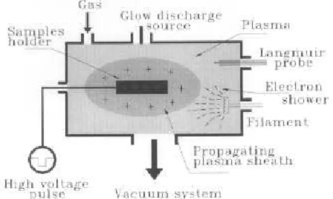
Fig. 1 shows a diagram of the PIII system used. The plasma is produced by a DC glow discharge source lo-cated inside a vacuum chamber (< 10
,3 mbar). The
three-dimensional ion implantation is achieved by ap-plying repetitively a negative high voltage pulse (7 to 15 kV, 5 to 10s duration times, 5 to 20 Hz repetition
A. F.Belotoetal 769
Figure 1. Schematic drawing of the DC glow discharge plasma ion immersion implantation system.
This system delivers plasmas with medium electron densities (n
e >10
10 cm,3) low electron temperatures
(T e
< 10 eV), controlled plasma potentials ( p)
be-tween 0 and 350 V, and with high stability for long op-eration times (> 50 h). The ion temperature is much
smaller than Te in such plasma. These characteris-tics allied with the possibility of low-pressure operation (< 10
,3 mbar) are highly favorable for the PIII
pro-cessing of materials.
III Nitrogen Implatation in
Sil-icon
We used 0.5-mm thick, 1.5 1.5 cm pieces of
p-type (100) Si wafer polished in one side and
chemi-cally cleaned just before their insertion into the vacuum chamber. They were xed and masked adequately in a metallic sample holder.
TheSi wafers were implanted with the plasma
po-tential controlled at
p= 70 V, with plasma density of
1:510
10cm,2. The high voltage pulser was operated
with peak voltage of 10 kV, 6s pulse duration and
rep-etition frequency of 20 Hz. Based on the sheath prop-agation model, an estimated dose of 1:010
17cm,2is
expected for 1500 min. of implantation
IV Auger Experiments
Measurements of the concentration proles of PIII ni-trogen implanted samples were performed by Auger Electron Spectroscopy. The AES result is depicted in Fig. 2 for a Si wafer implanted during 1500 min.. It
demonstrates the large concentration of nitrogen (60% a.c.) implanted into the Si lattice. The implanted
ni-trogen atoms reach depths down to 35 nm, which cor-respond roughly to the range of 10 keV,N
+ions in Si.
From this AES measurement, it is possible to conclude
that a retained nitrogen dose of about 1:510
17 cm,2
was reached.
Figure 2. Concentration proles of the nitrogen implanted
Si wafer (curve 1) measured with AES technique.
Con-centration proles of impurities present in the implanted sample are also shown.
The oxygen peak concentration of 50% observed in the AES spectrum in the rst 10 nm may have been formed by recoil implantation of oxygen from theSiO
2
native lm or from implantation of oxygen present as impurity in the discharge. This oxygen barrier is known to be crucial for a good retention of the implanted ni-trogen [4]. The tungsten peak (10% a.c.) observed near the surface comes from the heated tungsten lament.
V
High Resolution x-Ray
Diraction Analysis
The x-ray diraction measurements were carried out in a Philips X'Pert diractometer usingCuK
1
radia-tion. The incident optics is equipped with a four-crystal
Ge(220) monochromator which gives a horizontal
diver-gence of 12 arcsec and a wavelength dispersion of less than 310
,5. An open detector is used in the
sec-ondary optics. !-Scans around theSi(004) diraction
peak with the detector xed at the 2 Bragg angle (rocking curve) were performed on theSiwafers before
and after each implantation.
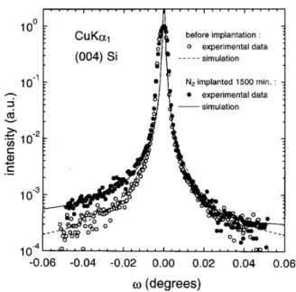
Fig. 3 shows the (004) diraction peak of aSiwafer
before and after 1500 min. of nitrogen implantation. An evident distortion of the rocking curve caused by the implanted nitrogen atoms can be observed in compari-son to the symmetrical rocking curve obtained for the same sample before implantation. Similar variations of x-ray (113) rocking curves inSiwafers implanted with
770 Brazilian Journal of Physics, vol. 29, no. 4, December, 1999
Figure 3. !-Scans around (004)Si diraction peak before
and after 1500 min. of nitrogen implantation. The solid and dashed lines are simulations by dynamical theory of x-ray diraction.
The (004) rocking curves were simulated by dynam-ical theory of x-ray diraction based on Takagi-Taupin equations [6, 7]. The implantation of ions in crystalline lattices creates strain in the implanted region. In our x-ray diraction simulation, the strain prole through the implanted region is supposed to be given by a Gaussian distribution. The central peak position (110 nm) and the width (140 nm) of the Gaussian strain distribution used in the simulation of the implanted diraction peak (solid line in Fig.3) were taken from the prole of ni-trogen atoms obtained from the AES spectrum shown in Fig. 2. The maximum of the strain distribution was 210
,3. No strain is assumed in the rocking curve
simulation of unimplantedSi (dashed line in Fig. .3).
Results from the x-ray diraction simulationshowed that the rocking curves are much more sensitive to the depth of the implantedregion than to the absolute value of the strain distribution An excellent agreement be-tween the simulated and measured (004) rocking curve was obtained for the implanted sample. This agree-ment demonstrates that the AES measureagree-ments corre-late very well with the x-ray diraction data.
VI Conclusion
Siwafers were implanted successfully with nitrogen in a
Plasma Ion Immersion Implantation system. They can
be used as retained dose monitors in the range from 1015 to 1017 cm,2, for low voltage PIII implantation
(10 kV), extending the results of a previous work car-ried out for higher voltage PIII (50 to 100 kV) [8].
The AES measurements showed that the implanted nitrogen region extended to a depth of 35 nm, which correspond roughly to the range of 10 keV,N
+ ions in Si.
The rocking curve of the Si (004) diraction peak
measured in a high-resolution x-ray diraction system showed an evident distortion after the nitrogen PIII process in relation to the same sample without implan-tation. The rocking curve of the implanted sample was simulated with success assuming a Gaussian strain dis-tribution in the implanted region taken from the AES nitrogen prole. The non-destructive x-ray diraction analysis performed in the implantedSiwafers give
use-ful information about the PIII process.
We gratefully thank Dr.R.Guenzel and Mrs. E.Quaritsch from Research Center Rossendorf, Dres-den, Germany, who made the AES measurement of our samples possible. G.F.Gomes is supported by CAPES fellowship.
References
1. J.R. Conrad, J.L. Radtke, R.A. Dodd, F.J. Worzala and N.C. Tran, J. Appl. Phys.,62, 4591
(1987).
2. D.J. Rej, inHandbook of Thin Film Process Tech-nology (IOP Publishing Ltd, 1996), pp. E2.3:1 -E2.3:25.
3. J.V. Mantese, I.G. Brown, N.C. Cheung and G.A. Collins, MRS Bulletin,21, 52 (1996).
4. S. Parascandola and O. Kruse, Annual Report 1997, Institute of Ion Beam Physics and Materials Research, Dresden, Germany, pp 40-43.
5. D.L. Chapek, J.R. Conrad, R.J. Matyl, S.B. Felch, J. Vac. Sci. Technol.,B 12, 951 (1994).
6. W.J. Bartels, J. Honstra, D.J.W. Lobeek, Acta Crystallogr. Sec., A42, 539 (1986).
7. A. Pesek, P. Kastler, K. Lischka, L. Palmetshofer, Nucl. Instrum. Meth. B 80, 569 (1993).