The limit of application of the Scherrer equation
M. A. R. Miranda* and J. M. Sasaki
Departamento de Fı´sica, Universidade Federal do Ceara´, Caixa Postal 6030, CEP 60440-970 Fortaleza, Ceara´, Brazil. *Correspondence e-mail: [email protected]
The Scherrer equation is a widely used tool to obtain crystallite size from polycrystalline samples. Its limit of applicability has been determined recently, using computer simulations, for a few structures and it was proposed that it is directly dependent on the linear absorption coefficient (0) and Bragg angle
(B). In this work, a systematic study of the Scherrer limit is presented, where it
is shown that it is equal to approximately 11.9% of the extinction length. It is also shown that absorption imposes a maximum value on it and that this maximum is directly proportional to sinB/0.
1. Introduction
The Scherrer equation is a widely used tool to obtain crys-tallite size (D) from X-ray powder diffraction measurements by describing a simple relationship betweenD, the full width at half-maximum () of the diffraction peak, the Bragg angle (B) and the wavelength of the radiation () (Scherrer, 1918;
Klug & Alexander, 1974; Langford & Wilson, 1978; Vives et al., 2004; Holzwarth & Gibson, 2011; Munizet al., 2016):
¼ K
DcosB; ð1Þ
where K is a parameter that depends on the relative orien-tation of the scattering vector to the external shape of the crystallite (Patterson, 1939; James, 1962; Langford & Wilson, 1978).
Equation (1) is based on principles similar to those of the kinematical (or geometrical) theory of X-ray diffraction, that is, after the incoming radiation is scattered by an atom it does not interact with the others. Furthermore, the derivation of equation (1) does not take into account the type or scattering power of the atoms, crystal symmetry or reflection used (Warren, 1969; Klug & Alexander, 1974). It is noteworthy that despite all these simplifications, it can provide acceptable results when compared with other techniques such as high-resolution transmission electron microscopy or small-angle X-ray scattering (Zhang et al., 2003; Shevchenkoet al., 2003; Borchertet al., 2005; Sherwood & Emmanuel, 2006; Weibelet al., 2005; Yinget al., 2009; Chahkandi & Mirzaei, 2017). These acceptable results are restricted to sizes up to a few hundreds of nanometres, and in fact Cullity & Stock (2001) argue that the Scherrer equation is valid only for crystallite sizes up to 200 nm. However, the limitation claimed by these authors is due to resolution of the diffractometers.
On the other hand, Munizet al.(2016) attributed the limit of applicability of the Scherrer equation to the physical assumptions made to obtain it, that are reasonable for imperfect and/or ‘small’ crystals (Zachariasen, 1945). For ‘large’ and perfect crystals, the waves scattered by one atom
ISSN 2053-2733
Received 16 August 2017 Accepted 14 October 2017
Edited by K. Tsuda, Tohoku University, Japan
Keywords:X-ray diffraction; Scherrer equation; dynamical theory; kinematical theory; Scherrer limit; crystallite size.
(or atomic plane) are also scattered by the other atoms (or atomic planes) and those waves are also subsequently scat-tered by other atoms and so on. This multiple scattering creates a wavefield inside the crystal and is properly dealt with by the dynamical theory of X-ray diffraction, which considers the dielectric constant of the crystal a three-dimensional and periodic complex quantity and uses Maxwell’s equations to describe the interactions of all beams (waves). This theory explains distinct phenomena that are not predicted by the kinematical theory, such as the Darwin width, primary extinction and the Borrmann effect (Darwin, 1914a,b; Zachariasen, 1945; Batterman & Cole, 1964; Pinsker, 1978; Authier & Malgrange, 1998; Authier, 2001). Munizet al.(2016) suggested that there is a limit of applicability of the Scherrer equation that is closely related to the limit between the dynamical and kinematical theories. They determined the Scherrer limit for three crystals, LaB6, Si and CeO2, and found
indications that it depends on Bragg angle and absorption. However, their findings are not general.
In this work we present a systematic study, using computer simulation, of the parameters that influence the Scherrer limit. First we use several crystals with similar structure and linear absorption coefficients,0, ranging from 595.9 to 2726.0 cm1. These crystals are arbitrarily chosen from the fifth row of the periodic table and the results show that the Scherrer limit does not depend only on0. Second, we create a prototype
struc-ture in which it is possible to vary each structural parameter independently. For this structure we show that the Scherrer limit increases with the scattering power (FH) of the reflection
[equation (6)] and Bragg angle. The effect of 0is to decrease
the Scherrer limit for FH<0:3. Third, we create a second
prototype structure to study the effect of symmetry and also to confirm the results of the first prototype structure. Further-more, it is shown that the Scherrer limit is independent of whether the structure is centrosymmetric or not. Finally, we obtained results independently of the structure by arbitrarily setting FH, FH, F0, V, B and , respectively, the structure factors of reflectionH,Hand 0, the volume of the unit cell, the Bragg angle and the wavelength of the X-rays. It was found that the Scherrer limit is approximately 11.9% of the extinc-tion length [equaextinc-tion (34)]. Furthermore, the effect of absorption is to impose a maximum value for the Scherrer limit that is directly proportional to sin=0.
2. Scherrer limit – calculation procedure
The rocking curves based on dynamical theory were calculated using the Zachariasen equation (Zachariasen, 1945) corrected by Wilkins (1978) and restricted to the Bragg symmetrical case and-polarized incident beam. The equation for this case is
IH=I0¼ j Hj2½
sin2ða0vÞ þsinh2ða0wÞ
=fjqþz2j þ ðjqþz2j þ jzj2Þ
sinh2ða0wÞ ðjqþz2j jzj2Þ
sin2ða0vÞ
þ1
2jðjqþz
2
j þ jzj2Þ2 jqj2j1=2sinhj2a0wj
þIm½zðqþz2Þ1=2sinð2a0vÞg; ð2Þ
in which I0 and IH are the intensities of the incident and
diffracted beam, respectively. The quantity zis given by the equationz¼ 0=2, in which 0is a function related to the
polarizability per unit volume in the forward direction, and is proportional to the deviation of the incident beam from the Bragg angle,¼2ðBÞsinð2BÞ. The variableqis defined
asq¼ H H where H¼ 4e2FH=m$2V,H¼ Hand
FH is the structure factor of reflection H. The m, e and$ symbols represent the mass, charge and angular frequency of the electron, respectively. Furthermore, V is the unit-cell volume, and v and ! are the real and imaginary parts of
ðqþz2Þ1=2, respectively.
The structure factor can be written as (Cullity, 1978)
FH¼PN
i¼1
ðfiþfi0þifi00Þexp½2iðhxiþkyiþlziÞ; ð3Þ
or
FH¼PN
i¼1
ðfiþf0
i þifi00ÞexpðiHxiÞ; ð4Þ
whereNis the number of atoms in the unit cell,fiis the atomic form factor of atomi, andf0
i andfi00are the real and imaginary
parts, respectively, of the correction to the atomic form factor due to resonance and absorption. The quantitiesxi,yi andzi are the fractional coordinates of the atoms in the unit cell and the position vector is given by x
i¼xia1þyia2þzia3, where
(a1, a2, a3) are the primitive vectors of the direct lattice. Figure 1
The set (h, k, l) represents the Miller indices and H = hb
1þkb2þlb3where (b1,b2,b3) are the primitive vectors of
the reciprocal lattice such that a
ibi¼2. In equations (3)
and (4) the effect of temperature is neglected.
The dependence of the rocking curves on crystallite size (D) is in the quantitya0¼k0D=sinB, in whichk0is the
wave-vector of the incident radiation andBis the Bragg angle.
The procedure to calculate the Scherrer limit is given by Munizet al.(2016). The first step is to obtain the rocking curve of a crystallite with sizeDDusing equation (2) (the subscript D
stands for dynamical theory). The second step is to measure the full width at half-maximum of the rocking curve and the third step is to calculate the crystallite size using the Scherrer equation (1), DS (the subscript S stands for Scherrer equation.). The ratioDS=DDis used to indicate how close the crystallite size obtained with the Scherrer equation is to the crystallite size used in the calculation with dynamical theory.
The three steps described above are repeated for several values of DD, ranging from a few nanometres to several
micrometres. Munizet al.(2016) defined the Scherrer limit as the value of DD for which DS=DD¼0:8. This limit is
reasonable from an experimental point of view, but in this work we intend to determine the point at which the Scherrer equation starts to lose validity. Therefore, the Scherrer limit is defined as the value of DD for which DS=DD¼0:95. Fig. 1
illustrates the calculation of the Scherrer limit for the (111), (110) and (111) reflections of the crystals of CeO2, LaB6and
Si, respectively.
It should be pointed out that this is a computer simulation study comparing two theories of X-ray diffraction, where no attempt is made to compare the results with experimental powder diffraction patterns. This procedure has the advantage of not having to deal with the contribution to the diffraction peak widths due to the individual characteristics of the instrumental apparatus.
3. Absorption and the Scherrer limit – crystals from the fifth row of the periodic table
The Scherrer limit for CeO2, LaB6and Si shown in the last
section was, respectively, 472.1, 876.6 and 1363.8 nm. Muniz et al. (2016) suggested that these values are inversely proportional to0, which for these crystals is
2117.3, 1091.6 and 143 cm1, respectively. This claim is
also supported by the fact that the quantity0Dis usually used to define the limit of application of the kinematic theory (Zachariasen, 1945), which can satisfactorily describe the diffraction peaks when0D1; therefore as0increases, this limit decreases.
To test Muniz’s hypothesis, the Scherrer limit was calculated for several crystals with different linear absorption coefficients. These crystals belong to space group Fm3m and have one type of atom per unit cell, where these atoms are from the fifth line of the periodic table, namely, Y, Zr, Mo, Tc, Ru, Rh, Pd, Ag, Sn, Sb and Xe. The range of0for this series of crystals calculated
using equation (5) (Authier, 2001) is from 595.9 to 2766 cm1:
0¼2RIm½F0=V; ð5Þ
where R¼2:8179401015m is the classical radius of the
electron (Mohr & Taylor, 2000) andF0is the structure factor
obtained by setting h¼0, k¼0 andl¼0 in equation (3). Table 1 lists0, the Scherrer limit and physical constants of
these crystals.
The Scherrer limit of the crystals of the fifth row of the periodic table is shown in Fig. 2. There is a general trend in which the Scherrer limit decreases as0increases. However, it is not possible to find a well behaved curve that describes the
Table 1
Scherrer limit and physical constants of the crystals from the fifth row of the periodic table.
The crystals belong to space groupFm3mand have only one type of atom per unit cell. The wavelength used was ¼1:54 A˚ and the reflection was (111). ICSD: Inorganic Crystal Structure Database.
Crystal
0
(cm1) Scherrerlimit (nm)
Lattice parameter
(A˚ ) F111 f0† f00† #ICSD
Y 595.9 232.2 4.97 126.1 0.2788 2.107 41510 Zr 862.1 191.3 4.51 126.4 0.1808 2.278 41511 Mo 1455.0 149.6 4.51 129.8 0.02557 2.743 41513 Tc 1748.8 138.4 3.9 131.6 0.01971 2.988 41514 Ru 2015.1 130.0 3.83 135.3 0.07269 3.261 41515 Rh 2726.0 113.8 3.591 136.1 0.1195 3.636 171677 Pd 2330.5 126.7 3.9 145.4 0.1739 3.982 41517 Ag 2169.8 133.4 4.0855 151.2 0.1754 4.262 52257 Sn 700.7 286.7 6.489 178.6 0.08831 5.515 40039 Sb 2005.7 154.4 4.61 167.7 0.01459 5.660 52198 Xe 1161.2 245.6 6.132 189.5 0.3546 7.712 43428
† The atomic form factors were calculated using the coefficients given by Waasmaier & Kirfel (1995) and the corrections due to resonance and absorption given by Cromer & Liberman (1970).
Figure 2
correlation of these two quantities. For example, if a straight line is passed through Y, Zr and Rh, it would not be easy to explain the values for Sn, Xe and Sb based solely on0. On the other hand, the crystals Ru and Sb have practically the same0but different Scherrer limits.
These results agree with the ones presented by Munizet al. (2016). To better understand the Scherrer limit it is necessary to make a systematic study, isolating the effect of each para-meter.
4. Prototype I
It was shown inx3 that0is not the only factor affecting the Scherrer limit, and that it is necessary to investigate other parameters such as the Bragg angle, structure factor and wavelength. To perform this study in a systematic manner a prototype crystal structure was devised, in which one para-meter can be varied while leaving the others unchanged. This crystal structure belongs to the space group Fm3mand has only one type of atom per unit cell. This choice of space group, besides being the same as for the crystals fromx3, is arbitrary and in principle does not interfere with the results.
The first parameter to be studied is FH, defined as the
scattering power of reflectionH:
FH¼ðjFHjjFHjÞ1=2=V; ð6Þ
whereFH was included because it is considered in the dyna-mical theory due to multiple scattering in the direction of the incident beam. On the other hand, FH should be inversely
proportional to V because one expects that denser crystals scatter X-rays more strongly. The parameterranges from 0 to 1 and is used to adjust the strength ofFH, which is needed to study its influence on the Scherrer limit.
To calculate FH, it is necessary to evaluate FH and FH using equation (3) or (4). The prototype I crystal has four equivalent positions, situated at (0, 0, 0), (0,1
2,12), (12, 0,12) and
(1 2,
1
2, 0). Therefore its structure factor is given by (Cullity,
1978)
FH¼ 0 for mixed even and oddh;kandl
4ðfþf0þif00Þ forh;k;lall odd or even:
ð7Þ
The effect of the Bragg angle on the Scherrer limit can be analysed by using different reflections. For example, for =
1.54 A˚ anda= 4.1 A˚ , the following reflections are accessible: (111), (002), (022), (113), (222), (004), (133), (024), (224) and (333); these cover a range of Bragg angles from 18.983 to 77.386.
The effect of absorption can be studied by varyingf00in the expression for0of prototype I:
0¼8Rf00=V: ð8Þ
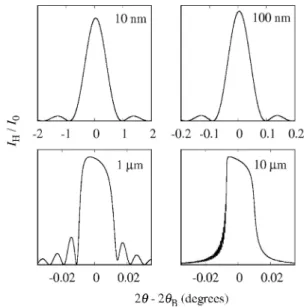
Table 2 shows the absorption values used in this work. The first step to obtain the Scherrer limit is to calculate the rocking curves using equation (2). The rocking curves obtained using prototype I parameters have the expected characteristics as the crystal size is increased (Fig. 3).
For DD¼10 and 100 nm the curves are symmetric, wide
and with side fringes of low intensity. These characteristics are the same as for peaks calculated using the kinematical theory. On the other hand, for DD¼1 and 10mm the peaks are
asymmetric and more intense for negative deviations of the Bragg angle, which are characteristics of peaks calculated using the dynamical theory. The next step is to repeat this calculation while changing systematicallyFH, 0 and B, to
study their influence on the Scherrer limit.
The variation of the Scherrer limit withFHcan be modelled
by an equation of the typey¼axm, which results in a straight
line in a log–log plot. Also, it increases withBwhile main-taining the same behaviour withFH (Fig 4).
For prototype I, the Scherrer limit is not affected by0for
FH 0:3. ForFH<0:30decreases the Scherrer limit and this reduction is greater for smallerFH(Fig. 4).
Values of0andf00used in this work for the calculation of the Scherrer
limit.
f00
0(cm1) ¼1.00 A˚ ¼1.54 A˚
0 0.0000 0.0000
400 1.2228 0.7940
600 1.8344 1.1912
1000 3.0573 1.9853
2000 6.1146 3.9705
3000 9.1718 5.9557
Figure 3
Rocking curves of the (111) reflection of prototype I and four values of DD. These curves shows the expected behaviour asDD increases. For DD¼10 and 100 nm they are wide and present low-intensity fringes on the sides while forDD¼1 and 10mm they are sharp and asymmetric because of dynamical effects. The maxima of the curves are 0.000803, 0.074188, 0.906999 and 0.937088 for 10 nm, 100 nm, 1mm and 10mm, respectively.FH¼FH¼146:493þi6:353,f
00¼1:9853 and
0¼ 1000 cm1
5. Prototype II
The results presented inx4 are not, in principle, general. The scattering power defined by equation (6) takes into account only the absolute values of FH and FH. There could be several reflectionsHandHof several different structures that give the same FH but where the structure-factor phases are
distinct.
To test these new configurations a new prototype crystal was devised. Prototype II belongs to space group F443 mand has two atom types per unit cell. The first type, calledA, are located at the fractional coordinates (0, 0, 0), (0,1
2, 1 2), (
1 2, 0,
1 2)
and (1 2,
1
2, 0). These are the same coordinates of the atoms as in
the prototype I crystal. The second type of atoms, calledB, are located at (1
4, 1 4,
1 4), (
3 4,
1 4,
1 4), (
1 4,
3 4,
3 4) and (
3 4,
3 4, 1
4) (Fig. 5).
The structure factor of prototype II is given by (Warren, 1969)
FH¼4
ðfAþif00
AÞ þ ðfBþifB00Þ forhþkþl¼4nðn2NÞ
ðfAþif00
AÞ ðfBþifB00Þ forhþkþl¼4nþ2ðn2NÞ
ðfAþif00
AÞ þiðfBþifB00Þ forhþkþl¼4nþ1ðn2NÞ
ðfAþif00
AÞ iðfBþifB00Þ forhþkþl¼4nþ3ðn2NÞ:
8
> > <
> > :
ð9Þ
Different forms of the structure factors can be achieved by selecting the ratiofB=A¼fB=fA. For example, the prototype I structure can be retrieved by setting fB=A¼0. Also, it is possible to change from a non-centrosymmetric (fB=A 6¼1) to a centrosymmetric structure (fB=A¼1).
For prototype I, the linear absorption coefficient is adjusted by changingf00; for prototype II there are two types of atoms and therefore0is given by
0¼8RðfA00þf
00
BÞ=V; ð10Þ
which means that several combinations off00
AandfB00can result
in the same absorption. In this work, their ratio was chosen to be the same ratio off.
The calculations show that the Scherrer limit does not depend on the configuration of the structure factor (fB=A). This means it is the same for centrosymmetric and non-centro-symmetric structures, even when06¼0 (Fig. 6)
6. General case:l0 = 0
In the last sections, the dependence of the Scherrer limit on reflecting power, Bragg angle and absorption was shown. However, those results are not general because they are based on a given structure. In this section, a different approach is used to study these dependencies; hereFH,FH,F0,V,Bare not calculated from a structure but, instead, are set arbitrarily. Although the parameters mentioned in the last paragraph are set arbitrarily, there are constraints that must be obeyed because they represent a real crystal structure. For example,
jFHj<jF0j, as one can see by inspecting equation (3). Therefore, it is important to use only those combinations of parameters that obey these constraints because these are the only sets that have a physical meaning. The determination of those constraints is easier if the crystal structures are divided
Figure 4
Top, variation of the Scherrer limit of prototype I withFH for several (hkl) reflections. It can be modelled by a function of the typey¼axm that gives a straight line in a log–log plot. For eachBthere is a set (a;m). Bottom, variation of the Scherrer limit of prototype I withFHfor several values of0. ForFH 0:3 the Scherrer limit is unaffected by0while for
FH<0:3 it decreases as0increases. This effect is larger for smallerFH. This result is for the (111) reflection and similar results were obtained for other reflections.
Figure 5
into four groups, depending on whether they are centrosym-metric or not and whether there is absorption or not.
6.1. Centrosymmetric crystal andl0= 0
The structure factor of a reflection H in a crystal with
0¼0 is given by
FH¼PN
j¼1
fj½cosðHxjÞ þisinðHxjÞ: ð11Þ
In a centrosymmetric crystal, for every atom in position x
there exists an equal atom in position x. Therefore, it is
possible to simplify equation (11) using the parity of the functions sine and cosine:
FH¼PN=2
j¼1
fj½cosðHx
jÞ þisinðHxjÞ
þNP=
2
j¼1
fj½cosðHx
jÞ þisinðHxjÞ; ð12Þ
FH ¼NP=
2
j¼1
fj½cosðHx
jÞ þisinðHxjÞ
þPN=
2
j¼1
fj½cosðHx
jÞ isinðHxjÞ; ð13Þ
FH¼2PN=
2
j¼1
fj½cosðHx
jÞ; ð14Þ
FH¼2A; ð15Þ
whereA¼PN=2
j¼1fjcosðHxjÞ.
For this category of crystals, the structure factor is a real number and consequently its phase angle,’H, is equal to 0 or . The next quantity to be determined is FH, which can be accomplished by substitutingHbyHin equation (14):
FH¼2NP
=2
j¼1
fj½cosðHx
jÞ; ð16Þ
FH¼2PN
=2
j¼1
fj½cosðHx
jÞ; ð17Þ
FH¼2A: ð18Þ
In summary, a centrosymmetric crystal with 0¼0 has the following constraints:jFHj ¼ jFHj and’H¼’H¼0. Table 3 shows the parameters used as input in equation (2) to study
their effect on the Scherrer limit; the calculations were performed for all the combinations of these parameters.
The Scherrer limit calculated with this general case approach is equal to the one calculated using prototypes I and II (Fig. 7).
A detail worth noting in Fig. 7 is the slightly different values ofV for the general case and prototype I: 68.921 A˚3 for the
former and 71.830 A˚3for the latter. Even though these values are different, the Scherrer limits are the same. This behaviour was confirmed when the calculations were performed for other values of V. Another parameter that does not affect the Scherrer limit isF0. On the other hand, the effects ofBand are the same as found for prototypes I and II (Fig. 8).
6.2. Non-centrosymmetric crystal andl0= 0
For a non-centrosymmetric crystal with 0¼0, equation (11) cannot be simplified as in the last section; therefore it
Figure 6
The Scherrer limit does not depend on the structure-factor configuration (fB=A) of prototype II when0¼0. It is equal to the Scherrer limit of prototype I (fB=A¼0) and also is not affected by the presence (fB=A¼1) or lack (fB=A6¼0) of a centre of symmetry. This result is for the (111) reflection and similar results were obtained for other reflections. Top,
0¼0. Bottom,06¼0. Input parameters for equation (2) (Zachariasen, 1945) to study their
effect on the Scherrer limit.
Parameter Values Units
Wavelength () 0.7, 1.0, 1.54, 2.0 and 2.5 A˚ Bragg angle (B) 15.186, 30, 45, 60, 75 and 85
Unit-cell volume (V) 71.830, 200, 350 A˚3
Re[F0] 300
Im[F0] 0
has to be analysed in its original form. Defining A0 = PN
j¼1fjcosðHxjÞ, B0 =
PN
j¼1fjsinðHxjÞ and ’H =
arctanðB0=A0Þit is possible to rewrite equation (11) as
FH¼A0þiB0; ð19Þ
FH¼ jFHjexpði’HÞ; ð20Þ
wherejFHj ¼ ðA20þB20Þ 1=2
.
The expression forFHis found by substitutingHforH:
FH¼PN
j¼1
fj½cosðHx
jÞ þisinðHxjÞ; ð21Þ
FH¼PN
j¼1
fj½cosðHx
jÞ isinðHxjÞ; ð22Þ
FH¼A0iB0; ð23Þ
FH¼ jFHjexpði’HÞ: ð24Þ
In summary, (a)jFHj ¼ jFHj; (b)’H¼ ’H.
Differently from the last section,’His not restricted to 0 or . However, it does not influence the Scherrer limit (Fig. 9). The effect of the other parameters is the same as observed in the last section. The set of parameters used in the calculations is shown in Table 4.
Figure 8
The Scherrer limit does not depend on V and F0, and has the same variation withBandfound for prototypes I and II. These results were obtained using the general case approach with0¼0 and a centrosym-metric structure. In this example, when the following parameters are not being varied their values are: V¼71:830 A˚3
,F0¼300,B¼15 and ¼1:54 A˚ .
Figure 9
The Scherrer limit is independent of the structure-factor phase (’H). This same result is obtained for several combinations of the parametersF0,,
B and V. The calculations were performed using the general case approach for non-centrosymmetric structures and0¼0.
Table 4
Parameter set used to study the Scherrer limit in the general case approach.
The structure is centrosymmetric and0¼0.
Parameter Values Units
Wavelength () 0.7, 1.0, 1.54, 2.0 and 2.5 A˚ Bragg angle (B) 15.186, 30, 45, 60, 75 and 85
Unit-cell volume (V) 71.830 A˚3
Re[F0] 300
Im[F0] 0
jFHjminimum–maximum 3–240
Structure-factor angle (’H) 0, 10, 25, 45, 90, 135, 180
Figure 7
The Scherrer limits calculated using the general case approach and using the prototype I structure are equal. This confirms that the results obtained for prototype I are indeed general. This calculation was done for
In xx6.1 and 6.2 the variation of the Scherrer limit with several variables was studied; in this section a mathematical equation to quantify this dependence will be derived. The Scherrer-limit variation with FH can be represented by the following equation:
SðxÞ ¼ax; ð25Þ
where S is the Scherrer limit, x¼ FH, and aand are the fitting parameters.
It was shown that the Scherrer limit also varies withB, but retains the same behaviour as described by equation (25),i.e. in a log–log plot it is a straight line. It is possible to include this variation with B in the fitting parameters a and, so that
there is a set (a,) for eachB.
Equation (25) can satisfactorily fit the calculated Scherrer-limit variation withFH andB (Fig. 10). The variation of
withBis negligible, less than 2.5% (Table 5). From this point ¼1. The variation of a with B can be satisfactorily described by
a¼psinBþq ð26Þ
wherepandqare the fitting parameters. The line of best fit was obtained forp= 857.03215.280 nm2andq=3.9
11.9 nm2(Fig. 10).
The results presented above are for= 1.54 A˚ , and to find a general equation the procedure described before was repeated for several wavelengths. It was found thatqfluctuates around 0 and therefore can be considered constant,q¼0 (Table 6). The variation ofpcan be satisfactorily described by
p¼r ð27Þ
where rand are the fitting parameters. The line of best fit was obtained forr= 1323.87 nm1and ¼1:0 (Fig. 10).
The dependence ofSwithB,andFHcan be simplified by
combining equations (25), (26) and (27),
SðxÞ ¼rsinB
1
FH
; ð28Þ
in whichris given in nm1,in A˚ andF Hin A˚
3. Changing to
SI units and applying Bragg’s law:
SðxÞ ¼1:32387 1 2d
V
ðFHFHÞ 1=2 10
14: ð29Þ
Equation (29) is very similar to the equation for the extinction length given by Authier & Malgrange (1998):
0¼
RC
ð0jHjÞ1=2
V
ðFHFHÞ1=2; ð30Þ
in whichC = 1 ( polarization) orC = cosð2BÞ(
polar-ization). The definitions of 0 and H are shown in Fig. 11 and for the symmetric Bragg case 0¼cos’0¼sinB and
Figure 10
Left, fit of equationS ¼axto the calculated Scherrer-limit variation withF
H for several values ofB. The dependence onBis included in the parametersaand. The variation ofwithBis negligible and it can be set equal to 1. The Scherrer limit was calculated using the general case approach with0¼0. Middle, fit of equationa¼psinBþqto the variation ofawith singiven in Table 5. The line of best fit was obtained forp= 857.032
15.280 nm2
andq=3.911.9 nm2
. Right, fit of equationp¼r to the data in Table 6. The best values arer= 1323.87 nm1
and ¼1:0. Values of parametersaandobtained by fittingSto calculated values of the Scherrer limit for severalB.
() a Error Error
15.186 230.916 3.920 1.00337 0.004579 30.000 419.856 2.353 1.02146 0.001508 45.000 573.511 8.586 1.02877 0.004024 60.000 734.314 2.273 1.01855 0.0008332 75.000 827.880 2.668 1.01486 0.0008678 85.000 859.365 3.898 1.01268 0.001222
Table 6
Values of the parameterspandqobtained by fittinga¼psinBþqto the data in Table 5.
(A˚ ) p(nm2) Error q(nm2) Error
H¼cos’H¼ sinB. Substituting these values in equation (30) and usingpolarization one can write
0¼
R
sinB
V
ðFHFHÞ1=2; ð31Þ
0¼
R
1 2d
V
ðFHFHÞ
1=2: ð32Þ
Combining equations (32) and (29):
SðxÞ ¼1:3238710140R
; ð33Þ
SðxÞ ¼0:1190: ð34Þ
Equation (34) summarizes the dependence ofSwith all crystal properties and experimental details. It expresses the relation
that if the crystal is larger than 12% of the extinction length then the Scherrer equation starts to lose validity. This result agrees with those presented by Authier & Malgrange (1998) when studying the limit of validity of the kinematical theory. One of the effects predicted by the dynamical theory is the primary extinction, which is the decrease in intensity of the incident beam as it penetrates the crystal, because of destructive interference with multiple scattered beams in its direction; this decreases its depth of penetration. The Scherrer equation, or the kinematical theory, does not consider loss of intensity as the incident beam travels through the crystal; therefore the result that the Scherrer limit is directly propor-tional to the extinction length is reasonable.
7. General case:l0 6¼0
7.1. Centrosymmetric crystal andl06¼0
The structure factor of a reflectionHwhen06¼0 is given by
FH¼PN
j¼1
ðfjþif00
jÞ½cosðHxjÞ þisinðHxjÞ; ð35Þ
in which fj00 is the imaginary part of the correction of the atomic form factor due to absorption. The real part of the correction is included infj.
Following the procedure shown in x6.1, it is possible to simplify equation (35) by using the fact that for each atom in a positionxthere exists an equal atom in the positionx:
FH¼P
N=2
j¼1
ðfjþif00
jÞf½cosðHxjÞ þisinðHxjÞ
þ ½cosðHx
jÞ þisinðHxjÞg; ð36Þ Figure 11
Definition of the direction cosines in the Bragg symmetrical case. The wavevectors of the incident and diffracted waves are denoted byk
0and kH, respectively, andnis the normal to the crystal surface.
Figure 12
Effect of’Hon the Scherrer limit. Left: the values of the Scherrer limit calculated for different’Hcoincide whenever equation (44) is satisfied, meaning that it is independent of’H. Right: example of the rocking curves obtained for the value of0indicated by the arrow in the left panel. For the parameter set used in this example, the maximum allowed value of’His 9.4. For’H= 0and 5the rocking curves are identical and have the expected shape. For
FH¼PN=
2
j¼1
ðfjþif00
jÞf½cosðHxjÞ þisinðHxjÞ
þ ½cosðHx
jÞ isinðHxjÞg; ð37Þ
FH¼NP=2
j¼1
ðfjþif00
jÞ½2 cosðHxjÞ; ð38Þ
FH¼2Aþi2C; ð39Þ
FH¼ jFHjexpði’HÞ; ð40Þ
in which C¼2PN=2 j¼1f
00
j cosðHxjÞ;jFHj ¼2ðA2þC2Þ 1=2
and tan’H¼C=A.
The structure factor of the reflectionHcan be obtained by
substitutingHbyHin equation (38):
FH¼NP=
2
j¼1
ðfjþif00
jÞ½2 cosðHxjÞ; ð41Þ
FH¼2Aþi2C; ð42Þ
FH¼ jFHjexpði’HÞ: ð43Þ
Equations (40) and (43) show thatjFHj ¼ jFHjand’H¼’H. Note that, differently from the case without absorption,’His not restricted to 0 or. Nevertheless, it has a restricted range because the imaginary part of the structure factor is limited by the value of the absorption. In mathematical terms
CP
N=2
j¼1
fj00: ð44Þ
The right side of equation (44) is equal to half the imaginary part of the structure factor of H¼0; therefore Im½FH Im½F0. Values of ’H set outside this allowed range do not have physical meaning because they do not represent real
structures. This can be seen on the rocking curves that present anomalous characteristics such as the appearance of double peaks (Fig. 12).
The Scherrer limit was calculated for several values of’H and the results are shown in Fig. 12. For ’H = 0 and 5 equation (44) is satisfied in the entire range of0. In this case, the Scherrer limit is independent of’H.
Once the possible values of ’H were determined, the Scherrer limit was calculated as a function of
0for several
values of0=sin. Fig. 13 shows that absorption decreases the Scherrer limit for high values of
0. The lines that go through
the points in the figure are from calculations using a different combination of (,) which yields the same0=sin. Several other combinations of parameters from the list presented in Table 7 were also tested.
The decrease in the Scherrer limit due to absorption is expected because it decreases the penetration depth of the incident beam, thus creating an apparent size. This effect is more pronounced for higher values of0(Fig. 13), where the influence of primary extinction is smaller. On the other hand, for smaller values of0, primary extinction is dominant and the effect of absorption is almost negligible.
7.2. Non-centrosymmetric crystal andl06¼0
For a non-centrosymmetric crystal with0, equation (35)
cannot be simplified as in the last section; therefore it has to be analysed in its original form, which can be rewritten as
FH¼FH0 þFH00; ð45Þ
where the contributions fromfandf00are separated:
FH0 PN
j¼1
fj½cosðHx
jÞ þisinðHxjÞ; ð46Þ
FH0 ¼ jF
0
Hjexpði’
0
HÞ; ð47Þ
and
FH00 PN
j¼1
ifj00½cosðHx
jÞ þisinðHxjÞ; ð48Þ
FH00 ¼ jF
00
Hjexpði’
00
HÞ: ð49Þ
The equation forFHcan be obtained by substitutingHforH
in equations (46) and (48):
Figure 13
Scherrer limit of the general case as a function of
0for several values of
0=sin. The lines represent the same calculations but with a different set (, B). For example, for 0=sinB¼11591 cm1
the points were calculated using ¼1:54 A˚ and B¼15 while the line was using
¼1:00 A˚ andB¼9:675.
Parameter set used to study the effect of
0 and 0=sinB on the Scherrer limit in the general case approach.
Parameter Value Units
0 0, 400, 600, 1000, 2000, 3000 cm 1
1.0, 1.54 A˚
B 9.675, 11.537, 14.478, 15.000, 17.939,
19.471, 22.644, 30.000, 30.866, 36.682, 50.354, 74.259
V 71.830 A˚3
jF0j 300
FH0 ¼ jFH0jexpði’0HÞ; ð50Þ
FH00 ¼ jFH00jexp½ið’
00
HÞ: ð51Þ
Besides equations (50) and (51), the other restriction in the structure-factor value isjF00
Hj<
PN
j¼1fj00orjFH00j<Im½F0.
The angle of the structure phase, ’H, does not have the restriction found for the centrosymmetric case. However, it does not change the Scherrer limit (Fig. 14). Calculations using several combinations of,B,F0,0andVproduced the same results found for the centrosymmetric case, meaning that the Scherrer limit depends only on0and0=sin.
7.3. Scherrer limit equation –l06¼0
A simple relationship between the Scherrer limit and
0
was found for structures with 0¼0 [see equation (34)].
Including absorption, it was found that it decreases the Scherrer limit for high values of 0 to the point where it creates a maximum value, which depends only on0=sin.
This dependence can be satisfactorily described by
Smax¼S0ðsin=0Þ
; ð52Þ
whereS0¼1:067107and¼0:980 (Fig. 15).
8. Conclusions
In this work we presented a systematic study of the limit of applicability of the Scherrer equation, the Scherrer limit, and showed that it is approximately 11.9% of the extinction length. This result agrees with the results presented by Authier & Malgrange (1998) when studying the limit of validity of the kinematical theory. Furthermore, we showed that absorption decreases the Scherrer limit for large extinction lengths and also imposes on it a maximum value.
References
Authier, A. (2001).Dynamical Theory of X-ray Diffraction, Vol. 11, International Union of Crystallography Monographs on Crystal-lography. IUCr/Oxford University Press.
Authier, A. & Malgrange, C. (1998).Acta Cryst.A54, 806–819. Batterman, B. W. & Cole, H. (1964).Rev. Mod. Phys.36, 681–717. Borchert, H., Shevchenko, E. V., Robert, A., Mekis, I., Kornowski, A.,
Gru¨bel, G. & Weller, H. (2005).Langmuir,21, 1931–1936. Chahkandi, M. & Mirzaei, M. (2017).J. Iran. Chem. Soc.14, 567–
575.
Cromer, D. T. & Liberman, D. (1970).J. Chem. Phys.53, 1891–1898. Cullity, B. D. (1978).Elements of X-ray Diffraction, 2nd ed. Reading,
UK: Addison-Wesley Publishing Co.
Cullity, B. D. & Stock, S. R. (2001).Elements of X-ray Diffraction, 3rd ed. New York: Prentice Hall.
Darwin, C. G. (1914a).Philos. Mag. Ser. 6,27, 315–333.
Darwin, C. G. (1914b).Philos. Mag. Ser. 6,27, 675–690.
Holzwarth, U. & Gibson, N. (2011).Nat. Nanotech.6, 534.
James, R. W. (1962). The Optical Principles of the Diffraction of X-rays: the Crystalline State Series, edited by Lawrence Bragg. London: G. Bell and Sons Ltd.
Klug, P. & Alexander, L. E. (1974).X-ray Diffraction Procedures for Polycrystalline and Amorphous Materials, 2nd ed., p. 687. New York: John Wiley and Sons.
Langford, J. I. & Wilson, A. J. C. (1978).J. Appl. Cryst.11, 102–113. Mohr, P. J. & Taylor, B. N. (2000).Rev. Mod. Phys.72, 351–495. Muniz, F. T. L., Miranda, M. A. R., Morilla dos Santos, C. & Sasaki,
J. M. (2016).Acta Cryst.A72, 385–390. Patterson, A. L. (1939).Phys. Rev.56, 978–982.
Pinsker, Z. G. (1978). Dynamical Scattering of X-rays in Crystals. Berlin: Springer-Verlag.
Scherrer, P. (1918).Nachr. Ges. Wiss. Go¨ttingen,1918, 98–100.
Sherwood, D. & Emmanuel, B. (2006).Cryst. Growth Des.6, 1415–
1419.
Shevchenko, E. V., Talapin, D. V., Schnablegger, H., Kornowski, A., Festin, O., Svedlindh, P., Haase, M. & Weller, H. (2003).J. Am. Chem. Soc.125, 9090–9101.
Vives, S., Gaffet, E. & Meunier, C. (2004).Mater. Sci. Eng. A,366, 229–238.
Figure 15
Fit of equationSmax¼S0ðsin=0Þ
(solid line) to the maximum Scherrer limit (open circles) calculated using the general case approach (double logarithm plot). The line of best fit was obtained forS0¼1:067107and
¼0:980. Figure 14
The Scherrer limit is independent of the structure-factor phase (’H). These calculations were done using the general case approach for non-centrosymmetric structures and 06¼0. The symbols ’0
Warren, B. E. (1969).X-ray Diffraction. New York: Addison-Wesley Publishing Co.
Weibel, A., Bouchet, R., Boulch, F. & Knauth, P. (2005).Chem. Mater.
17, 2378–2385.
Wilkins, S. W. (1978).Acta Cryst.A34, 343–344.
401–410.
Zachariasen, W. H. (1945).Theory of X-ray Diffraction of Crystals. New York: Dover Publications.
Zhang, Z., Zhou, F. & Lavernia, E. J. (2003).Metall. Mater. Trans. A,