Characterization of a Quarter Torus Filter for
Vacuum Arc Ion Flux Transmission
H. Kelly
∗, A. M´arquez
∗, and M. Pirrera
Instituto de F´ısica del Plasma (CONICET), Departamento de F´ısica,
Facultad de Ciencias Exactas y Naturales (UBA)
Ciudad Universitaria Pab. I, (1428) Buenos Aires, Argentina
Received on 19 December, 2003; revised version received on 30 April, 2004
Measurements on the ion flux transmission in a magnetically filtered d-c vacuum arc are presented. The device includes a metallic plasma-generating chamber with water-cooled electrodes coupled to a substrate chamber through a quarter-torus magnetic filter. It is employed a Copper cathode (6 cm in diameter) with a Copper annular anode. The filter consists in a steel cylinder 500 mm length and 100 mm inner diameter with90oof bending angle and corrugated lateral walls, surrounded by a magnetic field generating coil. The arc is operated at a current level of100A, and the intensity of the filtering magnetic field was in the range0
−200G (measured
at the knee of the filter). This magnetic field is enough high so as to magnetize the electrons but not the ions. The discharge is ignited by bringing (and later removing) a tungsten striker into contact with the cathode. The arc voltage drop, the floating potentials of the filter and the plasma, and the ion current collected by probes located at different positions as functions of the magnetic field intensity are reported and compared with measurements presented in the literature with other similar devices.
1
Introduction
The cathodic vacuum arc is widely used to produce coatings[1]. The deposited material comes from highly ioni-zed plasma ejected from minute sizes on the cathode surface, known as cathode spots. The kinetic energies of the ions are in the range15−120eV, depending on the cathode mate-rial and on the charge-state of the ion[2, 3], and with a total ion current amounting to 8−10 % of the total discharge current[4].
The presence of microdroplets of melted cathode mate-rial in the coatings is a disadvantage in vacuum arc tech-nology, since for some applications this macrodroplets in-crease the porosity and roughness of the coating. Several attempts have been made to separate the metallic plasma from the microdroplets by means of different filtering sys-tems. The most popular of these systems are based on a fo-cusing magnetic field that magnetize the electrons and guide the metallic plasma through the filter to the substrate but le-ave unchanged the microdroplet flux [5]. Unfortunately, part of the plasma flux is lost in the filter; so many efforts have been devoted to the optimization of filters that is removing all the microdroplets with the minimum losses of plasma. Straight [6, 7, 8] and curved[5, 9, 10] filters have been stu-died. Presently, the one most often employed in practice is the so-called “quarter torus filter” (developed by Aksenov). It consists in a circular non-magnetic metallic tube with a bending angle of90o, and with a toroidal magnetic field ge-nerated by an external coil. The magnetic field intensity is in the range50−500G, a value enough high to magnetize
the plasma electrons. One of the most important findings in a quarter torus filter optimization consisted in applying a positive bias voltage (with respect to the plasma potential) of about10−20V to the filter.
In this work we present the first measurements perfor-med with a magnetically filtered arc at INFIP (DCF2 de-vice). The arc voltage drop and the floating potential of the filter as functions of the magnetic field intensity are repor-ted. By employing also ion collectors, measurements of the ion flux transmission and plasma floating potential for diffe-rent biasing voltages of the filter are reported and discussed.
2
Experimental setup
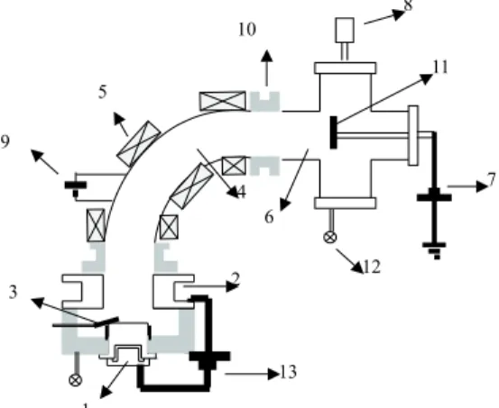
The investigations were carried out in a d-c filtered vacuum arc system, which is shown schematically in Fig. 1. There is a plasma generation chamber that includes a water-cooled copper cylindrical cathode (60mm in diameter) surrounded by a floating shield, an annular water-cooler cooper anode (80mm in diameter), and a tungsten striker which is brought into contact with the cathode surface and later removed to trigger the discharge. Both electrodes are mounted on an insulating piece that set an electrode separation of about15 mm. The anode was grounded. At the exit of this cham-ber is connected a magnetic quarter torus filter (500 mm length,100mm inner diameter) made of corrugated stain-less steel, including an external coil which produces the fil-tering magnetic field. The bending angle of the torus is90◦.
At the exit of the torus a deposition stainless steel vacuum chamber (cross shaped) is connected. The electrodes sys-tem, magnetic filter and deposition chamber are electrically isolated among them. By employing an independent d-c power source, the magnetic filter can be biased with respect to the anode. Two vacuum systems (composed of mecha-nical and diffusion pumps) pump separately the plasma ge-neration and deposition chambers to a base pressure of less than10−4
mbar. The discharge circuit consisted in a cur-rent supply (18kW,150A) in parallel with a capacitor bank (165mF) connected to the electrodes through a series induc-tor (2.8mH) in order to provide arc stability. The arc was operated in a continuous mode with an arc current of100A.
1
2 3
4 5
6
7 8
9
10
11
12
13
Figure 1. Scheme of the DCF2 device. (1) cathode; (2) anode; (3) trigger; (4) quarter torus magnetic filter; (5) torus coil; (6) deposi-tion chamber; (7) probe bias source; (8) diagnostic port; (9) filter bias source; (10) insulators; (11) collecting probe; (12) vacuum pumping systems; (13) arc source.
The magnetic field generating coil was fed by an inde-pendent d-c variable current source, so that magnetic field values (measured by a Hall probe) varied in the range0−197 G. The maximum field corresponded to a coil current of55.2 A, and was obtained at the knee of the torus.
The anode-cathode voltage drop was measured using a high impedance resistive voltage divider. The ion current at the exit of the filter was sensed introducing different sized collecting probes (probe A with a collecting area of57cm2
, and probe B with a collecting area of7.6cm2
) at different positions in the deposition chamber. The probes were biased at different voltages by a d-c power source, and the collec-ted current was registered by measuring the induced voltage drop on a resistor connected in series with the biasing power source. Two high-impedance resistive voltage dividers were also employed to register the floating potentials of both the collecting probe and the filter. The electrical signals were re-gistered in a four channel digitizing oscilloscope (sampling rate of250Ms/s, analogical bandwidth of500MHz).
3
Results
In Fig. 2 a typical magnetic field (B) profile is shown. The independent variable is the azimuthal angle of the torusφ,
measured with respect to its center of curvature (φ=0o coin-cides with the filter entrance,φ=45ocoincides with the fil-ter knee andφ=90ocoincides with the filter exit). The coil current in Fig. 2 was33A, given a maximum field at the knee (Bk) of120G. It can be seen that the magnetic field is strongly inhomogeneous, and it drops at∼10% of its ma-ximum value (Bk) at the filter exit. Other coil currents gave similar shapedBprofiles, sinceBis proportional to the coil current. In what follows, we will use the maximum value Bkto characterize the magnetic state of the filter.
0 20 40 60 80 100
0 20 40 60 80 100 120
B
(G)
f
(º)
(45 ,o BºBk=118G)
Figure 2. Magnetic field profile as a function of the azimuthal an-gleφ, for a coil current of33A; the maximum value ofB(at the
knee of the quarter torus) isBk= 118G.
The arc voltage drop resulted independent of the magne-tic field value and the filter bias operating conditions. For an arc current of100A it took a value of (20±2) V.
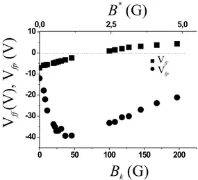
The floating potentials (with respect to the grounded anode) of the magnetic filter Vf fand the probe Vf pas func-tions ofBk, are shown in Fig. 3. The probe was located at 20 cm of the filter exit. Each point in the figure represents an average of3−5 arc discharges performed under iden-tical conditions. An individual measurement had a typical uncertainty of10%, due to the inherent noisiness of the arc plasma. It can be seen from Fig. 3 that Vf f<0forBk <75 G (Vf f(Bk=0) =−7V) while it becomes positive for higher values ofBk. Since the plasma potential is quite close to the anode potential, a positive value for Vf f indicates a strong magnetization of the electrons. On the other hand, Vf p is always negative, and shows a complex behavior with Bk, presenting a kind of “potential well”. In fact, Vf p varies from−12V atBk =0to−40V atBk ∼30G, and then slowly increases withBk, reaching the value Vf p(Bk=197 G) =−22V. It should be emphasized that the actualBvalue at the probe position (B∗) is in this experiment much
smal-ler than the conventionalBkvalue at the torus knee. For this reason, both values ofB(BkandB∗) have been plotted in
0 50 100 150 200 -40
-30 -20 -10 0
100,0 2,5 5,0
B
k(G)
B
*(G)
V
(V),
V
(V)
ff
fp VVff
fp
Figure 3. Vf f and Vf pas functions of the magnetic field at the
filter kneeBk(or equivalently, the magnetic field at the filter exit
B∗) with the probe located at L =20cm from the filter exit.
To study the influence of the probe on the filter floating potential, Vf f was measured for different biasing voltages of the probe (Vbp). The results are presented in Fig. 4, where Vf f is plotted againstBk for Vbp = −50V, Vbp =−30V and Vbp = Vf p. It can be seen from Fig. 4 that for small values ofBk (when Vf f 60) there is no clear dependence of Vf fon Vbp, but for high values ofBk(Bk >120G) Vf f slightly increases with the absolute value of Vbp.
0 50 100 150 200
-8 -6 -4 -2 0 2 4
0,0 2,5 5,0
B
*(G)
B
k(G)
V
(V)
ff
Vfp
V = - 30 Vbp
V = - 50 Vbp
Figure 4. Vf fas a function of the magnetic field at the filter knee
Bk(or equivalently, the magnetic field at the filter exitB∗), at
dif-ferent probe voltages (Vbpand Vf p) for probeA, with L =20cm.
In Fig. 5, the larger size probe current IpAas a function
of Bk, for different probe bias potentials (−50V and−30 V) and floating filter is presented. For Vbp = -50 V, IpA is
negative for lowBkvalues, and increases withBk, reaching positive values forBk>30G. The situation for Vbp=−30 V is quite similar to the previous one, but in this case IpA
re-aches positive values forBk >140G. The negative values of IpAregistered for lowBk values are consistent with the
high negative Vf pvalues shown in Fig. 3.
0 20 40 60 80 100 120 140 160 180 200 0
2 4
B
k(G)
I
(mA)
p
A
V = - 30 Vbp V = - 50 Vbp
Figure 5. Probe current IpAfor floating filter as a function of the
magnetic field at the filter kneeBkat different Vbpvalues, with L
=20cm.
A comparison between the ion current collected by pro-bes of different sizes is presented in Fig. 6. Both propro-bes were located at 20cm from the duct exit, biased at −50 V and with floating filter. The quotient between both cur-rents coincides approximately with the quotient between the probe’s areas, indicating a good homogeneity of the plasma at the probe’s position.
0 50 100 150 200 -1
0 1 2 3 4 5
B
k(G)
I(mA)
pProbe A Probe B
Figure 6. Probe current for floating filter as a function of the mag-netic field at the filter kneeBk, with different probe sizes, Vbp=
−50V and L =20cm.
100 120 140 160 180 200
0,0 0,5 1,0 1,5 2,0 2,5 3,0 3,5
B
k(G)
I
(mA)
p
B
L=20cm L=3cm
Figure 7. Probe current IpBfor floating filter as a function of the
magnetic field at the filter kneeBkat different positions from the
In order to investigate the plasma expansion at the filter’s exit, IpBwas registered at different distances from the filter.
This is shown in Fig. 7, where IpBis plotted as a function of
Bk for Vbp =−50V, floating filter, and L = 3and20cm, being L the axial distance between probe and filter’s exit. It can be seen that the shorter distance results in an increased IpBvalue (by a factor of∼6). ForBk=197G, the magnetic
fields at both probe locations are:B∗(L =3cm)=30G and B∗(L =20cm)=5G.
Figure 8 shows the curve IpAvs. Bk for different filter
bias voltages (Vbf), for Vp =−50V. Each point in Fig. 8 represents the average of several runs (typically3−5) per-formed under identical values of Vbf andBk. In practice, the value of Vbf could not be fixed “a priori” because the electron current collected by the filter produced a considera-ble voltage drop in the inner resistance of the biasing power source, thus resulting in a true Vbf equal to the prescribed biasing voltage minus the resistive source voltage drop. For arcs performed under the same nominal biasing filter volta-ges, the above-described effect resulted in the obtainment of a range of Vbfvalues (typically with an uncertainty of±0.5 V). It can be seen that IpAincreases withBk. For low values
ofBk(Bk<85G) negative values of Ip
Aare found for Vbf values close to the filter floating potential (see Fig. 3). Note that the maximum Vbf value in Fig. 8 is Vbf =6V. This is due to the fact that the filter, when biased positively, collects a considerable negative current from the main arc discharge. In practice, with the presently available bias source, it was not possible to raise the bias voltage beyond6V, because the biasing power source of the filter cannot withstand a current larger than≈20A. The amount of this current is strongly dependent on Vbf(see next Figure).
80 90 100 110 120 130 140 150 160 -2
0 2 4 6
8 1,0 1,5 2,0 2,5 3,0 3,5
B
k(G)
B
*(G)
I
(mA)
p
A V =3Vbf
V =4Vbf
V =3Vbf
V = 6Vbf
Figure 8. Probe current IpAas a function of the magnetic field at
the filter kneeBk(equivalently, the magnetic field at the filter exit
B∗) at different V
bfvalues and Vbp=−50V, with L =20cm. Figure 9 shows the probe current IpAand the current
col-lected by the filter If, as functions of Vbf forBk =154G and Vbp = −50 V. Each point in the figure represents the average of several runs (typically 3−5) performed under identical values of the nominal bias voltage. Note that If is negative (which means an electron current) and strongly increases (in absolute value) with Vbf, indicating that the filter is acting as a secondary anode for the main discharge.
For instance, for Vbf = 4V the filter collects20% of the discharge current forBk =154G.
0 1 2 3 4 4
6 8 10 12 14
-20 -16 -12 -8 -4 0
V (V)
b fI
(mA)
p
A
I
(mA)
fFigure 9. Probe current IpAand filter current If as functions of the
filter potential, with Vbp=−50V,Bk=154G and L =20cm.
4
Discussion and final remarks
We have presented in this work the first measurements per-formed with a magnetically filtered arc at INFIP (DCF2 de-vice). Although the optimization procedure is far from being complete (mostly due to the current limitation of the presen-tly available filter bias source), the presented results show some interesting features.
The dependence of the filter floating potential withBk is in agreement with previous published results by other authors [6, 9], being negative for small Bk values (when the electron flux reaching the filter still exceeds the ion flux) but becomes positive for highBkvalues (when the electrons are strongly magnetized, and cannot reach the filter). The behavior of the probe floating potential with Bk presents some peculiarities never reported before, likely because of the small values of the magnetic field at the probe position (B∗) at which these peculiarities are produced: the presence
of a deep “floating potential well” (Vf p ∼ −40V, corres-ponding toB∗∼1G) when the electrons are partially mag-netized (the electron Larmor radius is∼3cm forB∗ ∼1 G and an electron temperature Te∼ 2eV) can be explai-ned only in terms of changes in the plasma potential in the presence ofB, in the electron distribution function, and/or changes in probe charge collection theory. Note that this “potential well” has important practical consequences, be-cause a probe must be biased at voltages well below Vf pto collect a pure ion current.
object of large size where the embedded plasma changes its properties.
The Cu ion currents collected by the probes correspond to plasma densities of108
−109 cm−3
at the filter exit, de-pending on the operating arc conditions. These densities produce a Debye length (that is of the order of the thickness of the plasma sheath at the filter wall) in the range of0.3−1 mm for Te=2.7eV.
The best ion current collected at the filter exit amounts to≈12mA forBk=154G, a value still small as compared with the maximum ion current (≈8−10A) generated at the cathode surface for an arc discharge current of100A. The optimum ion current was obtained at a filter bias voltage of 4 V, when the filter, acting as a secondary anode, collected about 20 % of the main discharge current. This result indi-cates that to obtain an improvement in the ion transmission through the filter, the first task is to get a good matching between the plasma generation chamber and the filter en-trance, which will be done in the near future by generating a focusing magnetic field in the cathode-filter region so as to optimize the ion flux entering into the filter. Also, it is necessary to increase the filter bias voltage by employing a power source with a higher current capacity. The strong de-crease in the ion current as the probe-filter distance inde-creases (see Fig. 7) indicates that it is also necessary to increase the magnetic field at the probe location.
Acknowledgments
This work was supported by grants from the Universidad de Buenos Aires (PID X214) and from the Agencia Nacional de Promoci´on Cient´ıfica y Tecnol´ogica (PICT 03-09491).
References
[1] R. L. Boxman, D. M. Sanders, and P. J. Martin, Handbook of Vacuum Arc Science and Technology, Fundamentals and Applications, Park Rige, NJ: Noyes, 1995.
[2] I. G. Brown, B. Feinberg, and J. E. Galvin, J. Appl. Phys. 63, 4889 (1988).
[3] G. Y. Yushkov, A. Anders, E. M. Oks, and I. G. Brown, J. Appl. Phys. 88, 5618 (2000).
[4] C. W. Kimbling, J. Appl. Phys. 44, 3074 (1973).
[5] I. I. Aksenov, V. A. Belous, V. G. Padalka, and V. M. Kho-roshikh, Sov. J. Plasma Phys. 4, 425 (1978).
[6] B. Cluggish, IEEE Trans. Plasma Sci. 36, 1645 (1998).
[7] V. N. Zhitomirsky, O. Zarchin, R. L. Boxman, and S. Golds-mith, Proc. 20th Int. Symp. on Discharges and Electrical In-sulation in Vacuum (Tours, France), 670 (2002).
[8] H. Kelly, L. Giuliani, and F. Rausch, J. Phys. D: Appl. Phys.
36, 1980 (2003).
[9] A. Anders and S. Anders, and I. Brown, Plasma Source Sci. Technol. 4, 1 (1995).
[10] R. L. Boxman, V. N. Zhitomirsky, B. Alterkop, E. Gidalevich, M. Keidar, and S. Goldsmith, Surf. Coat. Technol. 86-87, 243 (1996).
[11] S. H. Lam, Phys. Fluids 8, 73 (1965).