Tatiana Vidal Candéa
Graduated in Food Engineering
Study of membrane emulsification process
as a pre-step for the microencapsulation of
lipid compounds by spray drying
Dissertation for obtaining the Master degree in Membrane
Engineering
Erasmus Mundus Master in Membrane Engineering
Advisor: Lourdes Cabral, Researcher, Embrapa Food
Technology
Co-advisor(s): Renata Tonon, Researcher, Embrapa
Food Technology
Isabel Coelhoso, Professor, FCT-UNL
João G. Crespo, Professor, FCT-UNL
Jury:
President: João G. Crespo, Professor, FCT-UNL Members: André Ayral, Professor, UM2
Patrice Bacchin, Professor, UPS Karel Bouzek, Professor, ICTP Luisa Neves, Researcher, FCT-UNL
III
Tatiana Vidal Candéa
Graduated in Food Engineering
STUDY OF MEMBRANE EMULSIFICATION
PROCESS AS A PRE-STEP FOR THE
MICROENCAPSULATION OF LIPID
COMPOUNDS BY SPRAY DRYING
Dissertation presented to Faculdade de Ciências e Tecnologia, Universidade Nova de Lisboa for obtaining the master degree in Membrane Engineering
IV TITLE
The EM3E Master is an Education Programme supported by the European Commission, the European Membrane Society (EMS), the European Membrane House (EMH), and a large international network of industrial companies, research centres and universities (http://www.em3e.eu).
Copyright @ Name, FCT/UNL
A Faculdade de Ciências e Tecnologia e a Universidade Nova de Lisboa têm o direito, perpétuo e sem limites geográficos, de arquivar e publicar esta dissertação através de exemplares impressos reproduzidos em papel ou de forma digital, ou por qualquer outro meio conhecido ou que venha a ser inventado, e de a divulgar através de repositórios científicos e de admitir a sua cópia e distribuição com objectivos educacionais ou de investigação, não comerciais, desde que seja dado crédito ao autor e editor.
V ACKNOWLEDGMENTS
I would never have been able to finish my master without the guidance of my committee members, help from friends, and support from my family and fiancé.
I was blessed to be surrounded by a group of advisors and researchers that gave me their assistance and guidance with this thesis. I would like to express my gratitude to my advisory committee: Dr. Lourdes Cabral, Dr. Renata Tonon, Dr. Jõao Crespo, Dr. Isabel Coelhoso. It has been an honor to work with Dr. Lourdes once more. Special thanks to Dr. Renata for her time, patience and understanding. Also, thanks to Dr. Gilbert Rios for giving me the opportunity to work at Embrapa.
I would to thank to all my friends that constitute the Embrapa family, including Dr. Virgínia da Matta, Janine, Luiz Fernando, Filé, William, Rozana, Leilson, Carla, Flávia Pingo, Juliana, André, Renata Cabral, Marcela, Aline, Laís, Ana Paula and Diego that provided an excellent atmosphere for doing research. Special thanks also to Dr. Flávia Gomes and Dr. Mônica Pagani, as good friends, were always willing to help and give their best suggestions. Dr. Damien Quémener and Dr. Luisa Neves for their willingness to help me.
My gratitude also is to the kindness support received by the other laboratories at Embrapa and at UFRJ that allowed me to use their equipments. Without this I would not be able to finish my research. Thanks to Mariana, Adriana Minguita, Jorge, Dr. Carlos Piller, Selma, Erika, Simone, Vanessa, Dr. Ana Lucia, Isabelle, Dr. Suelly Freitas, Larissa, Rana and Luciana. Special thanks to the logistic Embrapa team: Sônia, Hildomar, Jorge and Fagundes that helped me with the sample transportation.
I would like also to thank the European Union for the financial support, as well as the Membrane house for the great initiative and help on the creation of this master program.
I would like also to thank my dear EM3E friends for all the support during the one and half year that we lived together. You showed me many different things that provided me personal and professional growth. I love you all and I miss you with all my heart.
VI Abstract
Food emulsions play an important role in product development and formulation, as well as to encapsulation of food additives. Conventional methods for emulsion production may present some drawbacks, such as the use of high shear stress, high energy demanding and polydisperse droplet size distribution. In this sense, membrane emulsification emerges as an alternative method to overcome all this issues and to produce fine and stable emulsions. Linseed oil has been widely studied in the last years, due to its nutritional composition, being the richest ω-3 vegetable source and for that reason it was used as the raw material for emulsion production. Premix and direct (cross flow) membrane emulsification were carried out using three different membrane materials: polissulphone, cellulose ester and α-alumina membrane. For premix membrane emulsification (PME) the variables transmembrane pressure, membrane material, surfactant type and membrane mean pore size were evaluated. The membrane mean pore size was the crucial factor to achieve emulsions by PME, once it was not possible to achieve stable emulsion with mean pore sizes lower than 0.8 μm. For direct membrane emulsification, transmembrane pressure, surfactant concentration and cross flow velocity were evaluated by means of a experimental design. The evaluated responses were stability, droplet size and distribution and dispersed phase flux. For all the variables studied, only dispersed phase flux showed to have significant influence of pressure. Comparing both methods of membrane emulsification, premix showed to be more suitable in terms of emulsion production throughput and droplet size correlation with membrane pore size, however, in terms of stability, direct membrane emulsification showed much better results. Encapsulation of linseed oil by spray drying was promoted using the optimum point of the performed experimental design and the droplets size distribution has considerably changed with the addition of the wall material to the emulsion.
VII
Index
1
INTRODUCTION ... 1
1.1
Background and Motivation ... 1
1.2
Objectives ... 3
2
LITERATURE REVIEW ... 5
2.1
Emulsions ... 5
2.2
Membrane emulsification ... 6
2.2.1 Cross-flow ME ... 10
2.2.2 Premix ME ... 11
2.3
Parameters affecting the emulsion production ... 12
2.3.1 Membrane parameters ... 13
2.3.2 Process Parameters ... 14
2.3.3 Emulsion properties ... 15
2.4
Linseed oil ... 15
2.5
Encapsulation ... 16
3
MATERIALS AND METHODS ... 19
3.1
Materials ... 19
3.2
Emulsion preparation ... 20
3.2.1 Premix emulsification ... 20
3.2.2 Direct membrane emulsification ... 22
3.3
Membrane characterization ... 23
3.3.1 Scanning electron microscopy (SEM) ... 23
3.4
Emulsion characterization ... 24
3.4.1 Viscosity... 24
3.4.2 Density... 24
3.4.3 Microscopy ... 24
3.4.4 Particle size distribution ... 24
3.4.5 Emulsion stability ... 25
3.4.6 Statistical analyses ... 25
3.5
Microencapsulation by spray drying ... 25
4
RESULTS AND DISCUSSION ... 27
VIII
4.2
Direct Membrane Emulsification (DME)... 41
4.3
Comparison between emulsification methods ... 51
4.4
Microencapsulation by spray dryer ... 55
5
CONCLUSION AND FUTURE PERSPECTIVES ... 58
IX
Index of figures
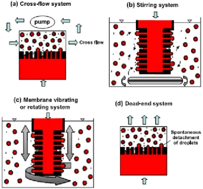
Figure 1. Membrane emulsification systems for controlling hydrodynamic conditions near the membrane
surface (Vladisavljevic & Williams, 2005). ... 9
Figure 2. The forces acting on the droplets during membrane emulsification (Hancocks et al., 2013). .... 10
Figure 3. Schematic diagram of cross-flow membrane emulsification (Adapted from Liu et al., 2010) ... 11
Figure 4. Schematic diagram of premix membrane emulsification (Adapted from Liu et al., 2010) ... 12
Figure 5. Effect of wall shear stress on droplet size in oil-in-water emulsions produced using ME ... 15
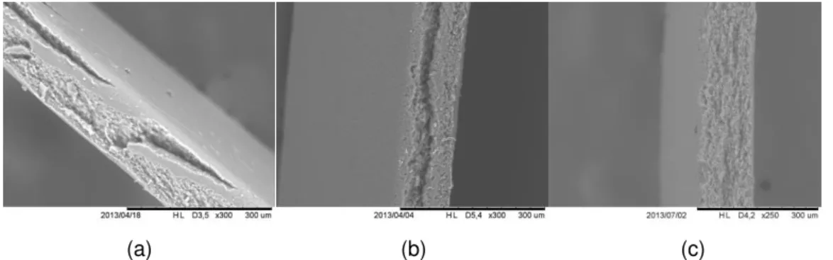
Figure 6. Electron micrograph of flat membranes, cellulose nitrate (a), cellulose acetate (b) and mixed cellulose ester (c) ... 19
Figure 7. Electron micrograph showing the ceramic membrane layers on top of a more open support layer (Source: PALL coroporation, Membralox® Ceramic Membrane Products) ... 19
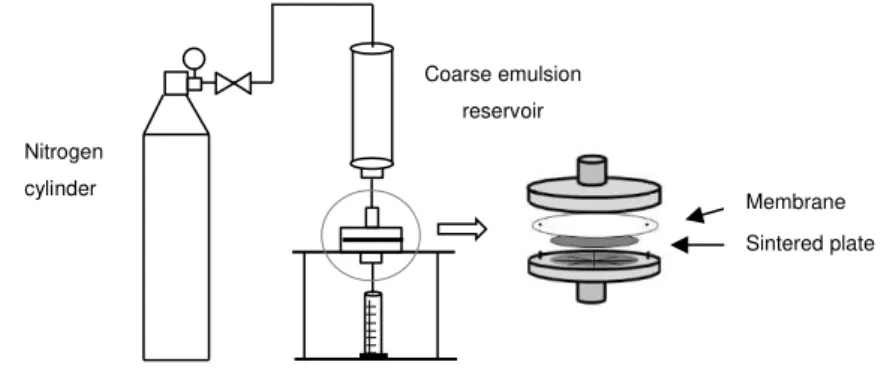
Figure 8. Schematic representation of the premix membrane emulsification with agitation ... 21
Figure 9. Schematic representation of the premix membrane emulsification without agitation ... 21
Figure 10. Schematic representation of the direct membrane emulsification ... 22
Figure 11. Mini spray dryer Buchi Modelo B-190 ... 26
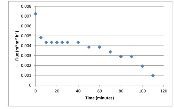
Figure 12. Evolution of the permeate fluxes along premix membrane emulsification process with 0.1µm polissulphone (PST80) ... 27
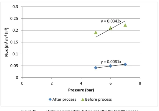
Figure 13. Hydraulic permeability before and after the PST80 process ... 28
Figure 14. Retentate and permeate fraction of premix emulsification using polysulphone (0.1μm) membrane ... 28
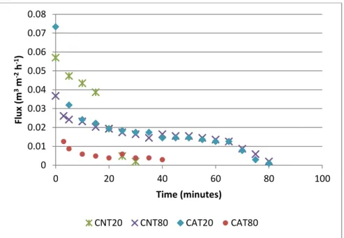
Figure 15. Evolution of the permeate flux during the premix emulsification processes with cellulose ester membranes (CN and CA) and Tween 20 (T20) and Tween 80 (T80) as surfactants ... 30
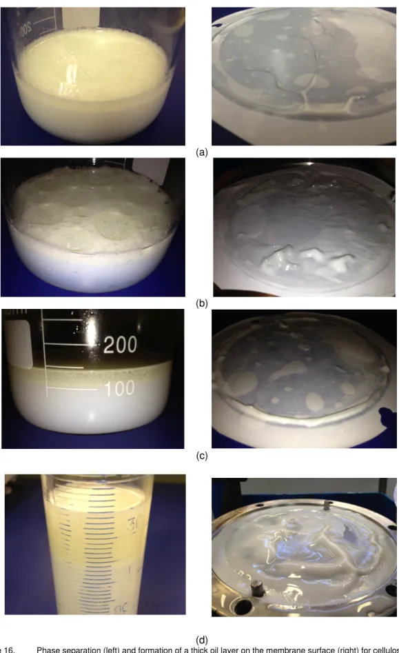
Figure 16. Phase separation (left) and formation of a thick oil layer on the membrane surface (right) for cellulose ester membrane emulsification for the processes CNT20 (a), CNT80 (b), CAT 20 (c) and CNT 80 (d). ... 31
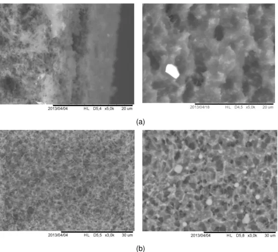
Figure 17. Transversal (a) and frontal (b) SEM images of new (on the left) and used (on the right) cellulose acetate membrane with mean pore size of 0.45 μm. ... 32
Figure 18. Transversal (a) and frontal (b) SEM images of new (on the left) and used (on the right) cellulose nitrate membrane with mean pore size of 0.22 μm. ... 33
Figure 19. Flux of emulsion using celulose acetate and Tween 20 as surfactant with (CAT20B) and without (CAT20) pretreament with surfactant solution. ... 34
Figure 20. Comparison between the permeate fluxes obtained with agitated and non-agitated module. ... 35
Figure 21. Photomicrograph of coarse emulsion (left) and emulsion achieved by process AMCT20 (right). ... 36
Figure 22. Stability of linseed oil emulsion prepared by PME 1. ... 37
Figure 23. Flux against pressure for processes PME1, PME 2, PME 3. ... 38
Figure 24. Photomicrograph with 400x magnification of emulsion prepared by PME 1 (a), PME 2 (b) and PME 3 (c). ... 38
Figure 25. Droplet size distribution of processes PME 1, PME 2 and PME 3. ... 39
Figure 26. Particle size distribution of the process PME 2 accomplished on cycles. ... 40
X
Figure 28. Pareto chart for the dispersed phase flux in cross flow membrane emulsification. ... 43
Figure 29. Droplet size distribution of linseed oil emulsions produced by cross flow membrane emulsification. ... 44
Figure 30. Pareto chart for surface weighted mean diameter in cross flow membrane emulsification ... 45
Figure 31. Pareto chart for volume weighted mean diameter in cross flow membrane emulsification ... 45
Figure 32. Pareto chart for span in cross flow membrane emulsification ... 46
Figure 33. Separation of linseed oil cross flow membrane emulsification ... 47
Figure 34. Pareto chart for % of phase separation in cross flow membrane emulsification ... 47
Figure 35. Photomicrographs of linseed oil cross flow membrane emulsification in the first day (left) and twenty-first (right) ... 51
Figure 36. Photomicrographs of Ultra-Turaax emulsification (a), premix ME (b) and direct ME (c) ... 53
Figure 37. Droplet size distribution for emulsion achieved by Ultra-Turrax, direct ME and premix ME ... 53
Figure 38. Stability for 7 days of emultion achieved by turaax emulsification (a), premix ME (b) and direct ME (c) ... 54
XI
Index of tables
Table 1 . Membrane emulsification studies ... 8
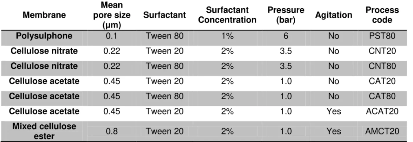
Table 2 . Description of emulsion formulations and process parameters ... 20
Table 3 . Codified independent variables ... 23
Table 4 . Results obtained for premix membrane emulsification performed with agitated module. ... 36
Table 5 . Surface weighted (D[3,2]), volume weighted D[4,3] and span values for processes PME 1, PME 2 and PME 3. ... 39
Table 6 . Flux and droplet size parameters for the process PME 2 accomplished on cycles ... 40
Table 7 . Flux, droplet size and stability results for linseed oil cross flow membrane emulsification .... 42
Table 8 . ANOVA analisys of adjusted model for flux. ... 43
Table 9 . Emulsion flux by Premix and direct ME ... 52
Table 10 . Span, Sauter and De Brouckere mean diameter for emulsion achieved by Ultra-Turrax, direct ME and premix ME, ... 54
1 1 INTRODUCTION
1.1 Background and Motivation
Nowadays, it is widely recognized that the creation of novel foods or the improvement of existing foods depends on a better understanding of the complex interrelationship between food structure and performance (McClements et al., 2009).
In the last two decades or so the perception of food has changed from being just hunger satisfiers and taste bud entertainers to a source of healthy well-being. This increased consumers interest has led to the emergence of a specialized category of food products, commonly known as the functional foods, which relies on fortification of food products with micro-nutrients or functional ingredients from natural sources or relatively novel combination of food ingredients, such as, for example fibre added to soft drinks, fish oil added to bread or human gut bacterial cultures added to dairy foods (Day et al., 2009).
The addition of ω-3 and ω-6 polyunsaturated fatty acids (PUFA) to functional food ingredients and their consumption in dietary supplements have experienced significant increases (O’Brien, 2009). These fatty acids have been associated with a variety of health benefits, such as reducing the risk of coronary heart diseases, hypertension, arthritis, and immune response disorders (Rubio-Rodríguez et al., 2010). Linseed oil is a healthful and nutritive oil very rich in unsaturated fatty acids, being recognized as one of the greatest vegetable Omega-3 sources in nature, which represents about 57% of its total fatty acids (Zhao et al., 2004).
There are basically two ways of adding (functional) ingredients to a product: In a soluble form as solution or insoluble form as dispersion (Patel & Velikov, 2011). In terms of bioactive lipids, both methods involve emulsion production and can be done by means of emulsion production by itself or microencapsulation.
Emulsions play an important role in the formulation of foods for production of oil in water (o/w) emulsions, e.g., dressings, artificial milks, cream liqueurs, as well as for preparation of some water in oil (w/o) emulsions, e.g., margarines and low fat spreads. Some emulsions are end products themselves, e.g., coffee creamers and cream liqueurs are relatively simple emulsions which remain stable towards creaming and coalescence during their production and shelf-life. Besides, emulsions can also be used as ingredients, which participate in forming the structures of more complex products. For example, yoghourts and other gelled systems contain emulsion droplets that must interact with other food ingredients, but that must not be destabilized in the process. Finally, the emulsion droplets may create new structures, i.e., in ice-cream or whipped products, where the emulsion is itself required to destabilize as a means to creating structure in the product (Charcosset, 2009). And thus, functional ingredients could be used as the raw material to obtain functional products.
2 handling, storage, and delivery of the powder-like materials produced. In the food industry, the most widely employed technologies for encapsulating lipophilic compounds are based on the production of an oil-in-water (O/W) emulsion which is then followed by either spray drying, freeze drying, molecular inclusion, enzymatic gelation, or coacervation. Of these techniques, the most common way of producing encapsulated oil is by spray drying the emulsion because it is a very efficient and flexible process that quickly removes water by vaporization and that can be carried out with readily available equipment (Ramakrishnan et al., 2012).
Implementing additional functional ingredients to food products often leads to problems ranging from formulation difficulties, taste issues, product stability, product appearance and decreased bio-accessibility. What makes it even more challenging is the interaction of these functional ingredients with the complex product matrix (Patel & Velikov, 2011).
Many different emulsification methods have been developed, mostly depending upon the product (and economical) requirements. Conventionally, the emulsions are prepared by mechanical disruption of the dispersed phase droplets into the continuous phase. Colloid mills, rotor stator systems, high-pressure homogenizers, and ultrasonic homogenizers are popular types of equipments for this, due to their high throughput. Although these systems result in stable emulsions, they have high energy requirements, apply shear and extensional stresses to the product that may cause loss of functional properties of heat and shear sensitive components. In addition, they show poor control over droplet size and distribution (Joscelyne & Trägårdh, 2000; Charcosset, 2009; Nazir et al., 2010).
The size and uniformity of emulsion droplets are of critical importance, since they determine the stability against coalescence and fitness in application to some extent (Zhou et al., 2009), being fine emulsions more stable than the coarse emulsions. Besides, the droplet size distribution affects many of the physicochemical emulsion properties (Charcosset, 2009).
There are several advantages to produce fine emulsions: Systems with fine and well controled particle/droplet size reduces the sensitivity to the oil with respect to the human taste sensation, and it would reduce the effect of an emulsion or microcapsule on the taste of the food itself (Shima et al., 2004; Patel & Velikov, 2011). In addition, because w/o food products (e.g. margarine) contain flavouring components in the dispersed phase, the droplet size distribution affects the flavour of such products. Furthermore, it may also have a great effect on growth bacteria. When the droplet diameter is large, bacteria multiply more easily than for smaller droplet diameter, as the bacterial growth is reduced due to the lack of nutrients inside the droplets (Charcosset, 2009).
As this parameter is direct correlated to emulsion stability, it is also one of the most important parameter that affects the microencapsulation process. In general more stable emulsions results in greater encapsulation efficiency, in other words, in smaller amount of non-encapsulated material on the particle surface (Minemoto et al., 2002; Barbosa et al., 2005).
3 mechanical stress (Schröder et al., 1998) or even without any shear (Kosvintsev et al., 2008), being relatively simple, with considerably lower energy requirement than traditional processes, lower surfactant requirement and narrow droplet size distribution (Joscelyne & Trägårdh, 2000; Van Der Graaf et al., 2005; Charcosset, 2009; Dragosavac et al, 2012). Moreover, this technique allows the emulsion formation by means of two methods: crossflow or direct emulsification, which is based in a primary homogenization where the dispersed phase is pressed to pass through the membrane while the continuous phase flows on the other side of the membrane, and premix emulsification, which is based in a secondary homogenization, since it consists in the reduction of the droplet size of the already formed coarse emulsion.
Membrane emulsification has as a great advantage, the possibility to be applied to both kinds of compounds, lipophilic by means of O/W emulsions (Trentin et al., 2011; Ramakrishnan et al., 2012) and hydrophilic by means of water-in-oil-in-water (W/O/W) double emulsions (Shima et al., 2004; Vladisavljevic et al., 2004; Van der Graaf et al., 2005).
A lot of work has been carried out on membrane emulsification on the last 20 years. However just in the last 15 years with the introduction of premix membrane emulsification, by Suzuki and coworkers (1998) more types of membranes has been studied for this application besides Shirasu Porous Glass (SPG). This membrane has been widely used in many research fields (Vladisavljevic et al., 2003; Toorisaka et al, 2003; Vladisavljevic et al., 2004a; Kukizaki & Goto, 2007; Hancocks et al., 2013), but it would be potentially unsuitable for food production due to its fragility, possibility of glass contamination in the product and other factors (Hancocks et al., 2013). In this sense, other membrane types with narrow pore size distribution are being used, such as etched nickel film and micro-sieves with engineered pores often made using silicon (Wagdare et al., 2010; Dragosavac et al, 2012; Nazir et al, 2013) however these membranes have high cost and they are potentially prohibitive to scale-up.
Despite of this, there are few works in the literature reporting the application of different membrane materials with small pore size for membrane emulsification. Furthermore, most of the studies in this field is devoted to encapsulation in liquid media, aiming just the entrapment of the material on the lipid matrix. Only one recent study (Ramakrishnan et al., 2012) focused on the production of microcapsules by combining membrane emulsification with spray drying.
Thus, the aim of this work was to study two types of membrane emulsification processes (premix and cross-flow emulsification), as a pre-step for microencapsulation of linseed oil by spray drying.
1.2 Objectives
The objective of this work was the encapsulation of linseed oil by means of a combination of membrane emulsification processes using commercial (unstructured) membranes and drying by atomization (spray drying) in order to obtain stable emulsions and powders.
The specific objectives are:
4
To study the effect of surfactant type, transmembrane pressure, pore size and presence or absence of agitation on the premix emulsification;
To understand the behavior of emulsion in each cycle of multi-stage premix membrane emulsification;
To verify the influence of surfactant concentration, cross flow velocity and transmembrane pressure on the dispersed phase flux of direct membrane emulsification;
To characterize the emulsions produced by both methods in terms of creaming stability, droplet size and its distribution;
To compare direct and premix emulsification methods;
5 2 LITERATURE REVIEW
2.1 Emulsions
Emulsions are disperse systems of two immiscible or poorly miscible liquid phases. Examples for emulsions paints, spreads, cosmetic creams, pharmaceutical ointments and sauces. Food emulsions examples are mayonnaise, which is small oil droplets dispersed in a continuous water phase (oil-in-water emulsion, o/w) or margarine consisting of small water droplets dispersed in a continuous oil phase (water-in-oil emulsion, w/o). Moreover, emulsions play an important role in the formulation of various other products as ingredients like salad dressings, artificial milks, cream liqueurs, sausage, pate, etc. Above that, it is possible to disperse a primary emulsion, e.g. a w/o emulsion in a continuous phase, e.g. water, which results in the formation of a double emulsion (water-in-oil-in-water emulsion, w/o/w). This type of emulsions contain small primary water droplets within larger oil droplets while the oil droplets are dispersed within the secondary continuous water phase. In the second step of the emulsification process, when the W/O/W droplets are produced, carefully controlled shear needs to be applied as there is a requirement not to rupture the primary emulsion (Lambrich & Schubert, 2005; Dragosavac et al., 2012).
Macro emulsions are thermodynamically and intrinsically instable and tend to destabilize due to several effects. Coalescence, an irreversible process, leads to the formation of larger droplets due to the fusion of two or more droplets. Coalescence may occur in the emulsification process or thereafter and can be reduced by specific ingredients namely surfactants or surfactants, which are chemical substances (or a mixture of substances) that occupy the interface between the oil and the water phase, forming protective layers and thus stabilizing the droplets against coalescence and/or aggregation and reducing the interfacial tension. The dynamics depend on the molecular structure of the surfactant. Depending on the emulsion to be produced and the surfactant type used, the surfactant can be diluted in the oil or the water phase (Joscelyne & Trägårdh, 2000; Dickinson, 2003; Lambrich & Schubert, 2005; Schoën et al., 2013).
6 processing, the much lower level of shear that the system is subjected to, and also the fact that far greater control over the formed emulsion microstructure can be achieved (Spyropoulos et al., 2011).
Schubert (1997) has compared the performance of different types of continuous emulsification equipment, namely high pressure homogenizers, rotor-stator systems and membrane emulsification, in terms of energy densities E
v
(J m-3) given the criteria of smallest drop size and narrowest distribution.In all cases higher energy densities were needed to produce smaller droplets. Droplet size ranged from about 100μ
m down to 0.2μ
m. For membrane systems the droplet size increased for a given energy density as the concentration of dispersed phase (expressed as volume fraction) increased from 0.05 to 0.8. Energy densities for membrane emulsification (between 103and 106J m-3) were some 100 times less than those demanded by high pressure homogenization (between 105 and 108 J m-3 ) and some 10 times less than rotor-stator methods (range of 105–107 J m-3). At a similar energy density, membranes produce smaller droplets, because less energy is lost as heat. However, if the dispersed phase viscosity and/or volume fraction is large, emulsification systems based on turbulent flow are more suitable. Droplet size distributions of turbulence-based methods tend to be broad given the nature of turbulence generation, making them more sensitive to creaming and Ostwald ripening.2.2 Membrane emulsification
Membrane processes have become major tools in the food processing industry over the last 25 years, with the classical reverse osmosis, nanofiltration, ultrafiltration, and microfiltration processes. Membrane systems are particularly suitable for large scale production because they are easy to scale-up, by adding more membranes to a device. The main applications of membranes are the dairy industry (close to 40%, of which over 10% are used for milk protein standardization), followed by beverages (wine, beer, fruit juices, etc.) and egg products (2%). Other fields are emerging: fruit and vegetable juices and concentrates, waste streams, co-products (recovery and recycling of blood plasma in abattoirs), and technical fluids (brines, cleaning-in-place solutions). The membrane emulsification process is also expected to gain an increasing interest in the food processing industry (Charcosset, 2009).
The concept of membrane emulsification has been around for many years, but the capabilities of the process are yet to be fully utilized and explored, particularly for use in the food industry where membrane emulsification is currently considered too low throughput for large-scale production (Gijsberten-Abrahamse et al., 2004). As far as the authors concern, just Morinaga Company in 1996 experimented with membrane emulsification to launch a low fat spread based on this technology (Schroën et al, 2012). However
,
membrane emulsification may be more suitable for use in producing of individual ingredients with carefully controlled structural properties (controlled droplet size, double emulsions for applications such as in healthier foods like reduced salt or fat content products or the pharmaceutical industry (Hancocks et al, 2013).7 emulsions by means of cross-flow membrane emulsification. Since this time the method has continued to attract attention due to its effectiveness in producing narrow droplet size distributions at low energy consumption. More recently (1998), premix membrane emulsification was introduced by Suzuki and co-workers as an alternative technique of membrane emulsification based on direct membrane emulsification.
Membrane emulsification involves using a low pressure to force the dispersed phase to permeate through a membrane, forming fine emulsions with a uniform pore-size distribution. The distinguishing feature is that the resulting droplet size is controlled primarily by the choice of membrane and not by the generation of turbulent droplet break-up. The technique is highly attractive given its simplicity, potentially lower energy demands, need for less surfactant and the resulting narrow droplet-size distribution (Joscelyne & Trägårdh, 2000).
The mechanism of droplets formation in membrane emulsification is quite different and involves two stages: droplet growth (when the droplet inflates at the pore tip) and droplet detachment (when the droplet breaks off and then moves away from the pore tip) (Charcosset, 2009).
8
Table 1 . Mem brane em ulsification studies
Membrane material
Mean pore size dm (μm)
Flux (m3 m-2 h-1)
Pressure
(kPa) System Authors
Flat PTFE 1.0 up to 9 - Premix dead end Suzuki et al, 1998
Flat PTFE 1.0 1 - 5.5 100-800 Premix dead end with
phase inversion Suzuki et al, 1999
Tubular α
-alumina 0.2; 0.5 0,007-0.15 20 or 40 Direct cross-flow Joscelyne &
Trägårdh, 1999
Tubular zirconia
coated 0.1 0.01 or 0.14 100 or 250 Direct cross-flow
Flat PTFE 1.0 2-18 - Premix dead end,
multistage (n=1–3)
Altenbach-Rehm et al, 2002
Tubular SPG 1.1 1,6 - Premix dead end, multi-stage (n=3) Toorisaka et al, 2003
Flat cellulose Cellulose acetate
0.2; 0.45; 0.8;
3 Not specified 300-440 Premix dead end Shima et al, 2004
Tubular SPG 0.4-6.6 0.0012-0,08 5-50 Direct cross-flow Vladisavljevic
et al., 2004a
Tubular α
-alumina 1.4 and 0.5 0.009-0.024 5-140 Direct cross-flow
Tubular SPG 10.7 0.85 – 37 20-150 Premix dead end,
multi-stage (n=1-5)
Vladisavljevic et al., 2004b
Tubular α
-alumina 1.5 0.42-0.62 200 Premix stirring Jing et al, 2005
Flat
polycarbonate - 3.7-14.7 -
Premix dead end,
multi-stage Yafei et al, 2006
Tubular stainless
Steel 100 - 0.3 Direct rotating
Vladisavljevic & Willians, 2006
Tubular
assimetric SPG 0,67
0.011 -
0.039 35-120 Direct cross-flow
Kukizaki & Goto, 2007
Tubular SPG 8.0 70 at n=5 100 Premix dead end, multi-stage Surh et al, 2007
SPG 5.0 - 120 Premix continuous Li & Sakaki, 2008
Tubular SPG 8.0 1 - 30 100-150 Premix dead end
multistage(n=1-5) Surh et al, 2008
Tubular SPG 4,8 0,05 90 Direct cross-flow Gutiérrez et al., 2009
Tubular SPG
hydrophilic 0.2; 0.4 0.03; 0.04 600 Direct cross-flow
D´oria et al., 2009
Tubular SPG
hydrophobic 0.4; 1 0.06; 0.84 600 Direct cross-flow
Tubular SPG 5.4; 7.6; 9.9
and 14.8 11.8 - 114.2 25 - 200 Premix dead end Kukizaki, 2009b
Flat Nylon 0.8 10.8 – 36 300-900
Premix dead end
multistage (n=4-5) Trentin et al, 2010
Flat PES 0.8 3.6 – 129 300-900
Flat Nitrocellulose
mixed ester
0.8 7.2-45 300-900
Flat Nickel 10; 20; 30 or
40 0.3 – 3.2 -
Premix and crossflow with stirring
Dragosavac et al, 2012
Flat
Polycarbonate 3; 5 2.304 – 16.2 manual
Premix dead end, multi-stage (n=1-3)
Cheetangdee & Fukada, 2012
Flat nickel sieves 7.1-13.2 - 50-200 Premix dead end
multistage(n=1-5) Nazir et al, 2013
Tubular SPG 0.2-10 - 60 Direct cross flow
Hancocks et al., 2013
Tubular titanium
oxide 0.5-10 - 60 Direct cross flow
Tubular
polymeric 1 and 1.5 - 60 Direct cross flow
Tubular stainless
Stainlees steel 15 - 60 Direct cross flow
9 Emulsions using membranes can be achieved by means of a regular droplet detachment from the pore outlets where a shear stress is generated at the membrane/ continuous phase interface by recirculating the continuous phase using a low shear pump (Fig. 1a), or by agitation in a stirring vessel (Fig. 1b). Another approach uses systems equipped with a moving membrane, in which the droplet detachment from the pore outlets is stimulated by rotation or vibration of the membrane within a stationary continuous phase (Fig. 1c). Even in the absence of any tangential shear, droplets can be spontaneously detached from the pore outlets at small disperse phase fluxes (Fig. 1d) (Vladisavljevic & Williams, 2005).
Figure 1. Membrane emulsification systems for controlling hydrodynamic conditions near the membrane surface
(Vladisavljevic & Williams, 2005).
10
Figure 2. The forces acting on the droplets during membrane emulsification (Hancocks et al., 2013).
As a rule, the dispersed phase should not wet the membrane pores, otherwise the dispersed phase will stick to the membrane and form large droplets. This means that hydrophilic membranes are suited to making o/w emulsions and hydrophobic membranes for w/o emulsions (Joscelyne & Trägårdh, 2000; Schroën et al., 2012).
Membrane emulsification (ME) methods are mainly direct ME and premix. According to Schroën et al. (2012) in spite of many parameter studies that had been carried out on both methods, it is not possible to bring the various results for either technique together in a comprehensive framework or model, due to the numerous parameters that play a role and the complexity of the process.
2.2.1 Cross-flow ME
11
Figure 3. Schematic diagram of cross-flow membrane emulsification (Adapted from Liu et al., 2010)
Cross-flow emulsification has advantages such as low and constant shear stresses along the membrane surface, low energy requirement, uniform droplet size, which allow use of less surfactant, and ease of design and scale up. A limitation in case of cross-flow emulsification is the low dispersed phase flux through the membranes (typically 0.01–0. 1 m3
m-2 h-1), leading to low productivity and therefore recirculation is often required to increase the amount of disperse phase. In that case, this recirculation may induce breakage of the droplets inside the pipes and pump, leading to a considerable polydispersity (Egidi et al., 2008; Vladisavljevic et al., 2012; Dragosavac et al., 2012). Besides, the required membrane area is rather large, and this makes this technology expensive for large-scale application. Furthermore, it is difficult to prepare uniform emulsion droplets when the dispersed phase has high viscosity; and uniform emulsion can only be prepared using a porous membrane with very uniform pores. For ‘diluted’ (up to 30 vol %) specialty products that need to meet high quality standards, cross-flow emulsification is however an interesting technique to consider (Mcclements, 2005; Liu et al., 2010; Nazir et al, 2010;Dragosavac et al., 2012)
Most of the published investigations for direct ME have been made using tubular micro-porous glass (MPG) membranes (Asahi Glass Company, Japan) and Shirasu porous glass (SPG). These membranes are reputed as having cylindrical, interconnected, uniform micropores. However, also Ceramic α-Al2O3 (e.g., Membraflow, Germany and Membralox, SCT France) or α-Al2O3 coated with titanium oxide or zirconia oxide have been used (Joscelyne & Trägårdh, 2000).
2.2.2 Premix ME
Premix membrane emulsification consists of a preliminarily emulsified coarse emulsion passing through a porous membrane. The coarse emulsion can be achieved by mixing the two immiscible phases (oil and aqueous phases) together using a conventional stirrer mixer. In most cases, a membrane is used that is wetted by the continuous phase of the premix and the emulsion is broken up into smaller droplets (McClements, 2005; Liu et al., 2010; Nazir et al, 2010).
12
Figure 4. Schematic diagram of premix membrane emulsification (Adapted from Liu et al., 2010)
Studies indicated that premix ME provides several advantages over cross-flow ME. The energy costs for premix emulsification are relatively low, since no cross-flow is needed. The energy needed can be one order of magnitude lower than for cross-flow emulsification for highly concentrated products, the optimal flux with regard to droplet uniformity is much higher than 1.0 m3
m-2 h-1), the average droplet size is smaller with the same membrane and phase compositions, the experimental set-up is generally simpler than that in direct ME; and the process parameters are easier to control. Besides, the driving pressure and emulsifier properties are not critical in the premix ME operation as in the direct ME process (Liu et al., 2010).
The main drawback of premix emulsification is membrane fouling that may become serious depending on the formulation components, and related to that their interaction with the membrane and their ease of removal. Moreover, there are other disadvantages such as a higher polydispersity of emulsion droplets, since the membranes used does not have as narrow pore size distribution as SPG membranes, for that reason, in general the desired emulsion cannot be produced in a single passage (Liu et al., 2010; Nazir et al., 2010).
Further homogenization by repetitive cycles, commonly termed as repeated or multi-stage premix emulsification, where the coarse emulsion is repeatedly forced through the same porous membrane a number of times to achieve fine and uniform-sized emulsion droplets, yields better control of droplet size and distribution, however, at a corresponding increase of the overall energy input. In (repeated) premix emulsification, the transmembrane pressure is utilized to overcome flow resistances inside the pores and for droplet disruption to overcome interfacial tension forces (Nazir et al., 2010).
2.3 Parameters affecting the emulsion production
13 2.3.1 Membrane parameters
Several authors have shown that the average droplet diameter, dd , increases with the average
membrane pore diameter, dp , by a linear relationship, for given operating conditions:
(1) where c is a constant. For SPG membranes, values of c range typically from 2 to 10. This range was explained by differences in operating conditions, and by the type of SPG membrane used. For membranes other than SPG, the values reported for c are higher, typically between 3 and 50 (Charcosset, 2009).
Besides the pore size, an important parameter for direct membrane emulsification is the pore size distribution, once monodispersed emulsions can be produced if the membrane pore size distribution is sufficiently narrow (Charcosset, 2009). However, Zhou et al., 2009 evaluated the effects of membrane parameters on the emulsification results in premix membrane emulsification and concluded that, contrary to the cross-flow membrane emulsification, the pore size distribution and the shape of pore opening did not affected the emulsification results within a wide range, once the cycles allows the production of monodisperse emulsion, being the contact angle between the membrane and surface more determinant parameter.
The contact angle was also mentioned by Gijsbertsen-Abrahamse and coworkers (2004) as the most important membrane characteristic affecting the droplet size (distribution), beside the average pore size. The wall contact angle should be as low as possible, once the membrane should be wetted by the continuous phase to obtain droplets of the disperse phase; hence the wall contact angle (measured in the continuous phase) should be smaller than 90°, characterizing by the hydrophobicity of the membrane.
Another parameter that affects the stability of the emulsion is the porosity. The closer the pores are together (at high porosities) the greater the likelihood of droplet coalescence at the membrane surface before droplets detach. Furthermore, the droplets will be deformed in the direction of flow depending on the cross-flow velocity, thus a larger distance is needed between the pores in cross-flow process than in dead end processes (Gijsbertsen-Abrahamse et al., 2004). Schröder et al. (1998) found that a ratio of the droplet size to pore diameter of >1.6, for a membrane porosity of 0.3, led to a significant degree of coalescence. On the other hand, if the porosity is too low then the dispersed phase flux may be insufficient for viable emulsion production (Joscelyne & Trägårdh, 2000).
14 2.3.2 Process Parameters
The transmembrane pressure (
Δ
Ptm ) is the most important process parameter. It is definedas the difference between the pressure of the dispersed phase, Pd, and the mean pressure of the
continuous phase:
(2) where Pc,in and Pc,out are the pressure of the flowing continuous phase at the inlet and at the
outlet of the membrane device, respectively (Charcosset, 2009). Increasing transmembrane pressure increases the flux of dispersed phase through a membrane in accordance with Darcy’s law (Nazir et al., 2010):
(3)
Where Lp is the membrane permeability, ∆P is the transmembrane pressure, Rm is the membrane resistance and ηis the solution viscosity. Any deviations from Darcy’s law that occur at low applied pressures are because not all pores may open (Nazir et al, 2010).
It is difficult to predict emulsification pressures. In direct membrane emulsification too high pressures leads to higher throughput, but also to the risk of coalescence increases because the probability for neighbouring pores forming droplets at the same time rises. A further increase of pressure can change the regime of droplet formation, the pores generate a liquid jet instead of single droplets (Lambrich & Schubert, 2005). Too low pressures make the emulsification time long (Joscelyne & Trägårdh, 2000). When optimizing the membrane and the applied transmembrane pressure for high disperse phase fluxes, it should be kept in mind that the membrane structure affects the droplet formation time, which may affect the droplet size (Gijsbertsen-Abrahamse et al., 2004).
Laouini et al. (2012) and Vladisavljevic´ & Schubert (2003), studied the influence of the pressure applied on the dispersed phase of the SPG membrane on the flow rate through the membrane pores and the detachment of the droplets. They observed that when the dispersed phase transmembrane pressure increased, the droplet size increased while the uniformity of the emulsion decreased, thus suggesting that a high dispersed phase flow led to a poly-disperse emulsion.
Forces mainly caused by the flow of the continuous phase act on the droplet as detaching forces. Here, the flow resistance force and the dynamic buoyant force dominate the detachment process.
15
Figure 5. Effect of wall shear stress on droplet size in oil-in-water emulsions produced using ME
Temperature can be an important parameter in emulsification affecting both the viscosity of the dispersed and continuous phases and also the nature of the emulsifier as a consequence of phase inversion temperature and its solubility. However, the temperature is a parameter usually dictated by the requirements of a product (Joscelyne & Trägårdh, 2000).
2.3.3 Emulsion properties
The viscosity of the dispersed phase has an important effect on the membrane emulsification process performance. According to Darcy’s law, the flux is inversely proportional to the viscosity, taking into account that for premix emulsification the viscosity is of the emulsion and in direct is the dispersed phase viscosity. If the viscosity is higher, then the flux will be lower, and as a consequence the droplet diameter will be large compared to the mean pore diameter (Charcosset, 2009).
Surfactants have two main roles to play in the formation of an emulsion. Firstly, they lower the interfacial tension between oil and water. This facilitates droplet disruption and in the case of membranes lowers the minimum emulsification pressure (Joscelyne & Trägårdh, 2000). Schröder and Schubert (1997) have suggested that the interfacial tension force is one of the essential forces holding a droplet at a pore. They found that larger droplets are produced the higher the equilibrium interfacial tension. Thus, smaller droplets are generally produced at higher surfactant concentrations. Secondly, surfactants stabilize the droplets against coalescence and/or aggregation (Dragosavac et al, 2012). Besides the effect of the dynamic interfacial tension on droplet formation and on product stability, the influence of surfactants on interfaces can be reflected also in wettability changes of the surface that may occur between the interactions of the membrane and the surfactant (Schroën et al., 2012).
2.4 Linseed oil
Linseed (also known as flaxseed) is an important oil crop cultivated worldwide for oil and fiber (Kasote et al., 2013). It has been cultivated in more than 50 countries. Canada is the major linseed producer, followed by China, United States and India (Rubilar et al., 2010).
16 disease preventive properties on cardiovascular diseases, some kinds of cancer, neurological and hormonal disorders (Oomah & Mazza, 2000; Zhao et al., 2004; Herchi et al., 2010). These benefits are associated with its composition. Linseed oil is a healthful and nutritive polyunsaturated oil and it is recognized as one of the richest source of α-linolenic acid (ALA), the essential fatty acid omega (ω)-3, which represents about 57% of its total fatty acids (Bozan & Temelli, 2008; Vaisey-Genser & Morris, 2003).
The low ω-3 intake in occidental diets has led to the development of nutraceuticals and functional foods in recent years, particularly those containing polyunsaturated fatty acids (PUFA) (Gallardo et al., 2013). However, the high content of omega-3 fatty acid makes linseed oil highly susceptible to oxidative deterioration due to its high sensibility to heat, oxygen and light (Choo et al., 2007). Thus, during processing, distribution and handling, these oils can easily oxidize, leading to the formation of unpleasant tastes and odors and, consequently, to the reduction of product's shelf life, besides promoting the generation of free radical, which may have negative physiological effects on the organism (Augustin et al., 2006; Ahn et al., 2008).
Microencapsulation has appeared as a key technology in delaying or inhibiting oxidation and masking undesirable odors and flavors in the final product. The process converts the oil into a free flowing powder which can be easily handled and used for nutraceuticals and/or food fortification.
Due to this increasing attention to the functional properties of this oil, microencapsulation of linseed oil has been reported in the last years by a some authors (Omar et al., 2009; Tonon et al., 2011; Quispe-Condori et al., 2011; Carneiro et al., 2013 and Gallardo et al., 2013) using several wall materials and some of them reaching a high encapsulation efficiency. Rubilar et al., (2012) went further and applied the microcapsules achieved on the development of a soup powder enriched with microencapsulated linseed oil as a source of omega-3 fatty acids. However, none of the emulsions for the preparation of the capsules involved membrane emulsification.
2.5 Encapsulation
Encapsulation may be defined as a process to entrap at least one substance (active agent) within another substance (wall material). The encapsulated substance, except active agent, can be called the core, fill, active, internal or payload phase. The substance that is encapsulating is often called the coating, membrane, shell, capsule, carrier material, external phase, or matrix. ). Two of the main capsule structures are (1) embedded particles (or core) in the shell of the capsule (matrix microcapsules), (2) a continuous shell surrounding the core (core-shell microcapsules). Core-shell microcapsules are preferred if the active agent should be released slowly over a very long time. (Vladisavljevic & Williams, 2005; Nedovic et al., 2011).
17 medicament, a biocide, or an adhesive. A food additive may impart texture or bulk, or it may play a functional role in terms of nutritional value, food preparation or preservation. Functional ingredients include e.g., processing aids (leavening agents and enzymes), preservatives (acids and salts), fortifiers (vitamins and minerals), flavours (natural and synthetic), and spices. These compounds are usually highly susceptible to environmental, processing and/or gastrointestinal conditions and therefore, encapsulation has imposed an approach for effective protection of those (Charcosset, 2009; Vos et al., 2010; Nedovic et al., 2011).
Encapsulation aims to preserve stability of the bioactive compounds during processing and storage and to prevent undesirable interactions with food matrix, besides can also provide controlled release of encapsulated compounds; helps in masking the odor and/or taste of encapsulated materials; and simplifies the handling, storage, and delivery of the powderlike materials produced. Mainly, bioactive food compounds are characterized by rapid inactivation. These compounds would profit from an encapsulation procedure, since it slows down the degradation processes (e.g., oxidation or hydrolysis) or prevents degradation until the product is delivered at the desired sites (Nedovic et al., 2011; Ramakrishnan et al., 2012).
The most important criteria for selection of an encapsulation material are functionality that encapsulate should provide to the final product, potential restrictions for the coating material, concentration of encapsulates, type of release, stability requirements and cost constrains. Materials used for design of protective shell of encapsulates must be food-grade, biodegradable and able to form a barrier between the internal phase and its surroundings. The majority of materials used for encapsulation in the food sector are biomolecules (Nedovic et al., 2011).
The most common wall materials are low-molecular-weight carbohydrate s such as sugars or maltodextrin, proteins like gelatin, and hydrocolloids such as gum Arabic or mesquite gum. The problem with some of these wall materials, such as polysaccharides, is that they lack emulsifying properties; therefore, there is the need of using an surfactant during the emulsification process. Generally, however, proteins, and whey protein in particular, can be used to stabilize emulsions and can act as effective encapsulation agents, thus providing an effective barrier against the oxidation of microencapsulated oil (Ramakrishnan et al., 2012).
Many encapsulation procedures have been proposed but none of them can be considered as a universally applicable procedure for bioactive food components. This is caused by the fact that individual bioactive food components have their own characteristic molecular structure. They demonstrate extreme differences in molecular weight, polarity, solubility, etc. which implies that different encapsulation approaches have to be applied in order to meet the specific physicochemical and molecular requirements for a specific bioactive component (Ramakrishnan et al., 2012).
18 functional ingredients could be trapped inside the inner water droplets and released at a controlled rate or in response to specific environmental triggers e.g., in the mouth, stomach, or small intestine; (ii) functional ingredients could be protected from chemical degradation by isolating them from other water-soluble ingredients that they might normally react with; (iii) water-soluble functional ingredients that have undesirable sensory qualities (e.g., bitter, astringent, ormetallic flavors) could be trapped within the inner water phase so that there undesirable sensory attributes are not perceived in the mouth during mastication (Shima et al, 2004; McClements et al., 2009). The achievement of the emulsions is then followed by either spray drying, freeze drying, molecular inclusion, enzymatic gelation, or coacervation (Ramakrishnan, 2012).
One of the most commonly used industrial technologies for encapsulation is spray drying. It is being applied for both bioactive food molecules and living probiotics. It is a fast and relatively cheap procedure that, when adequately performed, is highly reproducible. The principle of spray drying is dissolving the core in a dispersion of a chosen matrix material. The dispersion is subsequently atomized in heated air. This promotes fast removal of the solvent (water). The powdered particles are then separated from the drying air at the outlet at a lower temperature. Thus, this process allows the encapsulation however maintaining relatively low temperature of the particles, maintaining the quality of the heat-sensitive compounds. The relative ease and also the low cost are the main reasons for the broad application of spray drying in industrial settings. The technology, however, has also some major disadvantages. The first is its small field of application. It is an immobilization technology rather than an encapsulation technology which implies that some bioactive components may be exposed (Ré, 1998; Vos et al., 2010).
Emulsion plays a key role in optimizing the oil encapsulation efficiency because the emulsion droplet size distribution correlates with this parameter (Ramakrishnan et al., 2012). Jafari et al. (2008) studied the effect of the emulsion size of fish oil droplets between 0.21 and 4.6 μ m produced by different emulsification systems. Their results suggested that a smaller droplet size yields a higher encapsulation efficiency. The fact that the oil droplets have similar volumes has a positive effect on their packing inside the microcapsules, enhancing the amount of encapsulated oil (Ramakrishnan et al., 2012).
The other process parameter that controls oil encapsulation efficiency is the oil-to-wall material ratio, which usually ranges from 0.1:1 to 1:1 (Tan et al. 2005). Recent studies show that when the oil-to-wall material ratio increases, so, too, does the oil encapsulation efficiency (Ramakrishnan et al., 2012).
19 3 MATERIALS AND METHODS
3.1 Materials
Refined sunflower oil (Sinhá, Itumbiara, Brazil) (food grade from a local supermarket) was used in the preliminary tests in order to get a feel of the process before using the linseed oil. Then, linseed oil was purchased from O Sabor da Terra (Bragança Paulista, Brazil) was used as the active material in direct and premix emulsification. The surfactants used were: polysorbate 20, commercially known as Tween 20 (Synth, São Paulo, Brazil); polysorbate 80, commercially known as Tween 80 (Sigma–Aldrich Company Ltd., UK) and isolated whey protein (Alibra, Campinas, Brazil). The wall material used for the encapsulation was the modified starch CAPSUL® MHT -1944 (National Starch, Brazil).
For premix emulsification the polymeric membranes used were polysulphone supported by polypropylene (Alfa-Laval) with mean pore diameter of 0.1 μm and three membranes composed of cellulose ester, cellulose nitrate (Poretics), cellulose acetate (Millipore) and mixed cellulose ester (Whatman) without support material with mean pore diameter of 0.22, 0.45 and 0.8 μm and thickness of 100, 100 and 140 μm respectively. All the membranes used were flat. The electron micrographs with magnification of 300 X of the flat cellulose membranes are shown in Figure 6.
(a) (b) (c)
Figure 6. Electron micrograph of flat membranes, cellulose nitrate (a), cellulose acetate (b) and mixed cellulose ester (c)
For direct emulsification α-alumina membrane (Pall Corporation, New York, USA) was used with mean pore size of 0.2 μm composed by a support of the same material with porosity of 0.3 and thickness of 2mm and an active layer with porosity of 0.33 and thickness of 25 μm (Lepercq-Bost et al., 2010). The ceramic membrane structure is shown in Figure 7.
Figure 7. Electron micrograph showing the ceramic membrane layers on top of a more open support layer (Source: PALL
20 3.2 Emulsion preparation
3.2.1 Premix emulsification
3.2.1.1 Preliminary tests
Firstly, preliminary tests were performed for premix membrane emulsification using sunflower oil. O/W emulsions were prepared in a two-step emulsification system. Firstly a coarse emulsion was prepared. The continuous phase was prepared by the addition of surfactant to distilled water at 25 °C and the mixture was stirred by magnetic agitation until completely dissolved. Then, the dispersed phase (oil) at a concentration of 20% was added to the aqueous phase by blending, using a rotor-stator blender (Ultra-turrax IKA T18 Basic, Wilmington, USA), at 15,000 rpm for 5 min.
In the preliminary tests, two different modules were used; with and without agitation in order to evaluate the influence of surface shear stress on the emulsion formation. The process conditions for each test are shown in Table 2.
Table 2 . Description of em ulsion for m ulations and process par a m eters
Membrane Mean pore size (μm) Surfactant Surfactant Concentration Pressure
(bar) Agitation
Process code
Polysulphone 0.1 Tween 80 1% 6 No PST80
Cellulose nitrate 0.22 Tween 20 2% 3.5 No CNT20
Cellulose nitrate 0.22 Tween 80 2% 3.5 No CNT80
Cellulose acetate 0.45 Tween 20 2% 1.0 No CAT20
Cellulose acetate 0.45 Tween 80 2% 1.0 No CAT80
Cellulose acetate 0.45 Tween 20 2% 1.0 Yes ACAT20
Mixed cellulose
ester 0.8 Tween 20 2% 1.0 Yes AMCT20
The emulsion obtained previously was then loaded into the premix reservoir and pressed with nitrogen gas through the membrane. A manometer installed on the output of nitrogen cylinder measured the transmembrane pressure. The pressure applied to the system was determined by the mechanical resistance of the membrane (presence or absence of a support) and the membrane resistance to the emulsion passage (related to its mean pore size). Thus, the pressure applied was the minimum pressure observed to obtain some flux.
As the polysulphone is a supported membrane, and hence has higher mechanical resistance, and additionally it has the lower mean pore diameter, a higher pressure had to be applied in order to obtain an emulsion flux, however, no sintered plate was used, once it adds more resistance for the filtration. For the ester cellulose membranes, the sintered plate had to be used in order to promote a support and thus enhance the membrane mechanical strength. The final emulsion resulting from this process was collected in a graduated cylinder, allowing the record of volume, while the weight was measured in a semi analytical balance. In each experiment a new membrane was loaded into the module and immersed in water in order to wet the pores with the continuous phase.
21 agitation, the membrane diameter was 4.7 cm and in the module without agitation the membrane diameter was 8.9 cm, giving a filtration area of 0.0017 and 0.0062 m2 respectively.
Figure 8. Schematic representation of the premix membrane emulsification with agitation
Figure 9. Schematic representation of the premix membrane emulsification without agitation
Permeate flux was calculated using volume and time data according to Eq 4.
(4)
where J is the permeate flux (m3 m-2 h-1), v is the volume of permeate (m3), t is the time needed to measure this volume (h) and A is the effective membrane area (m2).
3.2.1.2 Linseed oil tests
After the preliminary tests with sunflower oil, tests with linseed oil were done only in the agitated module using the same surfactant concentration of 2%.
A test using the same pressure used for sunflower oil (1 bar) was carried out in order to understand the oil influence on emulsion production. Additionally to this test, two more tests were carried out, applying higher pressures (2 and 3 bar) to evaluate the influence of transmembrane pressure on permeate flux and emulsion stability. The membrane used for these tests was mixed cellulose esters with pore size of 0.8 µm.
In order to increase monodispersity, multi-stage premix emulsification was also carried out on the agitated module and mixed cellulose esters with pore size of 0.8 µm. This process was done in batch mode where the emulsion was hosted in the module feed stream and collected in the permeate stream. In the end of the process, the collected emulsion entered as feed in the module,
Membrane Sintered plate Coarse emulsion
reservoir Nitrogen
cylinder
Membrane Sintered plate
O-ring Magnetic stirer
22 characterizing a new cycle. Cycles were performed without module disassembling and membrane cleaning.
3.2.2 Direct membrane emulsification
The continuous phase (aqueous solution) was prepared by addition of surfactant (Tween 20) in the desired concentration to distilled water at 25 °C and the mixture was stirred by magnetic agitation until completely dissolved. The dispersed phase was composed only by linseed oil and the amount was defined to have final emulsions with oil concentration of 20%.
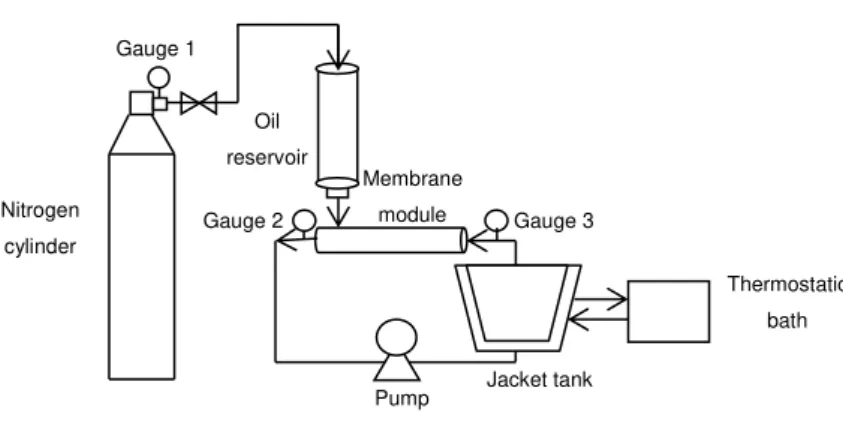
O/W emulsions were prepared in direct emulsification cross-flow system, using integral asymmetric tubular α-Al2O3 membrane. The system houses tubular membranes of 68 mm inner diameter and 250 mm in length. The system separated the inside and outside of the membrane, allowing the dispersed phase to be pressurized through the membrane from the outside of the tube using nitrogen gas, while the continuous phase flowed inside the membrane in a recirculating fashion using a piston pump, as shown in Figure 10. The pressure in the system was monitored by gauges installed on the inlet and outlet of the membrane module and on the nitrogen cylinder on the permeate side, in order to accurately control transmembrane pressure. Transmembrane pressure was defined as the pressure applied to the dispersed phase, measured at the dispersed phase tank, minus the average of the input and output pressures of the continuous phase through the membrane module. Dispersed phase flux was calculated using volume and time data according to Eq 4, but this time, v was not the permeate volume, but the dispersed phase volume (m3) that passed through the membrane.
Figure 10. Schematic representation of the direct membrane emulsification
A 23 central composite design was used to perform the tests for the direct membrane emulsification of linseed oil, considering three factors (independent variables): continuous phase velocity (cross flow velocity), transmembrane pressure and concentration of the surfactant Tween 20. Three levels of each variable were chosen for the trials, including four replicates of the central point, giving a total of 12 combinations (Table 3). The following polynomial equation was fitted to data:
y = 0 + 1x1 + 2x2 + 3x3 + 11x1 2
+ 22x2 2
+ 33x3 2
+ 12x1x2 + 13x1x3+ 23x2x3
Pump Nitrogen
cylinder
Oil reservoir
cylinder Membrane module
Thermostatic bath
Jacket tank Gauge 1
23 Where n are constant regression coefficients; y is the response and x1, x2 and x3 are the coded independent variables (continuous phase velocity, pressure and surfactant concentration, respectively).
The responses evaluated in the experimental design were transmembrane flux; stability, in terms of % of separation; particle size, in terms of Sauter mean diameter (surface mean diameter) and De Brouckere mean diameter (volume mean diameter); and droplet size distribution (span).
The boundary conditions of the experiment design (Table 3) were determined in preliminary tests (data not shown).
The tests were performed randomly with 4 replicates in the central point, summarizing a total of 12 trials and named as CFME.
Table 3 . Codified in dep end ent va ria bles
Code
Pressure
(bar)
Velocity
(m s
-1)
Tween 20
concentration
(%w/w)
-1
1.5
3.0
1.0
0
3.0
5.5
2.0
1
4.5
8.0
3.0
After each process, the module was cleaned by circulation with water to remove the excess of oil and disassembled to clean the parts separately. The membrane was imersed in a bath with controlled temperature of 70oC for one hour. Then, it was subjected to ultrasonication for 2 hours, since ladisavl evic et al. (2004) showed that
this treatment was essential to completely clean the
membrane pores. Both cleaning steps were performed with a solution with concentration of 0.2 % of a commercial enzimatic detergent KOCHKLEEN ® UC III (Koch Membrane Systems, USA).The hydraulic permeability was measured before each process in order to asssure that the cleaning procedure was efficient and that the membrane was in the same conditions. This parameter was calculated from Darcy’s equation.
(6)
Where Jv is the water flux, ΔPTM is the transmembrane pressure and LP is the hydraulic permeability.
3.3 Membrane characterization
3.3.1 Scanning electron microscopy (SEM)