Experimental study of RC beams strengthened for
bending by reinforced grout layer and connectors
Estudo experimental em vigas de CA reforçadas
à flexão por encamisamento e conectores
a Instituto Federal de Educação, Ciência e Tecnologia de Minas Gerais, Departamento de Engenharia Civil, Piumhi, MG, Brasil; b Universidade Federal de Uberlândia, Faculdade de Engenharia Civil, Uberlândia, MG, Brasil.
Received: 01 Nov 2016 • Accepted: 25 Aug 2017 • Available Online:
J. H. CANAVAL a
junior.canaval@ifmg.edu.br
T. J. DA SILVA b
tjdsilva@gmail.com
A. C. SANTOS b
acds.pir@gmail.com
Abstract
Resumo
This work is based on an experimental investigation of reinforced concrete beams strengthened to flexure for wrapping applying a type of metallic
connector in the bond substrate/groute. The experimental program consisted of 5 beams used for reference (without strengthening), 5 beams reinforced with surface brushed texture substrate and 5 beams with metal connectors bonded to the substrate. The beams were submitted to
four-point load bending test. Initially with a partial loading, executed the strengthening and were finally tested until the break. The strengthening was made up by the increase by graute, on the sides and bottom of the beam and reinforcing. The applied force, the displacement, deformations in steel and in concrete were measured. The reference beams failure by flexing with the calculated charges. The bending strengthening proved efficient, increasing the bearing capacity in 44% and the failure was by shear in the stretch without strengthening. Beams with connectors the
increase was higher.
Keywords: reforço estrutural, estruturas de concreto armado, interface concreto-graute, conectores.
Este trabalho é relativo a uma investigação experimental sobre reforço à flexão de vigas de concreto armado por encamisamento aplicando-se
um tipo de conector metálico na ligação substrato/concreto novo. O programa experimental foi constituído de 5 vigas utilizadas para referência (sem reforço), 5 vigas reforçadas com superfície do substrato de textura escovada e 5 vigas com conectores metálicos colados no substrato.
A aplicação de força foi em dois pontos, inicialmente com um carregamento parcial, executou-se o reforço e finalmente foram ensaiadas até a
ruptura. O reforço foi composto pelo acréscimo parcial, por graute, nas laterais e fundo da viga e armaduras. A força aplicada, os deslocamentos,
as deformações no aço e no concreto foram medidas. As vigas de referência romperam por flexão com cargas próximas às calculadas. O reforço à flexão mostrou-se eficiente, elevando a capacidade portante em 44 % e a ruptura foi por cisalhamento no trecho sem reforço. Nas vigas com
conectores o aumento foi superior.
1. Introduction
Historically, and may still be, the reality of constructions in Brazil
shows that the number of structures in reinforced concrete
susceptible to rehabilitation increases as they age. When a structure is no longer able to adequately meet its functions, it is necessary to rehabilitate it, that is, to make it capable of satisfying society’s demand, at the original or higher level, both from the point of view of durability and resistance (FIB [1]). Often structural elements are damaged by misuse, accident or lack of maintenance, making structural recovery services a common task.
The need for structural strengthening arises when a given structural
element or structure is no longer able to withstand the applicant’s efforts. It can also be used when there are changes in the use of
the building that increase the load and changes in the structural
system [2]), due to design and / or construction errors, materials without quality, absence of periodic maintenance, intrinsic and
extrinsic thermal variations to concrete and accidents, such as
shocks, earthquakes, fires, explosions (Simões [3]). However, for the case of recovery or strengthening, there are complex variables in this type of intervention.
One of the variables is the connection between elements shaped
at different ages, being one of the factors that can have serious consequences when not properly analyzed and projected. This
linkage, between substrate and new concrete, is determinant for the
performance, durability and effectiveness of all structural recovery
or strengthening services, therefore it is of fundamental importance
to know its influence. The recovery or strengthening project in Brazil
does not have standards, according to the research carried out in
the ABNT catalog. In addition, recovery and reinforcement services
result in high cost and skilled labor is needed.
In the preparation of the strengthening project, the existing structure must be evaluated in advance, which involves the available information on design and construction, inspection and
analysis of safety conditions.
It is essential, in strengthening services, the unloading of all weight
that can be removed from the structure without affecting it, in
order to guarantee the stress transmission to the material used
in the reinforcement process. In order to guarantee the efficiency
of the reinforcement process, the materials used must have good
durability, low permeability, good strength, good adhesion to concrete and steel, low shrinkage, good workability and compatible properties with concrete and steel (Simões [3]). It is also necessary to know the deformability properties, which includes retraction, deformation modulus, thermal expansion coefficient and Poisson’s coefficient. Differential deformations between substrate and new concrete can cause stresses at the bond interface, affecting reinforcement durability and stress transferability (Reis [2]). There are several types of flexural strengthening of beams. Some types also provide strengthening against failure by shearing. Strengthening by bonding steel sheets is a technique applied in cases of deficiency in existing reinforcement, but when structural dimensions and concrete quality are adequate. Strengthening by fiber reinforced polymers in general is carried out in elements that
require additions in the tension region, but are also used for shear
or in columns. There are catalogs and books about this type of
strengthening , generally following international standards (ACI [4] and FIB [5]).
The strengthening by post-tensioning systems of reinforced concrete beams basically consists of the insertion of requests contrary to those caused by the loads acting on the structure,
reducing the deformations and arrows. The introduction of
opposing forces can be promoted by the use of struts, wires or
rods, being able to increase the strength of the structural element
through a vertical component contrary to those caused by external and permanent loads. To this end, diverter devices may be placed between the tendons and the structure to deflect the
tendon as required. These devices and their attachment zones have to be designed to transfer the corresponding design actions
(FIB [1]). The strengthening by external post-tensioning systems can also reduce cracks and arrow openings, redistribute efforts in beam spans, increase the load bearing capacity of the beams and supply the deficiency of internal reinforcement.
The strength by casing, which was the type used in this research, is applied by adding reinforced concrete / mortar to the elements
to be rehabilitated, increasing the cross section or replacing
the deteriorated material. Similar tests were performed by Altun [6]. The strength beams are composite pieces, formed by the connection of two concretes of different ages, which have different
characteristics. There is an interface between these concretes, or
between concrete and grout, which is responsible for the quality of strengthening, promoted by adherence. Such adhesion is necessary to prevent sliding between the parts so that the part works monolithically.
The calculation of the beams strengthening, in the case of cladding
can be done based on NBR 6118 [7], considering the stress and deformations existing before it (FIB [1]).
Concrete-concrete bonds, molded at different ages, should be
considered as the transfer of stresses through the interfaces, whose main objective is to withstand the shearing stresses. The
adhesion between substrate and new concrete is necessary
to guarantee the joint behavior of the original part and the strengthening, in order to approach the behavior of a monolithic
part (ACI [8]). The treatment of the bonding surface is fundamental to obtain a satisfactory bond between the substrate and the new concrete, in order to obtain better adherence conditions (FIB [1]).
The bonding surface must be rough, free from dust, grease or oil and should be applied for removal of the cement laitance. Tests
carried out by Cheong and Macalevey [9] verified the influence of the type of anchorage, the form of anchorage and the amount and type of anchorage of the stirrups.
The main factors that influencing at the interface resistance are
concrete strength, contact surface adhesion, contact surface
roughness, shearing keys, transversal reinforcement and load type. The mechanisms of stress transfer at the interface can be by frictional, mechanical actions and transversal reinforcement that crosses the interface, called connectors (FIB [1]). The use
of connectors in the bonding interface promotes increased resistance to shearing stresses, and the adoption of connectors across the interface between substrate and new concrete is
The present work aims to verify the influence of steel connectors,
positioned between the interface surface between substrate and
grout, in the flexural strengthening of beams produced by the
increase of the cross section and addition of reinforcements in the tension region.
2. Materials and experimental program
2.1 Experimental program
The experimental program aimed to evaluate the influence of steel
connectors, positioned to the concrete-grout interface surface,
designated in this work as interface, in the flexural strengthening of beams produced by the increase of cross section and additional
reinforcement. The bonding surface interfaces were smooth without and with steel connectors being used. The contact surfaces were brushed in order to remove the laitance from the cement and increase the roughness. The connectors were fabricated with 10
mm diameter RC 50 steel bar rests, that is, easy to manufacture. It should be noted that the study has aspects that differ from the existing majority. The first is that in most of the studies the reinforcement is due to insufficient armor, while reinforcement
will be carried out for the tensioned and compressed region. Another important aspect is the approximation of the tests to a real situation: in practice one can make a small relief in the actions and the reinforcement is executed with the remaining action acting on
the beam and finally it is released for the total action superior to
that of the initial design, so it will be simulated in the test.
The experimental program consists of 15 beams distributed in
three test series, each series consisting of 5 beams, identified from 1 to 5. A series of 5 beams used for reference (VRef), without any
reinforcement, 5 reinforced beams with smooth interface substrate (VL) and 5 reinforced beams with substrate surface containing bonded steel connectors (VC).
The reference beams, called VRef, were 200 cm long, span from
180 cm, rectangular cross section with 12 cm wide by 22 cm high
and 3 cm cover.
The reinforcement on the beams with smooth interface surface,
with and without connectors, was performed by adding SikaGrout®
250 grout, in the sides and bottom section in a length of 140 cm.
The steel connectors were positioned vertically using the Sikadur® Epoxy, spaced every 10 cm. The bonding of the connectors
occurred with the beam in pre-loading condition.
Self-compacting concrete, with a compressive strength of 20 MPa, was used in the reference beams. For the reinforcement of the
reference beams, 2ø12,5 mm were used in the bottom longitudinal reinforcement and 2ø5 mm for the upper longitudinal reinforcement,
that had the sole function of carrying of stirrups. The stirrups were ø5 mm, spaced every 10 cm. The beams were subjected to four
points bending test, distant of 60 cm of the supports.
2.2 Calculations for the reference beam
The design of the beams was done in such a way that the “x” value was 40% of the useful height of the beam and that failure by tension in the flexion, with yield stress of the longitudinal reinforcement
and crushing of the compressed concrete. To determine the useful height, it was considered that the longitudinal reinforcement would have a diameter of 12.5 mm, the stirrups 5 mm and the cover of 3.0 cm, resulting in a useful height of 17.875 cm. The bending moment
of calculation, for these conditions, supported by the beam was
obtained through Equation 1.
(1)
Where: Md is the design bending moment, fcd is the design value of cylinder compressive strength of concrete , bw is the breadth of web, x is depth of compression zone and dd is the effective depth
to main tension reinforcement.
Adopting the weighting coefficient of the concrete strength of 1.4, resulted in a bending moment of 12.51 kN × m. The necessary flexural longitudinal reinforcement was obtained by applying
Equation 2, which resulted in a steel area of 1.92 cm².
(2)
Where: As is the area of reinforcement, fyd = 43.48 kN / cm² is the design yield strength of reinforcing steel in tension.
With the adopted tension reinforcement bars of 2ø12,5 mm, the “x”
Figure 1
change from 0.4 × d to 0.513 × d, increasing the bending moment of calculation to 15.16 kN × m. In order to reach this calculation bending moment, considering that the beam weight itself produces
a bending moment of calculation of 0.33 kN × m, the total Fd load
to be applied is 49.45 kN. This value was obtained considering
the coefficients of NBR 8681 [9], but as the load will be controlled and with a small variation a smaller coefficient was adopted so the design load considered 100% will be 42.5 kN.
Figure 1 shows the stress and strain states of the reference beam section with 100% and 80% of the permanent load acting on the beams. The stress in the concrete for the section submitted to 80% of the load was obtained according to item 8.2.10.1 of NBR 6118 [7]. The transversal reinforcement design was done by adopting the calculation model I of NBR 6118 [7], which allows compression
diagonals inclined to 45 ° in relation to the longitudinal axis of the structural element and that the portion of shearing force
resisted by mechanisms complementary to the lattice model has
a constant value. The shear reinforcement was obtained through Equation 3.
(3)
Where: Asw: area of shear reinforcement; Vsw: resistance of
reinforcement to shear force; dd: effective depth to main tension
reinforcement; fywd: design yield strength of stirrups steel in tension. Considering the calculation force in the design of 49.45 kN and the self weight, the shearing produced will be 25.56 kN. The portion of
shearing force absorbed by mechanisms complementary to that
of the lattice (Vc0) is 14.22 kN. Using the stirrups of ø5.0 mm, the calculated area of shear reinforcement is 1.615 cm2 / m, therefore, ø5.0 mm stirrups spaced 24 cm. Due to the maximum spacing
allowed, ø5.0 mm stirrups spaced 10 cm, was used. The use of these stirrups allows the beam to be subjected to a shearing of up to 41.69 kN, being 14.22 kN of the Vc0 and 27.47 kN of the resistance of reinforcement (Vsw). The total force Fd, discounted
from the calculated shear produced by the self weight of 0.83 kN, may be 81.72 kN applied to the beam, i.e., 40.86 kN per point.
2.3 Calculations for the reinforced beam
The reference beam executed has its ability to resist flexural
moment at 15.16 kN × m and 81.72 kN for shear. As the
reinforcement will not be for shearing, it was initially calculated
for the applied calculation load of 81.72 kN, thus a total bending moment of calculation of 24.90 kN × m.
The original beam section, after having reduced the weight, has not behavior at Ultimate Limit State (ULS), and the new position of
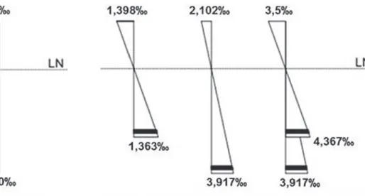
the “x” was obtained through the equations of static equilibrium and deformations. In Figure 2, deformation conditions of the section of the original beam with load Fd = 49.45 kN (ULS) or Fk = 35.32 kN and
for the maximum design load after the reinforcement (87.70 kN) are
shown, indicating that the failure is likely to occur by shearing. The tension in the concrete for the section submitted to 80% of the design load (34 kN) was obtained according to item 8.2.10.1 of NBR 6118 [7].
The tension in the grout was obtained according to item 8.2.10.1 of
NBR 6118 [7], adopting behavior like concrete, as it is cementitious material. A reduction factor of 0.85 (Rüsch effect) was adopted to
obtain the grout tension due to the lack of knowledge about this
effect in the material.
From the static equilibrium equations, considering grout with a compressive strength of 50 MPa, a steel area of 2,122 cm² was obtained for reinforcement. Due to the need for bonding of strain gauges on the bars, it was decided to place 2ø12.5 mm. With this
steel reinforcement and grout, the area will have a durable bending moment of 37.16 kN × m. To achieve this bending moment an applied characteristic load of 87.70 kN is required, indicating that
the failure to occur by shearing.
Therefore, the reinforcements were 2ø12.5 mm in the lower longitudinal part and 2 ø 5.0 mm in the upper longitudinal part.
The transverse reinforcement were ø5.0 mm, spaced every 10 cm.
Figure 2
The values presented for the resistant bending moments contemplate
the safety criteria used by the norms and consider that there will be
the perfect connection between the concrete and the grout. In this
way, the values obtained in the tests are expected to be higher. The geometry and reinforcement information of the strengthened beams are shown in Figure 3.
2.4 Steel connectors
The steel connectors were placed in view of a possible partial failure in the bond between concrete and grout. Simple connectors were designed and can be made with common construction steel bars.
Thus, they were produced using steel bars of ø10 mm, having 15
cm of length, being in part of the surface were removed area of the
doughs for bonding in the substrate. They were positioned to the partially loaded beams and, later, the reinforcing, the formworks and the grout were placed (Figure 4).
Figure 3
Beam geometry and frame information
Figure 4
Details of the connectors
a) Connectors (front)
b) Connectors positioned in a10 cm spacing
Figure 5
Schematic of the localization of the extensometers
a) Extensometers attached to the central part
of the longitudinal tension reinforcement of
the original beam
c) Extensometers attached in the central part of
the longitudinal tension reinforcement
b) Extensometers attached to the sides
of the original beam (region tensioned
and compressed)
d) Extensometers attached on the sides
of the reinforcement (region tensioned
2.5 Strain gage position
The strain measure in the steel were obtained through uniaxial
resistance strain gages with a length of 0.250 “. In the concrete were uniaxial with length of 1,000 “, both with gage resistance of
120 Ohms. A linear displacement measuring device, was used, and the structural behavior of the beams during the tests was recorded
through a data acquisition system. Previously, the strain gages were fixed in the reinforcement and in the concrete after cast of the
reference beam. After the partial loading and strengthening, the
strain were fixed in the grout, as indicated in Figure 5.
2.6 Force application program and results
The experimental system was four point bending test, distance load-supports of 60 cm, according to Figure 6. The beams,
before being reinforced, were loaded with total design load
until the stabilization of the displacement. For the strengthening service, the beams were partially discharged, remaining 80% of the load (34 kN), considering a 20% relief of the accidental load
for the structure.
The strengthened beams were submitted to the total design load and later until the failure, after completing the strengthening and waiting 24 hours to achieve resistance of the grout.
3. Results and discussions
The compressive strength of concrete at 7 days, 28 days, essay’s day and the modulus of elasticity, obtained according to NBR 5739 [11] and NBR 8522 [12], respectively, are shown in Table 1.
The tests of the steel bars were carried out according to NBR 7480
[13]. The results obtained are shown in Table 2.
3.1 Reference beams
The compressive strength of concrete was 22.78 MPa and modulus of elasticity of 27.04 GPa, at the time of the tests of the reference beams. It is verified that the modulus of elasticity reached the value compatible with the estimated by the NBR 6118 [7] equation. Initial crack due to flexion occurred in 4 reference beams (V2Ref to
V5Ref) and V1Ref presented initial shearing crack. All the beams
failed due to flexion. In the Figure 7 are showed the characteristic
cracks in the center of the reference beams. Table 3 shows the results obtained during the tests of the reference beams.
The structural behavior of the reference beams during the tests
have made it possible to verify that:
n The first cracks in the beams appeared with an average load of
65.14 kN, except the V4Ref that obtained the first crack, due to flexion, with a load of 54.7 kN. Considering all the loads when the first crack appeared, the average load was 63.05 kN.
n The failure loads of the beams were close, obtaining an average failure load of 72.15 kN and a standard deviation of 1,712 kN.
The coefficient of variation - CoV of 2.37% - indicates uniformity
Figure 6
Test pattern of the beams
a)
Beams without reinforcement
b)
Reinforced beams
Table 1
Concrete information for the beams
Age (days)
Strenght to average-compression
(MPa)
Standard deviation
(MPa)
Coefficient of variation
%
Average modulus of elasticity
(GPa)
Standard variation
(GPa)
Coefficient of variation
%
7 12,85 1,56 12,14 – – –
28 21,99 0,04 0,18 19,89 1,03 5,18
Table 2
Mechanical properties of steel
Diameter (mm)
Yield stress (MPa)
Average failure tension
(MPa)
Average stretching
in 10ø
in the behavior of the beams, therefore it can be considered
that, for comparative effect, the results are consistent.
n Considering the concrete strength of 22.78 MPa, obtained at
the test date, the calculated failure load in which the coefficients
equal to 1 were considered, increases from 49.45 kN to 73.83 kN, which was close of the average failure load obtained during the tests (72.15 kN).
n Analyzing the load-displacement ratio, it was possible to
verify that the vertical displacements for all the tests were very close, with an average of 6.16 mm, when the applied load of the design was analyzed, being the standard deviation of the displacements obtained for 100% of the load of applied equal to 0.478 mm, resulting in a CoV of 7.77%.
At disruption, vertical displacements averaged 13.92 mm
and CoV was 16.79%.
n The average steel strain obtained for 100% of the load was
1.878 ‰ and for 80% of the load was 1.538 ‰. The calculated deformation considering 100% of the design load was 3,333 ‰ and for 80% of the design load was 1.363 ‰.
n The average strain on the compressed face of the concrete
obtained for 100% of the load was 0.7146 ‰ and for 80% of the load was 0.6359 ‰. The strain considered for 100% of the design load was 3.5 ‰ and for 80% of the design load
was 1.398 ‰.
n Considering all the reference beams, the average strain in the compressed face of concrete obtained at the instant of failure
was 1,764 ‰. The V1Ref suffered a much greater strain, when
compared to the others, presenting deformation of 2,649 ‰,
being the only reference beam that cracked due to shearing.
3.2 Reinforced beams without connectors
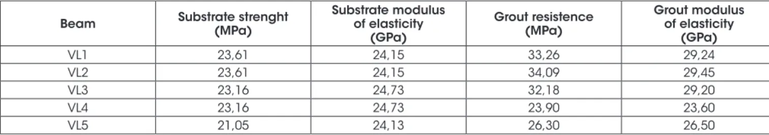
At the time of the tests of the beams without connectors, the substrate concrete and the grout had the characteristics described in Table 4.
Due to the time between the tests of the beams being approximately 30 hours, 4 cylindrical specimens were used to determine the compressive strength and modulus of elasticity of the concrete
Figure 7
View of the central part of the reference beams broken by flexion
a)
V1Ref
b)
V2Ref
d)
V4Ref
c)
V3Ref
e)
V5Ref
Table 3
Results of reference beams
Beams 1ª crack(kN) Type of crack
Displacement 100% load
(mm)
Failure
Displacement (mm)
Load (kN)
Average load (kN)
Standard deviation
(kN)
Coefficient of variation
%
V1Ref 65,00 Shearing 6,16 17,95 74,36
72,15 1,712 2,37
V2Ref 68,27 Flexion 6,32 12,32 71,87
V3Ref 62,30 Flexion 6,02 13,75 73,34
V4Ref 54,70 Flexion 6,81 12,31 70,08
substrate for each 2 beams. For the grout, the determination of the compressive strength and modulus of elasticity was performed for
each beam tested. All these tests followed the procedures of the
standards of NBR 5739 [11] and NBR 8522 [12], respectively.
Of the 5 beams with smooth surface without tested connectors,
only VL1 presented flexural cracking during preloading, and the appearance of the crack at 44.98 kN. Figure 8 shows the
characteristic cracks in reinforced beams without connectors. Table 5 shows the results of the displacement, the failure loads,
and the types of cracks obtained for the smooth interface beams
without connectors.
Analyzing the results obtained during the tests it is possible to verify that:
n The first cracks, after the beams reinforcement service, appeared with a mean load of 68.60 kN, standard deviation of
13.61 kN (CoV = 19.84%).
n None of the reinforced beams showed cracking due to
grout’s tension.
n The average load of the strengthened beams with smooth interface without connectors was 104.08 kN, with a standard
deviation of 8.77 kN (CoV = 8.37%).
n Analyzing the displacement of the beams at the failure, it was
possible to verify that the values were very close, being 12.9
mm the average obtained for the displacement, in which it
obtained a standard deviation of 1.52 mm (CoV of 11.78%).
n All the beams had pre-cracking due to shear and were
subjected to failure by shearing of the substrate, varying due to
crack and grout detachment.
n The beam VL4 showed a significant deviation in the strain
analisys in the longitudinal tension reinforcement, but after this
reading it returned to a number closer to the previous ones. The same beam (VL4) also presented a reading that indicated that the upper face of the concrete of the substrate after the reinforcement service was alleviated, generating a smaller strain for the higher tensions.
n The average strain in the longitudinal tension reinforcement of the substrate at the moment of failure was 2.089 ‰, with a
standard deviation of 0.535 ‰ (CoV = 25.61%).
n The average strain in the compressed face of the grout obtained at the moment of failure was of 0.449 ‰, presenting a standard deviation of 0.130 ‰ and for the longitudinal tensile reinforcement of the reinforcement the average strain obtained at the moment of failure was of 1.317 ‰. It should be noted that the deformation of VL1, VL2 and VL5 was considered for the calculation of the mean strain for the tension reinforcement, considering that for the other beams the data acquisition did not record the values for these deformations. The VL1 presented a lower deformation value for both the grout and the tension reinforcement, when compared to the others, presenting deformation of 0.246 ‰ for the grout and 1,000 ‰ for the reinforcement. Therefore, the reinforcement for this beam was the one that least supported the increase of load, and the failure occurred with the lowest load
Table 4
Material information at the time of the test – beams with smooth interface without connectors
Beam Substrate strenght (MPa)
Substrate modulus of elasticity
(GPa)
Grout resistence (MPa)
Grout modulus of elasticity
(GPa)
VL1 23,61 24,15 33,26 29,24
VL2 23,61 24,15 34,09 29,45
VL3 23,16 24,73 32,18 29,20
VL4 23,16 24,73 23,90 23,60
VL5 21,05 24,13 26,30 26,50
Table 5
Results of beams with smooth interface without connectors
Beams
Load 1st
crack after strengthening
(kN)/type of failure
Arrow (mm)
Failure load
(kN) Failure type 80% load 100% load Failure
VL1 85,61 / shearing 7,00 7,10 10,87 90,87 Substrate shearing /
grout detachment
VL2 70,64 / shearing 6,32 6,84 13,37 102,03 Substrate shearing / grout
rupture and detachment
VL3 53,80 / shearing 6,64 7,23 12,96 113,01 Substrate shearing / grout
rupture and detachment
VL4 76,99 / shearing 6,80 6,98 15,03 103,42 Substrate shearing /
grout rupture
VL5 56,00 / shearing 6,38 7,21 12,27 111,09 Substrate shearing / grout
applied in relation to the other strengthened beams with surface of the smooth interface.
The strain values for reinforced beams with smooth interface without connectors are listed in Table 6.
3.3 Strengthened beams with connectors
In performing the tests of the beams with smooth interface surface with bonded steel connectors, the substrate concrete and the grout presented the characteristics described in Table 7.
The intervals between the beams tests were also approximately
30 hours, like beams without connectors. The compressive
strength and modulus of elasticity of the concrete substrate were determined. In the same way these characteristics were
determined to the grout, for each beam tested. These tests also
followed the procedures of the norms of NBR 5739 [11] and NBR 8522 [12], respectively.
Two beams with steel connectors, VC3 and VC5, showed flexural
cracks during preloading. The cracks appears when the loads
43.31 kN and 43.29 kN were applied, respectively. Figure 9 shows
the characteristic cracks in the beams reinforced with connectors. n The results of the displacement, failure loads and type of
failure obtained for the beams with bonded steel connectors
are presented in Table 8, and it can be verified that: The first
cracks, after the beams strengthening service, appeared with an application of average load of 76.37 kN, with a standard deviation of 4.69 kN, presenting for most of the beams tested values higher than the beams that did not have the steel
Figure 8
Details of VL3 after test
a)
Substrate crack due to shearing
c)
Grout rupture
e)
Final aspect of the beam
(le� side view)
f)
Final aspect of the beam
(right side view)
b)
Beam support crack due to shearing
connectors bonded. From this result it is possible to verify
that the bonded steel connector contributes, even with a small portion, to the shearing strength.
n None of the beams tested showed flexural cracks in the reinforcement.
n The average failure load of the strengthening beams with bonded steel connectors was 106.10 kN, with a standard deviation of 6.04 kN.
n Analyzing the displacement of the beams in the failure, it was
possible to verify that the values were close, being 12.82 mm
Table 6
Strains of the constituent elements of the beams at the moment of failure
Beams
Concrete substrate top surface
(‰)
Longitudinal tension steel of the subtrate
(‰)
Grout top surface (‰)
Longitudinal tension of reinforcement
(‰)
VL1 0,611 1,844 0,246 1,000
VL2 0,986 1,531 0,428 1,572
VL3 0,259 2,565 0,539 X
VL4 0,042 2,751 0,449 X
VL5 0,997 1,752 0,583 1,378
Table 7
Material information at the time of the test – beams with connectors
Beams Substrate strength (MPa)
Substrate modulus (GPa)
Grout strength (MPa)
Grout modulus (GPa)
VC1 21,05 24,13 27,90 23,80
VC2 24,07 22,76 23,27 26,37
VC3 24,07 22,76 21,68 25,21
VC4 23,00 22,94 16,94 24,85
VC5 23,00 22,94 23,72 26,99
Figure 9
Details of VC4 after test
a)
Grout rupture
Right support/right surface
d)
Grout rupture
Right support/le� surface
b)
Rupture by shearing
Right support/le� surface
e)
Beam rupture by shearing
Le� support/right surface
c)
Rupture by shearing
Right support/right surface
the average obtained for the displacement, in which it obtained
a standard deviation of 1.24 mm (CoV = 9.67%).
n All the beams, after the strengthed, had pre-cracking due to
shearing and suffered failure by shear of the substrate, varying
due to the rupture and the detachment of the grout.
The deformation values for the strengthening beams with bonded steel connectors are listed in Table 9.
n The VC1 beam showed strain on the upper face of the incoherent substrate concrete in relation to the others. It should
be noted that this value may have occurred due to failure of the constituent devices of the measurement system.
n The VC4 beam showed deformation in the upper face of the
concrete substrate of 2.003 ‰, a considerably higher value
when compared to the beams VC2, VC3 and VC5, but such deformation was possible considering the ULS deformations. n The average strain in the longitudinal steel tension of the
substrate at the instant of failure was 2.161 ‰, with a standard deviation of 0.295 ‰.
The average strain in the compressed face of the grout obtained at the instant of failure was 0,479 ‰, with a standard deviation of 0,096 ‰. The average deformation obtained at the failure instant was of 1,399 ‰ and standard deviation of 0.277 ‰ to longitudinal
tensile of the reinforcement. It should be noted that for the calculation of the mean strain for the tensile strengthening steel bars, the deformation of the VC2 was not considered due to the fact that the data referring to this information were not recorded. The
values presented and discussed for the failure load were different, indicating that the types of reinforcement influenced the results. For a more consistent analysis, the analysis of variance - ANOVA was
performed, between the results of the group of reference beams, the beams with surface of the smooth interface and the beams with surface of the smooth interface with bonded steel connectors, considering the failure load. Although several beams have cracked
due to shearing, the stiffness of the reinforced part may have influenced the stress distribution mechanisms, allowing the load variations to be verified. Table 10 shows the ANOVA values. It is verified that there is evidence that the type of reinforcement influenced the failure load, since F obtained was higher than Phytic and also, the P-value was less than 0,05.
4. Conclusions
The strengthening by casing using grout and reinforcing bars is a technique that allows to increase the maximum load capacity of the
Table 8
Results of the beams with positioned steel connectors
Beams
Load 1st
crack after reinforcement
(kN)/type of failure
Displacement (mm)
Failure load
(kN) Type of rupture 80% load 100% load Rupture
VC1 71,73 / Shear 5,84 6,52 12,28 106,44 Substrate shearing / grout
rupture and detachment
VC2 75,36 / Shear 5,41 6,22 11,57 106,75 Substrate shearing /
grout detachment
VC3 72,54 / Shear 8,05 8,08 13,86 97,05 Substrate shearing / grout
rupture and detachment
VC4 79,46 / Shear 7,05 7,36 14,42 114,09 Substrate shearing /
grout rupture
VC5 82,79 / Shear 6,33 6,42 11,97 106,16 Substrate shearing /grout detachment
Average failure load = 106,10 kN
Table 9
Deformations in the components of the beams at the moment of failure
Beams
Upper surface concrete/substrate
(‰)
Substrate longitudinal tension reinforcement
(‰)
Grout upper surface (‰)
Longitudinal tension reinforcement
(‰)
VC1 6,145 2,338 0,426 1,526
VC2 0,204 2,144 0,494 X
VC3 0,368 2,198 0,386 1,036
VC4 2,003 2,448 0,635 1,683
VC5 0,449 1,678 0,452 1,349
Table 10
Analysis of variance – single fator
Analysis in groups SQ gl MQ F P-value F Influence
VR,VL e VC 2723,92 2 1361,96 30,39 9,94E-05 4,256 Yes
SQ is the sum of the squares of all deviations from the mean of all observations (between and within the samples); gl is the degree of freedom; MQ is the quadratic mean (between and within the samples).
P-value is the probability that the null hypothesis is true. The significance level of the test was set at 0.05.
beams, being verified that there was an increase, in relation to the flexion, of 44.25% and 47.05% for smooth interface beams without and with steel connectors , respectively.
The calculation of the strength using the stress and strain states reached values close to those obtained during the test, when the
safety coefficients were not taken into account.
It should be noted that the beams could have reached higher
loading values if they had not failure by shearing of the substrate. For this reason it was considered that the maximum load capacity
was not higher because all the beams after the reinforcement
failed by shearing of the substrate.
The treatment of the surface, which consisted only in the removal of the layer of the cement dust, favored the adhesion when the
grout was applied as a reinforcement material.
It was possible to verify that the average displacements of the reinforced beams (without and with connectors) were very close. The steel connector contributed, although in a small part (2.8%), to
the shearing strength acting at the interface, being the limiting factor
the detachment of the concrete cover layer in which it was bonded.
It should be noted that the initial objective of the research was to
verify the possibility of using this type of connector, that is, without
the appearance of cuttings in the beams. This objective was
partially achieved and was promising.
5. Acknowledgments
The authors thank UFU - Federal University of Uberlandia for
providing structure for this work.
6. References
[1] FÉDÉRATION INTERNATIONALE DU BÉTON – FIB. Model
Code 2010. Switzerland, 2010. v. 1.
[2] REIS, A. P. A. Reforço de vigas de concreto armado por meio
de barras de aço adicionais ou chapas de aço e argamassa
de alto desempenho. Dissertação (Mestrado) – Escola de Engenharia de São Carlos, Universidade de São Paulo, 1998. [3] SIMÕES, M. L. F. Reforço à flexão de vigas de concreto
armado por encamisamento parcial. Dissertação (Mestrado) – Faculdade de Engenharia Civil, Universidade Federal do
Rio de Janeiro, 2007.
[4] AMERICAN CONCRETE INSTITUTE - ACI 440.2R-08 Guide for the design and construction of externally bonded FRP systems for strengthening concrete structures. Farmington Hills. MI-USA. 2008.
[5] FÉDÉRATION INTERNATIONALE DU BÉTON – FIB. FRP
reinforcement in RC structures. Technical Report. Bulletin 40. Switzerland, 2007
[6] ALTUN, F. An experimental study of the jacketed
reinforced-concrete beams under bending. In: Construction and
Building Materials. v.18, 2004. p.611-618.
[7] ASSOCIAÇÃO BRASILEIRA DE NORMAS TÉCNICAS. NBR 6118: Projeto de estruturas de concreto – Procedimento. Rio
de Janeiro: 2014.
[8] AMERICAN CONCRETE INSTITUTE. ACI 318: Building
Code Requirements for Structural Concrete and
Commentary. Farmington Hills, MI-USA, 2011.
[9] CHEONG, H. K.; MACALEVEY, N. Experimental behavior of
jacketed reinforced concrete beams. In: ASCE Journal of Structural Engineering. V.126, 2000. p.692-699.
[10] ASSOCIAÇÃO BRASILEIRA DE NORMAS TÉCNICAS. NBR 8681: Ações e segurança nas estruturas – Procedimento.
Rio de Janeiro: 2003.
[11] ______. NBR 5739: Concreto – Ensaios de compressão de
corpos-de-prova cilíndricos. Rio de Janeiro: 2007.
[12] ______. NBR 8522: Concreto - Determinação do módulo
estático de elasticidade à compressão. Rio de Janeiro: 2008.
[13] ______. NBR 7480: Aço destinado a armaduras para estruturas de concreto armado - Especificação. Rio de