Automatic Coverage Based Neighbour Estimation
System: A Cloud-Based Implementation
PAULO M. PINA 1, ANDRÉ F. GODINHO 1, DANIEL F. S. FERNANDES 1, DIOGO J. A. CLEMENTE 1, PEDRO SEBASTIÃO1, GABRIELA E. SOARES2, AND LÚCIO S. FERREIRA2,3,4, (Senior Member, IEEE)
1ISCTE-Instituto Universitário de Lisboa/IT–Instituto de Telecomunicações, 1649-026 Lisbon, Portugal 2Multivision - Consultoria, 1600-196 Lisbon, Portugal
3INESC-ID/ISTEC, 1750-142 Lisbon, Portugal
4COPELABS/Universidade Lusófona, 1749-024 Lisbon, Portugal
Corresponding author: Paulo M. Pina (pvmpa@iscte-iul.pt)
This work was supported in part by the OptiNET-5G Project, co-funded by Centro2020, Portugal2020, European Union under Project 023304.
ABSTRACT Over the years, mobile networks have grown exponentially due to rising demand. These
networks mix different types of cells, which makes manual configuration difficult, costly and tedious. Furthermore, inefficiencies stemming from these problems can cause problems in Handover performance, since a mobile device may not always connect to the optimal cell upon switching from one to the other, potentially harming service quality and increasing Operational Costs (OPEX). Existing solutions, like Automatic Neighbour Relations (ANR), while they are valuable in estimating the best neighbouring cells through the rate of successful Handovers, fail to take into account topological coverage factors and fictional cells, therefore inefficiencies lie hidden and it isn’t suited to calculate relations between planned cells and active cells. In this article, a proposal of a cloud-based, on-demand automatic coverage based neighbour estimation system is proposed, which utilises topological signal coverage data from each cell provided by the network’s operations support system, in order to mitigate the aforementioned issues and provide a reliable and convenient coverage analysis paradigm.
INDEX TERMS cloud computing, self-organising networks, self-optimising, self-configuration, neighbour relations, telecommunications
I. INTRODUCTION
A. MOTIVATION
Every mobile network presents multiple inter-connected cells that provide service to a variety of user equipment (UE). These cells have limited range, and once a UE is outside one’s range, the cell cannot provide service to it reliably. In that case, the UE should be able to connect to another cell to continue its service use without much interruption; this phenomenon is called Handover (HO). But, how does a UE know which cell to change to? While there are ways to blindingly search for whatever potentially valid signal that it can in order to resume a connection, those ways are not very efficient and could probably be dangerous in certain scenarios, such as accidentally connecting to dysfunctional cells, and therefore are sparsely used. Matters become more
The associate editor coordinating the review of this manuscript and approving it for publication was Parul Garg.
complex in the domain of heterogeneous networks (HetNets), which mix cells of varying frequencies, technologies and sizes on the same networks for various objectives.
A more sophisticated manner to handle proper Handovers is to maintain Neighbour Cell Lists (NCLs) in a cell’s database and provide them to the connected UEs so that they know who they should Handover to. The problem then becomes ‘‘how should these NCLs be built?’’. This is the motivation for the present work, which addresses NCL construction.
B. LITERATURE REVIEW
Several works pertaining to the automated creation and/or optimisation of NCLs, especially in the context of Long Term Evolution (LTE) heterogeneous networks (HetNets), were created over the decade of 2010. Many showed positive results in several areas, such as improved Handover (HO)
performance, reduction of system overhead and improved User Equipment (UE) battery life. Several such advances were made very early in the decade.
A proposal of an automated NCL optimisation method to replace manual methods was made by Nguyen and Claussen [1]; its main concern was about the extra system overhead from iterating over excessively long NCLs, causing calls to drop due to HO delays. It involved live measurements from UEs to self-configure an initial NCL, which would be continuously self-optimised during normal operation. Usage of this algorithm required some long-term investment, which would pay off either way: around over 6000 live measure-ments later, the handover target searching success rate with 10 or more neighbour cells would reach a success rate of about 99%. This work helped prove that the automation of NCL optimisation definitely has a place in network plan-ning and long-term network maintenance, and compared to a manual solution it can potentially reduce operational costs (OPEX), however, it only utilises measurements from UEs; furthermore, it’s dependant on values that are mostly useful in 2G and 3G technologies, which could make its potential adaptation to 4G or 5G costly.
That isn’t the only optimisation method that relies on user measurements. In fact, a proposal by Razavi et al. (which also involved H. Claussen) [2] utilised measurements that were prompted by BSs for UEs to execute and report back. These measurements could either be made to a specific list of cells or to every cell in the UE’s then-current NCL. This example had special care in preventing issues with HOs, since NCLs could only contain cells that the beholder could perform a HO to quickly, and they also required the Pri-mary Scrambling Codes (PSC) of every small cell, because their signal strength increased rapidly within their vicinity. A simulation was made on a 3G network in Berlin, which reported improvements in HO success rate and UE battery life. This method is unfortunately limited to existing NCLs, limited to 3G due to its dependency on PSCs, and could compromise an UE’s battery life through its consistent need for measurements.
Technologies from previous generations weren’t ignored. In 2013, a patent for the functionality of an agnostic NCL sys-tem was filed by Maida et al. [3], tested primarily in GSM 2G networks, and worked in a similar manner to LTE Automatic Neighbour Relation (ANR) systems: two base stations must detect and save each others’ signal, must check both cells for HOs from either side and then compute a weighing param-eter by agglomerating those two components to dparam-etermine HO Priority for each one’s neighbour relation. This, again, requires a fully functional network for that communication to take place.
On the other hand, attempts at virtualising network func-tions for 5G ANR systems have been made, for example, in a proposal by Shin and Kim [4]. Since the ultra-high frequencies that will be used by that technology don’t allow cells to reach very far, many nodes will be required in order to cover a large area as a consequence, which increases the
number of NCLs and their size. Simultaneous HOs were recognised as problematic, and measurements were made on the additional resources that were consumed and unoptimised NCL latencies. The proposal focused on utilising a central, common computer in order to create modifiable resource assignments, alongside running Evolved-UMTS Terrestrial Radio Access Network (E-UTRAN) NodeB (eNB) instances in data centres. With all of this, ANR was able to respond efficiently to network adaptations, with good resource man-agement and HO performance, though it’s still based on the same principles of ANR: the use of established and evolving HO statistics, which require a fully functioning network.
Another proposal, but this time only for the initial configu-ration of a NCL, was created by Kim et al. [5], which focused on eNB scanning to generate initial NCLs. It operated on the principle that an ideal NCL should only contain neighbourly relations where all related cells are overlapping each other in some manner in order to form an uninterrupted HO region. Adjacent cells would report Signal to Interference Noise Ratio (SINR) values to other cells in order to compare to a defined threshold to determine whether or not they can be a valid neighbour relation. The definition of this threshold depended on the size of the cell being scrutinised, being low if it’s a macro cell or being high if it’s a pico cell. The generated NCL managed to reflect the real radio environment, and its size varied depending on how large the SINR thresholds were: high SINR thresholds generated relatively small NCLs, reducing system overhead but increasing the likelihood of HO delays due to a lack of information, while low SINR thresholds would generate more extensive NCLs, reducing potential HO delays while increasing system overhead. The simplicity of such NCL creation protocols were, and still are highly pertinent today for HetNets.
HetNets are inherently complex, as the usage of Intra-Radio Access Technologies (Intra-RATs) and cell split-ting (division of macro cells into smaller, low-powered cells to increase capacity in congested areas) require sophisticated frequency allocation methods in order to manage loads and potential overlapping issues. An analysis of that prospect was made by Lei et al. [6], which boiled down three approaches to frequency resource allocation in HetNets:
1) Co-channel allocation: all cells in a HetNet share the same frequency band;
2) Orthogonal frequency allocation: macro cells and local cells are assigned different frequency bands, having no overlap between each other;
3) Overlapped frequency allocation: partial frequency overlap between macro cells and local cells, for exam-ple, local cells using all of the available frequency resource while macro cells use only part of it.
An evaluation of downlink data channel system capacity was made, revealing that the Overlapped frequency allocation method had the best results while the Orthogonal method had the worst results.
In order to have a more realistic notion of how user mobility affects HO performance in multi-tier HetNets,
Sadr and Adve [7] made an analysis of irregular networks (HetNets with randomly scattered small cells) by deriving the probability of cell coverage through the received SINR distribution and HO rate for an UE in two cases: one if the user is stationary (a HO did not happen) and another if the user is mobile (a HO most certainly happened). A simulation confirmed that when the user is mobile and the system is sensitive to HOs, the optimal tier association and probability of coverage depend on the user’s speed. This suggests that a bias factor dependent on speed can adjust an UE’s tier association to improve the system’s performance.
Femtocells are so small, that they may cause unnecessary HOs. Further research on HO performance in femtocell envi-ronments was made by Amirrudin et al. [8] in 2017, with a proposal for a HO prediction algorithm, which provided better performance than standard algorithms with a consis-tent number of HOs and without predicting any unnecessary HOs.
The mass usage of heterogeneous networks and their expo-nential growth make configuration, optimisation and main-tenance difficult for network operators, which prompts the usage of Self-organising Network (SON) techniques in three separate categories: self-configuration, self-optimisation and self-healing. Furthermore, constant changes in the times and in business make it difficult to adapt systems to continue to operate optimally, according to Zhou et al. in 2019 [9]. While this isn’t a new paradigm, there have been strong efforts in as late as 2019 to make it a standard in 5G, including expansions to also create a ‘‘self-protecting’’ category to sustain and recover from cyber-attacks, like denials of service, in an experiment by Vidal et al. also in 2019 [10].
While it seems as if the low cost of computing today is taken for granted now, it’s important to note the contri-butions that cloud computing provided to have a full per-spective. In an overview of this technology made in 2009, Qian et al. [11] defined this loose term as a large, but scalable conglomerate of several cheap networked computers that pro-vide IT services at a low cost, with a shared and elastic pool of resources through dynamic resource scheduling. Cloud computing can be categorised by different terms depending on its application, which are: Infrastructure as a Service (IaaS, for developers), Platform as a Service (PaaS, for developers) and Software as a Service (SaaS, for end users). Cloud is a key enabler of integration, still, its application to network operation optimisations is rare. Configuration parameters, key performance indicators (KPIs) and other formats are not standardised, which can create difficulties for network operators who rely on equipment and software from multiple vendors to have a holistic view of their network.
Qian et al. also noted several pioneers, including Amazon Web Services (AWS) with their Elastic Compute Cloud (EC2) back in 2006-2007 as a Server Virtualisation appli-cation and an important example of an Infrastructure as a Service (IaaS), Google with their App Engine in 2008 (it had been in development since 2003, however) as a Technique-specific sandbox and Microsoft Azure in 2008,
which could be summarised as a mixture of the former two technologies.
Metric [12], a cloud-based network Operations Support System (OSS) data aggregation and monitorization tool, applies the SaaS model in such a way to make available its set of powerful features for operators to plan, monitor and manage cellular networks. It also uses AWS in various ways to fulfil its objectives in a serverless manner, bypassing the maintenance and some of the development that would be required to serve its users. Although it aggregates configu-ration and performance indicators from networks, Metric is not capable of using this data to reliably estimate NCLs on its own.
C. CONTRIBUTION AND PAPER ORGANISATION
In this article, a cloud-based implementation of a novel automatic neighbour estimation system called Automatic Pixel-Based Neighbour Identification (APNI) is proposed. It is technologically agnostic, working for any standard like 2G, 3G, 4G and, in the future, 5G. The methodology intro-duced by the APNI allows network operators to create and/or maintain NCLs based on the relative superposition of ser-vice coverage areas based on the estimated signal strength; it’s supported by AWS allowing multiple instances of itself to be executed in parallel under different settings, such as lists of cells and signal filters. APNI has been integrated in the commercially available Metric SaaS, an application for network planning, monitoring and management aimed at teams of network operators, evidencing added value of its performance.
The remaining paper is structured as follows: SectionII
presents the APNI’s work pattern in an abstract, cloud-based paradigm. SectionIIIdescribes the system’s technical imple-mentation details, elaborating on its work pattern, includ-ing its integration with Metric, a professional, cloud-based network data aggregation and monitorization system. SectionsIV andV show the tests and their results respec-tively. The main conclusions are obtained in SectionVI, and appendices displaying Tables with the evaluation results are presented directly after.
II. AUTOMATIC PIXEL-BASED NEIGHBOUR IDENTIFICATION WORK PATTERN
A. OVERVIEW
Mobile users use UEs that communicate with cells from a Radio Access Network (RAN), which in turn are monitored by the network’s OSS. The OSS has the responsibility of providing information about the cellular network, such as the location of cells, antenna diagrams, drive tests and terrain data to the APNI pipeline, so it can receive a ranked NCL for each cell and update their NCLs accordingly. UEs can then use these lists to determine the best target for HOs. The aforementioned work pattern is demonstrated in Fig.1, using a cloud-based solution appropriate for the modern network planning process.
FIGURE 1. Cloud-based work pattern the Automatic Pixel-based Neighbour Identification system.
An operator with access to Metric can request an available cell’s ranked NCL from Metric on demand, and the said request can include multiple cells if needed. This work pattern ties in well with the self-configuration and self-optimisation paradigms of SONs, since the system is capable of operating in a fully autonomous manner as long as the appropriate inputs are provided and the output, the ranked NCLs, are treated by some other automated system within the network’s OSS. Therefore, it can only act as an extension module to an already pre-existing self-organised system, it doesn’t do any sort of optimisations on its own. This system is very useful in planning networks through it’s capability of creating new NCLs, as well as cleaning/optimising existing NCLs generated by ANR systems, and measuring overlap between cells based on their pixel coverage.
B. CELL COVERAGE ESTIMATION MODULE
To begin the process, a grid of geo-referenced pixels must be created for each antenna that’s given, combining different types of information such as location, height, tilt, vertical and horizontal diagrams, transmission power level, terrain data using a calibrated Standard Propagation Model (SPM) and the Walfish-Ikegami propagation model [13]. A graphical example of a generated propagation grid can be seen in Fig.2. This module has two outputs, a list of cells and their pixelated coverage range between two GeoHashes (bottom left and top right), alongside the location of their base trans-mission station, and the cells’ perceived signal grid, which holds signal strength data. This works for both planned cells (with an hypothetical coverage) and active cells.
C. CELL GRID INTERSECTION MODULE
Using the cell list from the earlier module, this part of the process uses a generic rectangular intersection algorithm to
FIGURE 2. Example of a pixel grid with an estimation of a cell’s coverage.
find overlaps between cells. Each overlap is registered in a new list, which contains cells that, in turn, contain their intersections. While this module only presents one output, it has two different methods to function: one calculates the intersections of every cell in a given list, and another builds a Quad Tree to process only a few user-selected cells from a given list. The latter option is only useful for extremely large lists, as constructing a Quad Tree is computationally heavy.
D. WORLD MAP COMPUTATION MODULE
This module uses two inputs, the perceived signal grid from the Cell Coverage Estimation Module for the signal powers, and the intersection list to know which cells feature overlaps, discarding those that don’t have any. Iterating through each cell and their covered pixels, it builds a world map that maps the cells’ pixel coverage, creating a list of pixels that contain cells and their presented signal strength [14].
E. NEIGHBOUR IDENTIFICATION MODULE
Finally, a ranked NCL can be produced using the aforemen-tioned world map, calculating neighbourly relations between the cells presented within each pixel by comparing their local signal powers to some user-defined threshold (by default: −120 dBm) and, if it’s equal or higher to that, the cells are considered each other’s neighbours and gain 1 hit in each one’s NCLs. Each cell’s NCL works as a leaderboard ranked by how many times another cell was counted, ordered from the most counts to the least; theoretically, the top-most neigh-bour should be the best neighneigh-bour. Each NCL is exported to a file. This algorithm is represented in a pseudo-code format in Algorithm1.
III. IMPLEMENTATION
A. TECHNOLOGIES USED
Following modern software development techniques, very little was coded from scratch. Instead, open-source solutions for Java were used to complete various intermediate tasks in the system’s process. For a convenient way to manage depen-dencies and automate the project compiling/building process, Apache Maven [15] was used; that was also a requirement to use the Serverless Framework [16], a system that facilitates the use of AWS [17] in a development environment. The AWS features used were Elastic Computing Cloud (EC2), a virtual
Algorithm 1 Neighbour Calculation for Each Cell in Each Pixel
Input: Pixel grid (identified by GeoHashes), containing a pair list (cellAbbrev,power)
Output: For each cell, a pair list (neighbourCell, occurences).
1: procedure setNeighbours(mapOfPixels, prxMin)
2: cellsNeighbours ← list() FEmpty list
3: for pixel in mapOfPixels do
4: auxNeighboursList ← list() FEmpty list
5: for cell, power in pixel do 6: if power ≥ prxMin then
7: auxNeighboursList+ = cell
8: for c in auxNeighboursList do
9: for cNeigh in auxNeighboursList do
10: if c 6= cNeigh then
11: if cNeigh not in cellsNeighs[c] then
12: cellsNeighs[c][cNeigh] ← 1
13: else
14: cellsNeighs[c][cNeigh]+ = 1 return cellsNeighs
machine instancing system to run programs on, S3, which provides an intuitive object storage system that uses hierar-chical directories similar to a file system, and finally Lambda, providing an adequate serverless function execution service. The following APIs were used to achieve these functionali-ties: lambda-java-log4j2’’ for logging purposes, ‘‘aws-lambda-java-core’’ to use Lambdas, and ‘‘aws-java-sdk-s3’’ to use S3. To deploy serverless applications, the Serverless Framework was used, facilitating the use of AWS features in a development environment.
While the elasticity of AWS was to be commended, it was not without its limitations. Lambda could only hold up to 512 MB of data in temporary storage (required for file processing), only allocated between 128 and 3008 MB of memory and a function was limited to a maximum processing time limit of up to 15 minutes, though a custom timeout (below that threshold) could be given. S3 does not allow an account to own more than 100 buckets, but that can be extended to 1000 buckets by submitting an extension form. EC2’s limits depend on the region chosen for the requested computing operation. To deliver on the deeper levels of func-tionality such as input/output, Google’s GSON library [18] handled the conversion of Java objects into JSON files and vice-versa (a process called serialisation/deserialisation) and OpenCSV [19] processed files in the comma/tab separated values format (CSV/TSV). For the algorithmic process, a cus-tom GeoHashing class translated geographical square coor-dinates into coded text strings and vice-versa; the strings could hold up to 10 levels of precision, which represented more and more precise and smaller square areas on the globe as it became higher. A custom Quad Tree API created for video-game development [20] was modified to calculate
cell grid intersections when brute-forcing every intersection through overlap checking was inadequate.
Metric is a Software as a Service (SaaS) application for net-work planning, monitoring and management aimed at teams of network operators and makes full use of cloud computing paradigms so it can be available at any time, anywhere and in parallel for multiple users. Currently, it’s based on Amazon Web Services for the Extraction, Transformation and Load-ing (ETL) of various forms of data from different sources, such as equipment data from telecommunication network manufacturers, and transforms them in order to aggregate them into unique KPIs.
B. WORK PATTERN IMPLEMENTATION
Fig.3shows a more detailed work pattern demonstrated on Fig.1, SectionII. Each following module has its own Lambda in AWS, and they all run one after the other, sharing objects between each other using S3 buckets. The implementation of each Lambda is made in Java, but they differ in several manners:
• Cell Coverage Estimation Module: Acquires Antenna
Diagrams, Drive Tests (DTs) and Terrain Data from the OSS and Metric through FTP in an eXtensible Markup Language (XML) format and Cell Info, crunched into a comprehensive Tab Separated Value (TSV) file by an Elastic Compute Cloud (EC2) instance, to calculate an estimated coverage range for each cell that’s been requested. It outputs two objects into a new S3 Bucket: each cell’s perceived signal grid in a JSON file, and each cell’s coverage boundaries and the location of their base transmission stations in a CSV list.
• Cell Grid Intersection Module: Grabs the CSV
con-taining the cells’ coverage boundaries and calculates
FIGURE 3. Detailed work pattern for the Automatic Pixel-based Neighbour Identification system.
intersections for each cell based on that data, outputting the result in a JSON file into another S3 Bucket.
• World Map Computation Module: This module
col-lects the intersections’ JSON file and each cell signal grid JSON files to calculate a world map that, in a JSON or column-oriented TSV, shows the cell signal strength/coverage organised in a pixelated world. Each pixel is identified by an unique GeoHash, denoting a boundary in the world.
• Neighbour Identification Module: Grabs the world
map in either format (JSON or TSV) and counts every valid neighbour relation between each cell in each pixel. A valid neighbour relation is defined by a cell transmit-ting in a pixel with a signal strength greater than some user-defined threshold (by default: −120 dBm). Each requested neighbour relation, neatly sorted in ranked Neighbour Cell Lists, is then exported into a JSON file.
C. INTEGRATION WITH METRIC
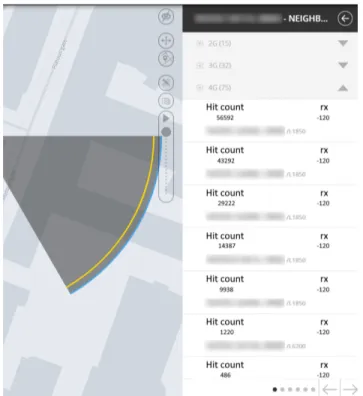
The APNI is fully integrated with Metric, allowing an operator to simply query a cell for its neighbours and sub-sequently receive a ranked Neighbour Cell List, with each hit being filtered by a user-defined signal strength (mea-sured in dBm). This information is useful for a number of applications, including the allocation of radio resources such as frequencies, codes, or identifiers while assisting with minimising interference between neighbouring cells, since coverage overlap rates can be used as a heuristic for such (i.e. two cells that have little overlap between each other probably don’t have much interference). This methodology is technology agnostic. A real world example of this use case is shown on Fig.4, with censored cell names in order to protect
FIGURE 4. The APNI in action on Metric SaaS.
the privacy of the network operator, and Fig.5demonstrates use cases relevant to the system and its user. The presented use cases can be easily run in parallel across different users thanks to the system’s cloud-based, serverless infrastructure.
FIGURE 5. Use case diagram exemplifying what a network operator can do with the APNI.
IV. EVALUATION SCENARIO
To bring the system into proper scrutiny, a real-world scenario was deliberated from a group of two-hundred and twenty-two (222) outdoor cells that share a common urban area in Oslo, Norway. Out of those cells, several of them were planned cells, which weren’t installed yet. The selection criteria for those cells included their distance to each other, their cov-erage areas and subsequent overlaps between each other, the ratio of planned cells and real cells and their technology (all of them utilise 4G).
It should be noted, however, that out of that group of cells, there were an additional sixty-one (61) cells that couldn’t be used because they were designed as indoor cells, which follow different protocols than outdoor cells. Indoor cells are specifically made to be used indoors (hence the name), and typically don’t have outdoor cells in their NCLs; for example, instead of relying on receiving and querying an NCL, an UE that enters a building with an indoor cell present and starts losing signal to an outdoor cell starts blindingly searching for another connection, which will ultimately result in a connection to the strongest available signal: the indoor cell that’s present. This simplifies the scenario, but considering that there are mobile users who mostly use their equipment outside or while commuting, it’s still a realistic case.
The purpose of this evaluation was three-fold: one, to eval-uate how the APNI performs in an urban environment com-pared to the standard ANR that the operator already uses and determine what deliberations can be made between HO events and user mobility. Two, to prove that the APNI can edit existing ones from active cells to incorporate the planned cells. Three, to evaluate if the APNI can create neighbourly
relations that are appropriate (e.g., two cells that are very far away from each other shouldn’t stack up beyond the bottom in their respective ranked NCLs). While the APNI calculated and saved every neighbourly relation between all cells, only one cell’s results will be considered, in this case an active cell in order to comply with all of the test’s purposes.
As mentioned before in Sub-sectionIII-C, the cells’ names and their base station labels were censored for the sake of the network provider’s privacy, and were labelled as cell1 to cell222, with the tested cell taking the first label. Fur-thermore, it should be noted that, in the case of active cells, the operator’s ANR rated neighbourly relations by the num-ber of successful inward/outward handovers that happened during some period of time, and for the purposes of this test the period chosen was one between mid-September 2019 and mid-October 2019. The map displayed in Fig. 6 provides a view of the aforementioned scenario, showing all of the relevant sites that host the thirty-two cells. Each site is shown as a triangle with a certain character that labels its status:
• A ‘‘P’’ means that the site is planned and isn’t installed
on location as of the chosen time frame.
• An ‘‘A’’ means that all of the site’s cells are active. • A ‘‘H’’ means that all of the site’s cells are
halted/inactive.
• A black ‘‘6=’’ warns that at least one cell differs from
the active majority on a site, for example, if one has two active cells and one halted. A red ‘‘6=’’ warns of the opposite.
The APNI was run four times with different signal strength filters, which were (in dBm): −120, −100, −80 and −60. These filters have the purpose of helping to find out what the most important neighbours are by checking which neigh-bourly relations persist over multiple signal strengths.
FIGURE 6. Excerpt from the Metric map showing the two-hundred and twenty-one cell scenario.
V. RESULTS
The test merged the ANR’s results and the APNI’s results in order to compare the rate of handover (HO) success versus the four rates of coverage according to the four parametrised signal strengths (−120 dBm, the most sensitive, −100 dBm, −100 dBm, −80 dBm, −60 dBm, the least sensitive). Since neighbourly relations have been detected between almost every single cell according to the APNI at its most sensitive filter, resulting in more than two-hundred (200) entries, only the top twenty (20) results of the following categories will be considered:
• Inbound HO Percentage (Figure7); • Outbound HO Percentage (Figure8); • −120 dBm Coverage Percentage (Figure9); • −100 dBm Coverage Percentage (Figure10); • −80 dBm Coverage Percentage (Figure11);
• −60 dBm Coverage Percentage (Figure12).
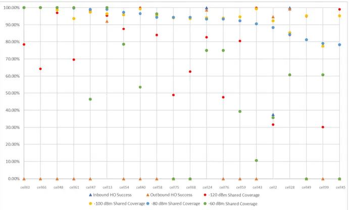
It should be noted the shared coverage shown in each Figure is exclusively between cell1’s coverage and the cells shown on the Figures; this means that, for example, while cell1shares a certain percentage of its coverage with cellX, that doesn’t necessarily mean cellX shares the same amount of its coverage with cell1, since it may occupy more space than cell1.
The results make it clear that there’s little correlation between a high shared coverage and a high inbound/outbound HO success rate, outside of a few coincidences like cell30 and cell28on Figures7 and9 (Appendix). This is because the ANR utilises data from user equipment (UE) mobility across different cells, while the APNI utilises overlapping coverage data on a two-dimensional topological grid.
On Figures 9 to 12 (Appendix) there are several cells that present a ‘‘N/A’’ rate of Inbound/Outbound HOs, which means that no Handovers have been made between cell1 and those cells. This means one of three things:
1) There’s no discernible or convenient path for mobile users to traverse in order to justify Handovers between those two cells;
2) The cell shown in the Figure is in a low-traffic zone. 3) The cell shown in the Figure is a planned cell and hasn’t
been activated yet.
Given that this scenario presents a densely populated within a densely covered urban location, the first option is likely considering that there are probably more cells in the way which the UE considers to be the better HO target; an exces-sive number of HOs to hop from one cell to another isn’t desirable, even if it implies handing over to a cell that doesn’t share as much coverage with the previous cell. Furthermore, an excessive amount of overlap isn’t desirable either, espe-cially if the rate of HOs does not justify it (such as many top examples on Figures9-12(Appendix)), as it constitutes as a waste of energy and the signal could be used better elsewhere. Therefore, the APNI is capable of providing useful data to analyse ANR trends and to find excessive overlaps with coverage data.
FIGURE 7. Dispersion between the top 20 cells from the highest to the bottom rate of inbound HO success.
FIGURE 8. Dispersion between the top 20 cells from the highest to the bottom rate of outbound HO success.
An expected observation made clear by the coverage over-lap dispersion graphs (Figures9-12) is that there’s a tendency for overlap rates to decrease faster the more sensitive the
signal filter is. For example, the top 20 cells on Figure 9
don’t go below an 80% shared coverage rate, while the ones on Figure12follow a much sharper decrease down to
FIGURE 9. Dispersion between the top 20 cells from the highest to the bottom rate of shared coverage at −120 dBm.
FIGURE 10. Dispersion between the top 20 cells from the highest to the bottom rate of shared coverage at −100 dBm.
below 50%. Furthermore, while the rates seem to be randomly spread out, there is a slight tendency that the lower signal filters share similar rates.
While definitely not the norm, the APNI could recognise potential neighbour relations between cell1 and some planned cells, such as cell54 on Figures11and12(Appendix), and
FIGURE 11. Dispersion between the top 20 cells from the highest to the bottom rate rate of shared coverage at −80 dBm.
FIGURE 12. Dispersion between the top 20 cells from the highest to the bottom rate rate of shared coverage at −60 dBm.
cell83on Figure12. Many more examples exist, though those didn’t reach the top 20 entries since they present much lower rates of shared coverages, which was likely a consequence of coverage faults or dense obstacles intercepting such signals and not a matter of distance.
The results suggest that the APNI can serve as a reliable starting point for new networks, since it can calculate neigh-bourly relations between both existing cells and planned cells through estimations of their coverage areas. It acts as a com-plement to the ANR, which works best on existing networks,
while the APNI covers the gap on planned/brand new ones; its results can also help in other manners besides neighbourly relations, like detecting overshooting (i.e. two cells that are very far away from each other shouldn’t overlap).
VI. CONCLUSION
Colloquially labelled by its technical name, Automated Pixel-based Neighbour Identification (APNI), this paper presents an implementation of a cloud-based, technologically agnostic, on-demand and automatic signal coverage based neighbour estimation system for mobile telecommunication networks, which is integrated in Metric SaaS’s ecosystem and makes full use of a network’s OSS data.
A realistic scenario was used to test the system’s per-formance in order to determine its reliability in an urban environment and draw comparisons between the network’s default ANR, such as how the user’s mobility trends compare with the topological shared coverage rates between cells, which suggests that there isn’t much correlation between the ANR’s results and the APNI’s. On another note, the system successfully managed to detect potential neighbourly rela-tions between a target active cell and planned cells, which is very useful for network planning as the manual calculations to determine such relations can be slow, costly and tedious. The APNI’s ease of customisation, especially on its parametris-able signal filter, makes it appropriate to estimate neighbourly relations and coverage ratios on any configuration that a network planner needs.
This system brings significant value to the self-configuration and self-optimisation paradigms of SONs thanks to its automated aspect and provided data which would be otherwise difficult to obtain, which contribute to the creation of new NCLs and the cleaning of existing ones, which on its own also helps in network planning and optimisation, reducing the operation and maintenance costs. It should be noted, however, that this system is not on its own an optimisation algorithm, it acts as a facilitator for such.
While the APNI is valuable on its own already, it’s not com-plete. Further optimisations to the system have to be made to support large-scale network planning. The current version is dependent on AWS, and some reworks are required to fit it in other cloud services. Further extensions can be made to add other filters besides signal strength, such as, but not limited to geographical coordinates, vendors and technology generations.
REFERENCES
[1] V. M. Nguyen and H. Claussen, ‘‘Efficient self-optimization of neighbour cell lists in macrocellular networks,’’ in Proc. 21st Annu. IEEE Int. Symp. Pers., Indoor Mobile Radio Commun., Sep. 2010, pp. 1923–1928. [2] R. Razavi, D. Lopez-Perez, and H. Claussen, ‘‘Neighbour cell list
man-agement in wireless heterogeneous networks,’’ in Proc. IEEE Wireless Commun. Netw. Conf. (WCNC), Apr. 2013, pp. 1220–1225.
[3] A. W. Maida, A. J. A. Carter, and H. Al Housami, ‘‘Creating neighbour cell lists,’’ U.S. Patent 8 559 953, Oct. 15, 2013.
[4] Y. Shin and S. Kim, ‘‘Virtualized ANR to manage resources for optimiza-tion of neighbour cell lists in 5G mobile wireless networks,’’ Mobile Inf. Syst., vol. 2017, pp. 1–9, Feb. 2017.
[5] D. Kim, B. Shin, D. Hong, and J. Lim, ‘‘Self-configuration of neighbor cell list utilizing E-UTRAN NodeB scanning in LTE systems,’’ in Proc. 7th IEEE Consum. Commun. Netw. Conf., Jan. 2010, pp. 1–5.
[6] W. Lei, W. Hai, Y. Yinghui, and Z. Fei, ‘‘Heterogeneous network in LTE-advanced system,’’ in Proc. IEEE Int. Conf. Commun. Syst., Nov. 2010, pp. 156–160.
[7] S. Sadr and R. S. Adve, ‘‘Handoff rate and coverage analysis in multi-tier heterogeneous networks,’’ IEEE Trans. Wireless Commun., vol. 14, no. 5, pp. 2626–2638, May 2015.
[8] N. A. Amirrudin, S. H. S. Ariffin, N. N. N. Abd. Malik, and N. E. Ghazali, ‘‘Analysis of handover performance in LTE femtocells network,’’ Wireless Pers. Commun., vol. 97, no. 2, pp. 1929–1946, Nov. 2017.
[9] N. Zhou, ‘‘Research on several key technologies for 5g,’’ in Proc. 3rd Int. Conf. Mechatronics Eng. Inf. Technol. (ICMEIT). Paris, France: Atlantis Press, Apr. 2019, doi:10.2991/icmeit-19.2019.67.
[10] J. M. Vidal and M. A. S. Monge, ‘‘Framework for anticipatory self-protective 5G environments,’’ in Proc. 14th Int. Conf. Availability, Rel. Secur. (ARES). New York, NY, USA: ACM, 2019, p. 105, doi: 10.1145/3339252.3341490.
[11] L. Qian, Z. Luo, Y. Du, and L. Guo, ‘‘Cloud computing: An overview,’’ in Cloud Computing, M. G. Jaatun, G. Zhao, and C. Rong, Eds. Berlin, Germany: Springer, 2009, pp. 626–631.
[12] Metric. Accessed: Sep. 3, 2019. [Online]. Available: https://www.metric.pt [13] D. Fernandes, G. Soares, D. Clemente, R. Cortesao, P. Sebastiao, F. Cercas, R. Dinis, and L. S. Ferreira, ‘‘Combining measurements and propagation models for estimation of coverage in wireless networks,’’ in Proc. IEEE 90th Veh. Technol. Conf. (VTC-Fall), Honolulu, HI, USA: IEEE, Sep. 2019, pp. 1–5.
[14] A. Godinho, D. Fernandes, D. Clemente, G. Soares, P. Sebastião, and L. Ferreira, ‘‘Cloud-based cellular network planning system : Proof-of-concept implementation for GSM in AWS,’’ in Proc. 22nd Int. Symp. Wireless Pers. Multimedia Commun., 2019, pp. 311–315.
[15] Apache Software Foundation. Apache Maven. Accessed: Sep. 17, 2019. [Online]. Available: https://maven.apache.org/
[16] Serverless. Serverless Framework. Accessed: Sep. 17, 2019. [Online]. Available: https://serverless.com
[17] Amazon. Amazon Web Services. Accessed: Sep. 17, 2019. [Online]. Avail-able: https://aws.amazon.com
[18] Google. (2019). Gson—A Java Serialization/Deserialization Library to Convert Java Objects Into JSON and Back. [Online]. Available: https://github.com/google/gson/
[19] G. Smith, S. Conway, A. R. Jones, S. Sullivan, K. Miller, T. Squires, M. Opala, and J. C. Romanda, OpenCSV—CSV Parser Library for Java. Accessed: Sep. 17, 2019. [Online]. Available: http://opencsv. sourceforge.net
[20] R. Pelletier. (2018). Java Simple Quadtree. [Online]. Available: https://github.com/ryanp102694/java-simple-quadtree/
PAULO M. PINA received the B.S. degree in computer engineering from ISCTE-IUL, Lisbon, Portugal, in 2018, where he is currently pursuing the M.S. degree in computer engineering.
As a Researcher, he is working with Multi-vision, Consultoria Informática. He has two sci-entific publications as the author in international conferences and two scientific publications as the coauthor.
ANDRÉ F. GODINHO received the B.S. degree in computer engineering from ISCTE-IUL, Lisbon, Portugal, in 2018, where he is currently pursuing the M.S. degree in computer engineering.
As a Researcher, he is working with Multi-vision, Consultoria Informática. He has two sci-entific publications as the author in international conferences and two scientific publications as the coauthor.
DANIEL F. S. FERNANDES received the B.S. and M.S. degrees in telecommunications and computer engineering from ISCTE-IUL, Lisbon, Portugal, in 2012 and 2017, respectively, where he is cur-rently pursuing the Ph.D. degree in information science and technology.
As a Researcher, he is working with Multivi-sion, Consultoria Informática. He has four sci-entific publications as the author in international conferences and seven scientific publications as the coauthor.
DIOGO J. A. CLEMENTE received the B.S. degree in electrical and computer engineering - branch of renewable systems and power systems from the Escola Superior de Tecnologia de Setúbal– ESTSetúbal/IPS, and the M.S. degree in telecom-munications and computer engineering. He is currently pursuing the Ph.D. degree in information science and technology from the University Insti-tute of Lisbon (ISCTE-IUL), Lisbon, Portugal.
As a Researcher he is working with Multivision, Consultoria Informática. He has eight scientific publications in international conferences.
PEDRO SEBASTIÃO received the Ph.D. degree in electrical and computer engineering from IST.
He is currently a Professor with ISCTE-IUL’s Information Science and Technology Department, He is also the Board Director of AUDAX-ISCTE - Entrepreneurship and Innova-tion Center, ISCTE, responsible for the LABS LISBOA Incubator and Researcher at the Institute of Telecommunications.
He has oriented several master’s dissertations and doctoral theses. He is the author or coauthor of more than 200 scientific articles and he has been responsible for several national and international Research and Development projects. He has been an expert and evaluator of more than one hundred national and international Civil and Defense Research and Development projects. It has several scientific, engineering and pedagog-ical awards. Also, he has organized or co-organized more than 55 national and international scientific conferences. He planned and developed several postgraduate courses in technologies and management, entrepreneurship and innovation and transfer of technology and innovation. He has supported several projects involving technology transfer and creation of start-ups and spinoffs of value to society and market. He developed his professional activity in the National Defense Industries, initially in the Office of Studies and later as the Board Director of the Quality Department of the Production of New Products and Technologies. He was also responsible for systems of communications technology in the Nokia-Siemens business area. His main researching interests are in monitoring, control and communications of drones, unmaned veihcles, planning tools, stochastic process (modeling and efficient simmulations), the Internet of Things, and efficient communication systems.
GABRIELA E. SOARES received the B.S. degree in computational mathematics from the Univer-sidade Federal de Minas Gerais (UFMG), Belo Horizonte, Brazil, the M.S. degree in mathemat-ical and computational modeling from the Centro Federal de Educação Tecnológica de Minas Gerais (CEFET-MG), Belo Horizonte, Brazil, and the Ph.D. degree in computer science from the Univer-sidade de São Paulo (USP), São Paulo, Brazil. She has participated as a Researcher in three Research and Development projects funded by FAPESP, CAPES, and CNPQ focused on optimization, evolutionary computing, complex networks, and data sci-ence. She is working at Multivision as a Data Scientist Researcher and has 17 scientific publications in journal articles and international conferences.
LÚCIO S. FERREIRA (Senior Member, IEEE) received the Licenciado and Ph.D. degrees in electrical and computer engineering from the IST/Technical University of Lisbon, Portugal. As a Researcher, he worked with the Deutsche Telekom Innovation Laboratories, in 1998, the Instituto de Telecomunicações, from 1999 to 2012, and the INOV-INESC, from 2012 to 2015. He has been with INESC-ID, since 2016. As an Assistant Pro-fessor, he has worked in Universidade da Beira Interior, Universidade Lusiada de Lisboa and ISTEC, in the areas of com-puter science and telecommunications. He is currently the Project Manager with Multivision, Consultoria Informatica. He has participated, as a Project Manager and a Researcher, in 17 Research and Development projects funded by the European Commission. He has participated in FP7-ICT OPTINET-5G, MCN, NEWCOM++, NEWCOM#, SAIL and FORWARD, FP6-IST WIP, NEWCOM and FLOWS projects, and FP5-IST MOMENTUM and ASILUM projects. He has collaborated with the COST actions IRACON, IC1004, 2100, 273 and 259, and networks of excellence NEWCOM#, NEW-COM, and ANWIRE. At national level, he has worked as a consultant for mobile operators and ANACOM national regulator. He has more than 50 scientific publications in books, journal articles and international con-ferences, and is the Editor and the co-author of 63 technical reports for the European Commission. He reviewed 29 journal and conference papers, and participated in eight organisational commitees and 15 technical committees of international conferences. He has supervised 12 M.Sc. and three Ph.D. students. He is a board member of the IEEE ComSoc Portugal chapter.