Abstract—Quantum computer algorithms require an ‘oracle’ as an integral part. An oracle is a reversible quantum Boolean circuit, where the inputs are kept unchanged at the outputs and the functional outputs are realized along ancillary input constants (0 or 1). Recently, a nearest neighbour template based synthesis method of quantum Boolean circuits has been proposed to overcome the adjacency requirement of the input qubits of physical quantum gates. The method used SWAP gates to bring the input qubits of quantum CNOT or C2NOT
gates adjacent. In this paper, we propose cost reduction techniques such as ancillary constant determination to reduce the number of NOT gates and variable ordering and product grouping to reduce the number of SWAP gates required in nearest neighbour template based synthesis. The proposed approach significantly reduces the quantum realization cost of the synthesized quantum Boolean circuit than that of the original nearest neighbour template based synthesis.
Index Terms— Ancillary constant determination, nearest neighbour template, product grouping, quantum Boolean circuit, fixed polarity Reed-Muller expression, reversible logic, variable ordering
I. INTRODUCTION
Quantum computer algorithms require a black box called ‘oracle’. An oracle is a reversible quantum Boolean circuit, which takes a set of inputs and produces a set of functional outputs. The inputs are kept unchanged at the outputs and the functional outputs are generated along ancillary input constants (0 or 1). Thus, if the oracle has n inputs and m functional outputs, then the oracle is realized as a (n + m)-qubit reversible quantum Boolean circuit [1], where the circuit has (n + m) inputs and outputs. Therefore, synthesis of reversible quantum Boolean circuit is very important in quantum computation.
Younnes and Miller [2] introduced representation of Boolean quantum circuits as Reed-Muller expression using (k + 1)-qubit CkNOT gates. However, physical realization of CkNOT gate for k > 2 is practically very difficult and this physical constraint requires that quantum Boolean circuit be synthesized using CkNOT gates with k≤ 2. A (k + 1)-qubit CkNOT gate has k controlling inputs and one target input. The target qubit value is inverted if and only if all the controlling qubit values are 1. Physical realizations of these quantum gates require that the controlling qubits and the target qubit be physically adjacent [3]. This constraint also requires that,
Manuscript received December 11, 2007.
Mozammel H. A. Khan is with the Department of Computer Science and Engineering, East West University, 43 Mohakhali, Dhaka 1212, Bangladesh, phone: +880-2-9882308; fax: +880-2-8812336; e-mail: mhakhan@ ewubd.edu.
in a quantum Boolean circuit, the controlling qubits and the target qubit of a quantum gate must be brought to physically adjacent position using quantum SWAP gates. For this purpose, Chakrabarti and Sur-Kolay [4] introduced a nearest neighbour template based synthesis, where the controlling qubits and the target qubit are brought to adjacent positions by using quantum SWAP gates. They also used a quantum gate library consisting of only NOT, CNOT, C2NOT, and SWAP gates to overcome the physical realization problem with k > 2. In this nearest neighbour template based synthesis, besides NOT, CNOT, and C2NOT gates, a large number of SWAP gates are needed. In the present paper, we have reduced the number of SWAP gates by using variable ordering and product grouping techniques. We have also reduced number of NOT gates by judicious determination of ancillary constant value.
The rest of the paper is organized as follows. We introduce NOT, CNOT, C2NOT, and SWAP gates in Section II. Then we discuss Reed-Muller expressions of a Boolean function in Section III. In Section IV, we discuss quantum gate network for fixed polarity Reed-Muller (FPRM) expression and also discuss the ancillary constant determination to reduce the number of NOT gates. We then discuss nearest neighbour template based synthesis of quantum gate network for FPRM expression from [4] in Section V. In Section VI, we propose variable ordering and product grouping techniques to reduce the number of SWAP gates in nearest neighbour template based synthesis of quantum gate network. We calculate quantum gate counts and quantum realization costs of several FPRM expressions and compare with that of [4] in Section VII. Finally, in Section VIII, we conclude the paper.
II.SOME QUANTUM GATES
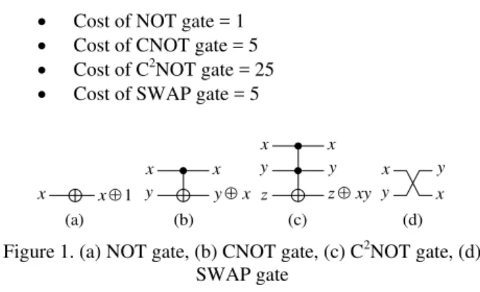
In the nearest neighbour template based synthesis of [4], a quantum gate library consisting of NOT, CNOT, C2NOT, and SWAP gates is used. In this section, we introduce these gates. These gates are shown in Figure 1. The NOT gate maps the input x →x ⊕ 1, where the ⊕ symbol represents the EXOR operation. The NOT gate inverts the input qubit value at the output. The CNOT gate maps two inputs (x, y) → (x, y
⊕x), where x is the control input and y is the target input. The CNOT gate inverts the target qubit value at the output if and only if the control qubit value is 1. The CNOT gate is also known as Feynman gate. The C2NOT gate maps three inputs (x, y, z) → (x, y, z⊕xy), where the product represents the AND operation. Here, x and y are control inputs and z is target input. C2NOT gate inverts the target qubit value at the output if and only if both the control qubit values are 1. We refer the two control lines of a C2NOT gate as top control line
Cost Reduction in Nearest Neighbour Based
Synthesis of Quantum Boolean Circuits
Mozammel H. A. Khan
and bottom control line. C2NOT gate is also known as Toffoli gate. The SWAP gate maps two inputs (x, y) → (y, x). A SWAP gate exchanges the two qubit values at the output. NMR based implementation costs of these gates are as follows [4, 9, 10]:
• Cost of NOT gate = 1
• Cost of CNOT gate = 5
• Cost of C2NOT gate = 25
• Cost of SWAP gate = 5
x x
y y⊕x
x x⊕1
x x
y
xy z⊕ y
z
x x y
y
(a) (b) (c) (d)
Figure 1. (a) NOT gate, (b) CNOT gate, (c) C2NOT gate, (d) SWAP gate
III. REED-MULLER EXPRESSION OF A BOOLEAN FUNCTION In [2] and also in the nearest neighbour template based synthesis of [4], a Boolean function is represented by its Reed-Muller expression and then the Reed-Muller expression is realized using quantum CkNOT gates. In this section, we discuss Reed-Muller expressions of a Boolean function in brief.
There are many canonical two-level AND-EXOR expressions for a given Boolean function [5]. Among them positive polarity Reed-Muller (PPRM) expression and fixed polarity Reed-Muller (FPRM) expressions are very popular. In the PPRM expression, all the variables appear in uncomplemented form throughout the AND-EXOR expression. In the FPRM expression, a variable appears either in complemented form or in uncomplemented form throughout the AND-EXOR expression. If a variable appears in uncomplemented form, we say that its polarity is 0 and if the variable appears in complemented form, we say that its polarity is 1. If a Boolean function has n variables, then the n-tupple of the variable polarities represent the polarity of the FPRM expression. As there are 2n possible choices of polarity for an n-variable Boolean function, there are 2n possible FPRM expressions for the function. In this respect, the PPRM expression is an FPRM expression with polarity 0. There are several methods of converting a Boolean function into a given polarity FPRM expression [6-8]. Here, we will not discuss the methods and the readers may see the references. The 8 possible FPRM expressions for the Boolean function
0 1 2 0 1 2 0 1 2 0 1 2 0 1
2, , ) (1,5,6,7) (
x x x x x x x x x x x x x x x f
+ +
+ =
=
∑
are given below:
0 0 1 1 2 0 1
2, , )
(x x x x x x x x
f = ⊕ ⊕ (polarity 0) (1)
1 )
, ,
(x2 x1 x0 =x2x1⊕x1x0⊕x1⊕x0⊕
f (polarity 1) (2)
0 1 2 1 2 0 1
2, , )
(x x x x x x x x
f = ⊕ ⊕ (polarity 2) (3)
1 0 1 2 1 2 0 1
2, , )
(x x x x x x x x x
f = ⊕ ⊕ ⊕ (polarity 3) (4)
0 0 1 1 1 2 0 1
2, , )
(x x x x x x x x x
f = ⊕ ⊕ ⊕ (polarity 4) (5)
1 )
, ,
(x2 x1 x0 =x2x1⊕x1x0⊕x0⊕
f (polarity 5) (6)
1 )
, ,
(x2 x1 x0 =x2x1⊕x1x0⊕x2⊕x1⊕
f (polarity 6) (7)
1 )
, ,
(x2 x1 x0 =x2x1⊕x1x0⊕x2⊕
f (polarity 7) (8)
These FPRM expressions are used in [4] to illustrate the nearest neighbour template based synthesis. We will also use these FPRM expressions for our examples.
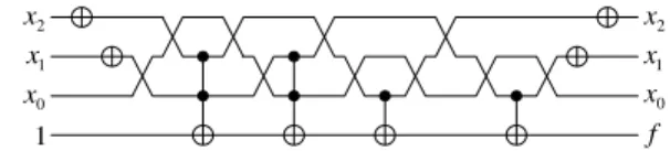
IV. QUANTUM GATE NETWORK FOR FPRM EXPRESSION In [4], an n-input single-output FPRM expression is realized using the quantum gate network model of Figure 2, where x0 to xn−1 are the n function inputs and the functional output f is realized along an ancillary constant input c = 0. In the quantum gate network of an FPRM expression, the complemented variables are first realized using NOT gates. Then, the first product term from the FPRM expression is realized using the control inputs of a CkNOT gate and the product is EXORed with ancillary constant 0 using the target input of the gate. The next product term from the FPRM expression is realized similarly and then EXORed with the previous product term (which is the target output of the previous CkNOT gate) using another CkNOT gate. In this way, EXOR sum of all the product terms are realized. Then, if the FPRM expression has a constant 1 as in (2), (6), (7), and (8), then another NOT gate is placed along the output f (since,
x
x⊕1= ). Finally, the complemented variables are restored using NOT gates. The quantum gate network for FPRM expression
1 )
, ,
(x2 x1 x0 =x2x1⊕x1x0⊕x2⊕x1⊕ f
of (7) is shown in Figure 3. Readers can see [4] for quantum gate networks for FPRM expressions of (1), (2), (3), (4), (5), (6), and (8). In [4], the ancillary constant c is assumed to be 0. The problem of this assumption is that if an FPRM expression has a constant 1 as in (2), (6), (7), and (8), then an additional NOT is required. This NOT gate can be omitted if we assume c = 1 for these cases. This rule can be generalized as
Rule 1 (Ancillary constant determination): If an FPRM
expression has a constant 1 in the expression, then assume c = 1, otherwise assume c = 0.
0
x x0
1
x x1
1
−
n
x xn−1
M M
c f
input (ancillary constant). We also assume that quantum gates are placed one after another from left to right. We describe a gate in the quantum network using the line numbers as follows: NOT(line number), CNOT(control line number, target line number), and C2NOT(top control line number, bottom control line number, target line number). For example, the first C2NOT gate from the left in Figure 3 is described as C2NOT (3, 2, 0). Using this convention, we describe the quantum gate network of Figure 3 as
f = NOT(3) NOT(2) C2NOT(3, 2, 0) C2NOT(2, 1, 0) CNOT(3, 0) CNOT(2, 0) NOT(2) NOT(3)
2
x x2
1
x x1
0
x x0
1 f
0 1 2 3
no Line
Figure 3. Quantum gate network for FPRM expression 1 )
, ,
(x2 x1 x0 =x2x1⊕x1x0⊕x2⊕x1⊕ f
V. NEAREST NEIGHBOUR TEMPLATE BASED SYNTHESIS OF QUANTUM GATE NETWORK FOR FPRM EXPRESSION
Reader can see that, in Figure 3, the control lines of C2NOT(3, 2, 0) gate are adjacent but they are not adjacent to the target line. Similarly, the control line of CNOT(3, 0) and CNOT(2, 0) gates are not adjacent to the target line. The control lines of these gates are to be brought adjacent to the target line using SWAP gates. In [4], nearest neighbour templates are introduced for this purpose as shown in Figure 4. We describe a SWAP gate as SWAP(top line number, bottom line number). Then, we can describe the templates of Figure 4 as
C2NOT(3, 2, 0) ≡ SWAP(2, 1) SWAP(3, 2) C2NOT(2, 1, 0) SWAP(3, 2) SWAP(2, 1)
C2NOT(3, 1, 0) ≡ SWAP(3, 2) C2NOT(2, 1, 0) SWAP(3, 2) CNOT(3, 0) ≡ SWAP(3, 2) SWAP(2, 1) CNOT(1, 0)
SWAP(2, 1) SWAP(3, 2)
CNOT(2, 0) ≡ SWAP(2, 1) CNOT(1, 0) SWAP(2, 1)
0 1 2 3
no Line
≡
(a)
≡
(b)
≡
(c) 0
1 2 3
≡
(d)
Figure 4. Nearest neighbour templates for (a) C2NOT(3, 2, 0), (b) C2NOT(3, 1, 0), CNOT(3, 0), and CNOT(2, 0)
The nearest neighbour templates require a large number of SWAP gates. In [4], rules for calculating the number of SWAP gates are given, but the rule statements are ambiguous and do not directly agree with the examples. However, the example calculations are correct. Here, we state rules for calculating SWAP gates very clearly.
Rule 2 (Number of SWAP gates needed for C2NOT gate):
Let, in a C2NOT gate, t be the top control line number and b be the bottom control line number. Then the number of SWAP gates required to bring the control inputs adjacent to the target input is 2(t + b−3).
Example: For C2NOT(3, 2, 0) gate, t = 3 and b = 2. Then the number of SWAP gates needed is 2(3 + 2 − 3) = 4.
Rule 3 (Number of SWAP gates needed for CNOT gate):
Let, in a CNOT gate, c be the control line number. Then the number of SWAP gates required to bring the control input adjacent to the target input is 2(c−1).
Example: For CNOT(3, 0) gate, c = 3. Then the number of SWAP gates needed is 2(3 − 1) = 4.
Now, if we replace the C2NOT(3, 2, 0), CNOT(3, 0), and CNOT(2, 0) gates of Figure 3 by their corresponding templates, we get the quantum gate network of Figure 5, which requires 10 additional SWAP gates. The quantum gate network of Figure 5 can be described as
f = NOT(3) NOT(2) SWAP(2, 1) SWAP(3, 2)
C2NOT(2, 1, 0) SWAP(3, 2) SWAP(2, 1) C2NOT(2, 1, 0) SWAP(3, 2) SWAP(2, 1) CNOT(1, 0) SWAP(2, 1) SWAP(3,2) SWAP(2, 1) CNOT(1, 0) SWAP(2, 1) NOT(2) NOT(3)
2
x x2
1
x x1
0
x x0
1 f
Figure 5. Quantum gate network for FPRM expression 1
) , ,
(x2 x1 x0 =x2x1⊕x1x0⊕x2⊕x1⊕
f with SWAP
gates.
VI. VARIABLE ORDERING AND PRODUCT GROUPING From Rules 2 and 3, we see that the number of SWAP gates is directly proportional to the distance from the target input to the control inputs. We can reduce these distances by judicious ordering of the variables and grouping of the products of the FPRM expression. We propose here techniques for such variable ordering and product grouping.
The philosophy of variable ordering is to bring the frequent variables closer to the target input so that the number of SWAP gates needed to bring the variables adjacent to the target input is reduced. The variable ordering technique is discussed below:
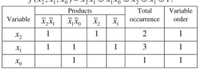
number of products in the FPRM expression) represent the products of the FPRM expression. We then determine the occurrence of the variables in the products of the FPRM expression by putting 1 in the corresponding cells of the table. For example, variable
2
x occurs in the products x2x1 and x2. Therefore, we put 1s in the intersections of the columns corresponding to the products x2x1, x2 and the row corresponding to the variable x2. In this way, we fill up the occurrence information in the table. Then, we calculate total occurrence of the variables. For example, variable x2 occurs twice and its total occurrence is 2. Then we order the variables according to their decreasing order of total occurrence. Tie is broken arbitrarily. In Table 1, the order of the variables is x1<x2<x0 and this ordering is indicated by their order number in the last column. Table 1. Variable occurrence table for the FPRM expression
1 )
, ,
(x2 x1 x0 =x2x1⊕x1x0⊕x2⊕x1⊕
f .
Products Total Variable
Variable 1 2x
x x1x0 x2 x1 occurrence order
2
x 1 1 2 1
1
x 1 1 1 3 1
0
x 1 1 1
We then rewrite the function using the decided variable order. The FPRM expression
1 )
, ,
(x2 x1 x0 =x2x1⊕x1x0⊕x2⊕x1⊕ f
of (7) is now rewritten as
1 )
, ,
(x1 x2 x0 =x1x2⊕x1x0⊕x2⊕x1⊕
f . (9)
The quantum gate network for the FPRM expression of (9) is shown in Figure 6. The quantum gate network of Figure 6 needs only 4 SWAP gates compared to 10 SWAP gates in the quantum gate network of Figure 5. The quantum gate network of Figure 6 can be represented as
f = NOT(2) NOT(1) C2NOT(2, 1, 0) SWAP(3, 2) C2NOT(2, 1, 0) SWAP(3, 2) SWAP(2, 1) CNOT(1, 0) SWAP(2, 1) CNOT(1, 0) NOT(1) NOT(2)
2
x x2
1
x x1
0
x x0
1 f
Figure 6. Quantum gate network for FPRM expression 1
) , ,
(x1 x2 x0 =x1x2⊕x1x0⊕x2⊕x1⊕
f with SWAP gates.
Now, we will discuss the product grouping technique. The motivation of product grouping is illustrated using the quantum gate network of Figure 7. Figure 7(a) represents the quantum gate network with SWAP gates for the example FPRM expression
B AC BD D C B A
F1( , , , )= ⊕ ⊕ , (10)
which needs 10 SWAP gates. If we group the products of (10) as
AC B BD D C B A
F1( , , , )=( ⊕ )⊕ ,
then the quantum gate network with SWAP gate will be as shown in Figure 7(b), which needs 8 SWAP gates. Therefore, this sort of product grouping will reduce the number of SWAP gates in the quantum gate network. In the case of such product grouping, the swapped variables are swapped back to original order after implementing all the products of the group and thus the number of SWAP gates is reduced. The rule for such product grouping is stated below.
Rule 4 (Product grouping): If a smaller product of an
FPRM expression has x number of literals and these x literals are exactly similar to the first x literals of another larger product, then these two products are grouped together. If more than two products satisfy the criteria, then they all are grouped together.
B A C
0 D
B A C
1
F D
) (a
B A C
0 D
B A C
1
F D
) (b
Figure 7. (a) Quantum gate network with SWAP gates for B
AC BD D C B A
F1( , , , )= ⊕ ⊕ and (b) quantum gate network with SWAP gates for
AC B BD D C B A
F1( , , , )=( ⊕ )⊕ .
Using rule 4, we can rewrite the FPRM expression of (9) as
1 )
( ) , ,
(x1 x2 x0 = x1x2⊕x1 ⊕x1x0⊕x2⊕
f (11)
The quantum gate network for (11) with SWAP gates is shown in Figure 8, which needs 4 SWAP gates. The quantum gate network of Figure 8 can be described as
f = NOT(2) NOT(1) C2NOT(2, 1, 0) CNOT(1, 0) SWAP(3, 2) C2NOT(2, 1, 0) SWAP(3, 2) SWAP(2, 1) CNOT(1, 0) SWAP(2, 1) NOT(1) NOT(2)
In this example, the numbers of SWAP gates of Figures 6 and 8 are same. But the motivation discussed above shows that in many situation the product grouping technique will reduce the number of SWAP gates.
2
x
1
x
0
x
1
2
x
1
x
0
x
f
Figure 8. Quantum gate network with SWAP gates for the FPRM expression
1 )
( ) , ,
(x1 x2 x0 = x1x2⊕x1 ⊕x1x0⊕x2⊕
f with product
grouping.
VII.EXPERIMENTAL RESULTS
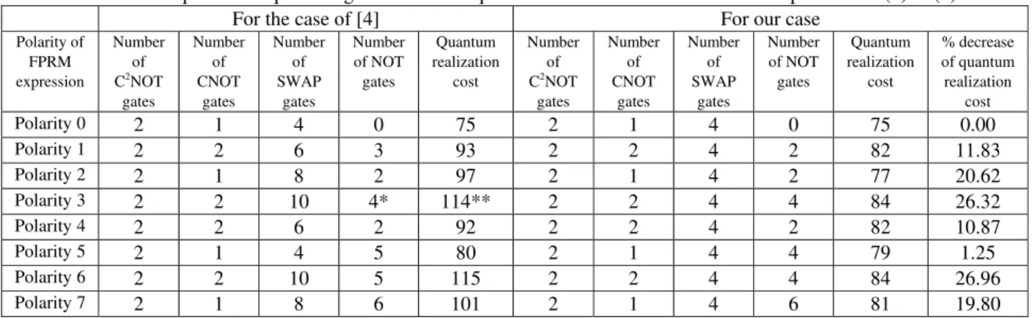
We have calculated the numbers of NOT gates, C2NOT gates, CNOT gates, SWAP gates, and quantum realization costs for the FPRM expressions of (1) to (8) and these values are compared with those from [4] in Table 2. We have also shown the percentage decrease of quantum realization costs in our approach. Table 2 shows that in one case (polarity 0) the cost of our approach is exactly the same as that of [4]. For the other seven cases the cost of our approach is 1.25% to 26.96% lesser than that of [4], which shows that the proposed approach significantly reduces the quantum realization cost. Table 2. Comparison of quantum gate counts and quantum realization costs for FPRM expression of (1) to (8)
For the case of [4] For our case
Polarity of FPRM expression
Number of C2
NOT gates
Number of CNOT
gates
Number of SWAP
gates
Number of NOT gates
Quantum realization
cost
Number of C2
NOT gates
Number of CNOT
gates
Number of SWAP
gates
Number of NOT gates
Quantum realization cost
% decrease of quantum realization
cost
Polarity 0 2 1 4 0 75 2 1 4 0 75 0.00
Polarity 1 2 2 6 3 93 2 2 4 2 82 11.83
Polarity 2 2 1 8 2 97 2 1 4 2 77 20.62
Polarity 3 2 2 10 4* 114** 2 2 4 4 84 26.32
Polarity 4 2 2 6 2 92 2 2 4 2 82 10.87
Polarity 5 2 1 4 5 80 2 1 4 4 79 1.25
Polarity 6 2 2 10 5 115 2 2 4 4 84 26.96
Polarity 7 2 1 8 6 101 2 1 4 6 81 19.80
* This count is reported as 6 in [4], which should be 4. ** This value is reported as 116 in [4], which should be 114.
VIII.CONCLUSION
In [4], a nearest neighbour template based synthesis of quantum Boolean circuit is proposed using NOT, CNOT, C2NOT, and SWAP gates. The necessity of using SWAP gates is due to the requirement of the physical quantum gates that its input qubits should be adjacent. In this paper, we have introduced variable ordering and product grouping techniques to bring the input lines of a quantum gate more close so that the number of SWAP gates required is less than that of [4]. We also proposed ancillary constant selection rule to reduce one NOT gate than the approach of [4]. Experimental results show that our approach significantly reduces the realization cost of the quantum circuit.
REFERENCES
[1] M. A. Nielsen and I. L. Chuang, Quantum Computation and Quantum Information, Cambridge University Press, 2002.
[2] A. Younes and J. Miller, “Representation of Boolean quantum circuits as Reed-Muller expressions,” arxiv:quant-ph/0304134, May 2003. [3] I. A. Grigorenko and D. V. Khveshchenko, “Single-step
implementation of universal quantum gates,” Physical Review Letters, 95, 110501, 2005.
[4] A. Chakrabatri and S. Sur-Kolay, “Nearest neighbour based synthesis of quantum Boolean circuits,” Engineering Letters, vol. 15, no. 2, 2007.
[5] T. Sasao (ed), Logic Synthesis and Optimization, Kluwer Academic Publishers, 1993, Ch. 13.
[6] M. H. A. Khan and M. S. Alam, “Mapping of on-set fixed polarity Reed-Muller coefficients from on-set canonical sum of products coefficients and the minimization of pseudo Reed-Muller expressions,”
International Journal of Electronics, vol. 86, no. 3, 1999, pp. 255-268. [7] M. H. A. Khan and M. S. Alam, “Mapping of fixed polarity
Reed-Muller coefficients from minterms and the minimization of fixed
polarity Reed-Muller expressions,” International Journal of Electronics, vol. 83, no. 2, 1997, pp. 235-247.
[8] M. H. A. Khan and M. S. Alam, “Algorithms for conversion of minterms to positive polarity Reed-Muller coefficients and vice versa,”
Information Processing Letters, vol. 62, 1997, pp. 223-230.
[9] J. Kim, J-S. Lee, and S. Lee, “Implementation of the refined Deutsch-Jozsa algorithm on a three-bit NMR quantum computer,”
Physical Review A, vol. 62, 022312, 2000.