Outubro, 2016
Hugo Miguel Mantas Costa Pinto
Licenciatura em Engenharia Eletrotécnica e de computadores
Robotic Exoskeleton Hand with Pneumatic Actuators
Dissertação para obtenção do Grau de Mestre em Engenharia Eletrotécnica e de Computadores
Orientador: Doutor José Barata de Oliveira, Professor Auxiliar, FCT-UNL
Júri:
Presidente: Prof. Maria Helena Silva Fino
Arguentes: Prof. João Almeida das Rosas
Robotic Exoskeleton Hand with Pneumatic Actuators
Copyright © Hugo Miguel Mantas Costa Pinto, Faculdade de Ciências e Tecno-logia, Universidade Nova de Lisboa.
v
“The first step is to establish that something is possible; then probability will occur.”
iii
Acknowledgements
I would first like to thank my thesis advisor Doctor Jose Barata of the Fac-ulty Science and Technology at Nova Lisbon University. The door to Prof. Bara-ta office was always open whenever I ran into a trouble spot or had a question about my research or writing. He consistently allowed this paper to be my own work, but steered me in the right the direction whenever he thought I needed it.
I would also like to thank the experts at RICS who were involved in the validation survey for this research project: Francisco Marques – PhD Student, Ricardo Mendonça – PhD Student, André Lourenço – PhD Student, Eduardo Pinto – PhD, Carlos Simões – PhD, Lino Quaresma – EngTech. Without their passionate participation and input, the development of this device could not have been successfully conducted.
iii
Resumo
Com o moderno desenvolvimento de dispositivos inteligentes moveis e com a miniaturização da tecnologia, a sociedade tem sido dotada de assistência computacional para quase todas as atividades diárias, mas os aspetos físicos são frequentemente esquecidos. Já é possível construir robôs que processam infor-mação através de redes neuronais, que exprimem e identificam expressões emocionais e que substituem o trabalho manual nas fábricas, aproximando-se cada vez mais das capacidades associadas ao ser humano. Apesar de estes sis-temas serem mantidos próximos continuam separados do ser humano, substi-tuindo-o ou executando outros serviços de suporte não sendo geralmente ado-tada a vertente de apoio simbiótico físico e direto do utilizador.
Nesta dissertação será descrita uma mão exosqueleto robótica que permite interação bidirecional homem-máquina tornando possível a assistência eletro-mecânica em diversos tipos de atividades físicas. Este sistema é desenhado de modo a imitar as funcionalidades e estrutura biomecânica da mão humana, in-cluindo mecanismos sensoriais e de controlo.
Para validação do conceito apresentado foi construído um protótipo par-cial utilizando componentes facilmente adquiridos no mercado.
iii
Abstract
With modern developments of smart portable devices and miniaturization of technologies, society has been provided with computerized assistance for almost every daily activity but the physical aspects have been frequently ne-glected. It is currently possible to make robots that process information thru neural networks, that identify and mimic facial expressions and that replace manual labour in assembly plants, getting ever closer to skills associated to human beings. In spite of these technological advances being kept close to they remain separate of humans, replacing or providing assistance with other pe-ripheral tasks, not generally adopting a direct physical symbiotic user assis-tance path.
In this dissertation a robotic exoskeleton hand will be described that al-lows for human-machine bidirectional interaction making it possible to provide physical activities with the electromechanical assistance similarly. This system is designed to mimic the human hands functionalities and biomechanical struc-ture, as well sensing and controlling systems.
A partial prototype was also built, using components easily acquired in the market, as a proof of concept.
iii
Content
1 - INTRODUCTION ... 1
MOTIVATION ... 1
OBJECTIVES ... 2
DISSERTATION STRUCTURE ... 3
2 - STATE OF THE ART ... 5
2.1- COMMON OBJECTIVE OF EXISTING EXOSKELETON DEVICES ... 5
2.1.1 - Rehabilitation or therapy ... 5
2.1.2 - Augmentation ... 6
2.1.3 - Telemanipulation ... 6
2.1.4 - Virtual Manipulation ... 7
2.2- DEGREES OF FREEDOM ... 7
2.3- JOINT MECHANISM ... 8
2.3.1 - Four-bar mechanism ... 8
2.3.2 - Five-bar mechanism ... 8
2.3.3 - Six-bar mechanism ... 9
2.3.4 - Circuitous joint ... 9
2.3.5 - Revolute joint ...10
2.3.6 - Slider-crank mechanism ...11
2.3.7 - Trapezoidal linked lever ...11
2.4- INDEPENDENT STABILITY ... 12
2.5- OPERATION CLASSIFICATION ... 12
2.5.1 - Controller...12
2.5.2 - Slave ...13
iv
2.6- DIGIT COVERAGE ... 13
2.7- SPEED ... 14
2.8- FORCE ... 15
2.9- AUTONOMY ... 15
2.10- SYSTEM CONTROL METHODS ... 16
2.11- DIFFICULTY OF USE ... 17
2.12- SENSORS ... 17
2.12.1 - Pressure ... 17
2.12.2 - Position ... 17
2.12.3 - EMG ... 18
2.12.4 - Brain-computer interface ... 18
2.13- CRITICAL ANALYSIS ... 19
3 - SUPPORTING CONCEPTS ... 21
SKELETAL STRUCTURE ... 21
Bones Tissue ... 21
Ulna/Radius ... 23
Carpals ... 24
Metacarpals ... 25
Phalanges ... 26
MUSCLE OPERATION ... 27
Sliding Filament Theory ... 28
Muscle Mechanical Attachment ... 29
NERVOUS SYSTEM ... 30
Sensory System ... 30
Sensory Information Transfer ... 32
Neural Signal Processing ... 34
MUSCULAR ANATOMY ... 36
4 - MECHANICAL ARCHITECTURE ... 41
FINGER JOINT MECHANISM ... 41
OTHER MOVING JOINTS ... 45
BRACER STRUCTURE ... 46
CRITICAL ANALYSIS ... 49
5 - ACTUATION ... 51
ARTIFICIAL MUSCLES ... 51
VALVES ... 54
HAND MECHANICAL COMPONENT ... 56
CRITICAL ANALYSIS ... 57
v
SENSORS ... 59
INSTRUMENTATION AMPLIFIER ... 61
PIC ... 63
SYSTEM ARCHITECTURE ... 65
CRITICAL ANALYSIS ... 66
7 - CONCLUSIONS AND FUTURE WORKS ... 67
GENERAL CONCLUSIONS ... 67
FUTURE WORK ... 69
8 - APPENDICES ... 79
APPENDIX A.1 ... 79
APPENDIX A.2 ... 83
APPENDIX B.1 ... 85
APPENDIX B.2 ... 87
APPENDIX C ... 89
iii
List of Figures
FIG 2.1: AN EXAMPLE OF THE FOUR-BAR MECHANISM USED TO TRANSMIT POWER TO THE PHALANGES (TAKEN FROM
[1]) ... 8
FIG 2.2: SCHEMATIC EXEMPLIFICATION OF THE MOTION FROM A FIVE-BAR MECHANISM AGAINST AN OBJECT (TAKEN FROM [2]) ... 9
FIG 2.3: SCHEME DEPICTING THE REMOTE CENTRE OF ROTATION IN A SIX-BAR MECHANISM (TAKEN FROM [8]) ... 9
FIG 2.4: SCHEMATIC OF A CIRCUITOUS JOINT MECHANISM WITH SLIDERS AND SPRING (TAKEN FROM [7]) ... 10
FIG 2.5: EXAMPLE OF A FINGER EXOSKELETON WITH A REVOLUTE JOINT ON THE INTERPHALANGEALS AND A SLIDER-CRANK MECHANISM ON THE METACARPOPHALANGEAL (TAKEN FROM [3]) ... 11
FIG 2.6: PICTURE OF THE FESTO EXOHAND THAT USES A TRAPEZOIDAL LINKED SYSTEM TO DISTRIBUTE FORCE TO THE PHALANGES (TAKEN FROM [9]) ... 12
FIG 2.7: EXAMPLE OF AN EXOSKELETON GLOVE WITH ACTUATORS CONTROLLERS AND POWER SYSTEMS INCORPORATED IN TO THE GLOVE (TAKEN FROM [11]) ... 16
FIG 2.8: EXAMPLE OF AN EMG SENSOR CONTROLLING TWO ROBOTIC FINGERS (TAKEN FROM [6]) ... 18
FIG 2.9: TWO EXAMPLES OF BRAIN-COMPUTER INTERFACES (TAKEN FROM [12], [13]) ... 19
FIG 3.1: CROSS-SECTION OF A HUMAN BONE IDENTIFYING EACH OF ITS COMPONENTS (TAKEN FROM [21]) ... 22
FIG 3.2: PARTIAL LONGITUDINAL SLICE OF A HUMAN LONG BONE WITH ITS COMPONENTS IDENTIFIED (TAKEN FROM [27]) ... 23
FIG 3.3: COUPLING OF THE ULNA AND RADIUS BONE PARALLEL AND PRONATED (TAKEN FROM [29]) ... 24
FIG 3.4: REPRESENTATION OF THE CARPAL BONES WITH THEIR IDENTIFICATION WITH THE METACARPALS LOCATED ON TOP (TAKEN FROM [31]) ... 24
FIG 3.5: ILLUSTRATION OF THE BONES OF THE HAND WITH THE METACARPALS IN RED (TAKEN FROM [34])... 25
FIG 3.6: ILLUSTRATION OF THE BONES OF THE HAND WITH THE PHALANGES IN RED (TAKEN FROM [36]) ... 26
FIG 3.7: SECTION OF THE SKELETAL MUSCLE WITH EACH SUB-LEVEL COMPONENTS (TAKEN FROM [41]) ... 27
FIG 3.8: ILUSTRATION REPRESENTING THE INTERNAL STRUCTURE OF THE MYOFIBRIL (TAKEN FROM [44])... 28
FIG 3.9: DIAGRAM OF THE SLIDING FILAMENT THEORY ACTUATION (TAKEN FROM [41]) ... 29
iv
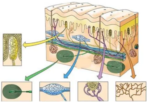
FIG 3.11: ILLUSTRATION OF THE SENSORS LOCATED ON THE HUMAN SKIN WITH THE MEISSNER'S CORPUSCLE ON THE TOP LEFT, FOLLOWED BY THE PACINIAN CORPUSCLE UNDER IT, THE RUFFINI CORPUSCLE ON ITS RIGHT, THE
MERKEL'S DISC ON ITS RIGHT AND LASTLY FREE NERVE ENDINGS (TAKEN FROM [58]) ... 31
FIG 3.12: ILLUSTRATION OF THE PATH OF THE NERVOUS SIGNALS TO THE BRAIN (TAKEN FROM [64]) ... 33
FIG 3.13: ILLUSTRATION OF THE SOMATOSENSORY AND MOTOR STRIPS AND THEIR RESPECTIVE CORTICAL HOMUNCULUS (TAKEN FROM [67]) ... 34
FIG 3.14: LOGIC DIAGRAM OF A NEURAL NETWORK ON THE LEFT AND A PICTURE OF A NATURAL NEURAL NETWORK (TAKEN FROM [70], [71]) ... 35
FIG 3.15: ILLUSTRATION OF THE THENAR AND HIPOTENAR MUSCLES OF THE HAND (TAKEN FROM [76]) ... 36
FIG 3.16: ILLUSTRATION OF THE DORSAL AND PALMAR INTEROSSEI AND THE LUMBRICAL MUSCLES (TAKEN FROM [80]) ... 37
FIG 3.17: ILLUSTRATION OF THE MUSCLES OF THE FOREARM SEPARATED BY DEPTH LAYER WITH THE ANTERIOR SECTION ON THE LEFT AND THE POSTERIOR COMPARTMENT ON THE RIGHT (TAKEN FROM [82]) ... 37
FIG 3.18: ILLUSTRATION OF THE SUPERFICIAL MUSCLES OF THE POSTERIOR COMPARTMENT OF THE FOREARM (TAKEN FROM [87]) ... 39
FIG 4.1: DIAGRAM OF THE INITIAL MECHANICAL JOINTS DIAGRAM ... 41
FIG 4.2: DIAGRAM OF THE PERFECTED MECHANICAL JOINT GEOMETRY ... 42
FIG 4.3: ILLUSTRATION OF THE BRACER DEVICE PLACED OVER THE MUSCLE DIAGRAM OF THE HUMAN FOREARM (FOREARM MUSCLE DIAGRAM TAKEN FROM [89]) ... 47
FIG 4.4: COLOUR GRADED DIAGRAM OF THE STATICAL ANALYSIS OF THE BRACER BY DEFORMATION, ON THE LEFT, AND STRESS, ON THE RIGHT ... 48
FIG 4.5: COLOUR GRADED DIAGRAM OF THE TORSION ANALYSIS OF THE BRACER BY DEFORMATION, ON THE LEFT, AND STRESS, ON THE RIGHT ... 48
FIG 5.1: ILLUSTRATION OF THE HUMAN INDEX FINGER WITH INDICATION OF THE ACTUATION LOCATION (TAKEN FROM [90]) ... 52
FIG 5.2: TWO PNEUMATIC MUSCLES INSTALLED IN THEIR SPECIFIC SUPPORTS ... 53
FIG 5.3: LENGTH OF THE ARTIFICIAL MUSCLES WITH DIFFERENT PRESSURES WHEN SUBJECTED TO A WEIGHTED LOAD. ... 54
FIG 5.4: RENDERING OF THE THREE DIMENSIONAL MODEL OF THE ROBOTIC EXOSKELETON GLOVE ... 56
FIG 6.1: RENDERING OF THE RING STRUCTURE DESIGN TO BE USED AS POSITION SENSOR ... 59
FIG 6.2: RENDERING OF THE SECONDARY RING STRUCTURE USED IN THE AS POSITION SENSOR ... 60
FIG 6.3: DIAGRAM OF THE CIRCUIT IMPLEMENTED WITH THE INSTRUMENTATION AMPLIFIER ... 62
FIG 6.4: AMPLIFICATION OF THE INPUT SIGNAL IN GREEN INTO THE OUTPUT IN RED. ... 62
FIG 6.5: DIAGRAM OF THE CIRCUIT IMPLEMENTED WITH THE MICROCONTROLLER ... 64
FIG 6.6: CONCEPTUAL MODEL REPRESENTING THE OPERATION OF THE ROBOTIC HAND. ... 66
FIG 8.1: LEFT PERSPECTIVE OF THE RENDERED ROBOTIC GLOVE ... 95
FIG 8.2: TOP PERSPECTIVE OF THE RENDERED ROBOTIC GLOVE... 95
FIG 8.3: RIGHT PERSPECTIVE OF THE RENDERED ROBOTIC GLOVE ... 96
FIG 8.4: BOTTOM PERSPECTIVE OF THE RENDERED ROBOTIC GLOVE ... 96
FIG 8.5: FRONT PERSPECTIVE OF THE RENDERED ROBOTIC GLOVE... 97
1
1 -
Introduction
Motivation
Exoskeletons are a type of skeletal architecture that surrounds the wearer instead of the traditional internal design. Exoskeleton wearable robots follow the same principle of having the pivotal structures outside its user allowing the mechanical system to be used as a suit.
This type of robotics allows an intuitive and natural interaction between human and machine where the users are not required to steer nor actively con-trol the robot but instead have only to move their body while the exoskeleton follows.
Exoskeleton structures are a common tool for therapy where they are able to restrict the wearer to the correct movements their body is supposed to exe-cute. This prevents further damage to the patients’ body while allowing the medical professional to perform the prescribed exercises, or returning some of the mobility lost due to injury or disease.
Similar exoskeleton structures can be used as input devices for easy hu-man control of separate mechanisms, as is being applied in surgical procedures allowing the remote control of specialized equipment, and in virtual environ-ment interaction where the user can interact with objects rendered inside of dig-ital devices.
2
tems together by complementing each other expanding their functionalities be-yond each of their limitations.
In this dissertation it is presented an exoskeleton hand able to mimic its biological equivalent in dexterity and flexibility reducing the limitations of pre-vious systems and reducing the volume and mechanical interference commonly associated with such devices.
Objectives
The main objective of this dissertation is to design an exoskeleton glove capable of performing the same range of movements the human hand is able to while making the joint structure self-supportive adding independent robotic capability to the device.
To achieve the set objectives several stages were identified:
Conceive a finger joint mechanism capable of performing both rota-tion and translarota-tion from the outside of the finger with reduced height and rigid movement path;
Design an ergonomic structure to support the actuators, sensors and controller coupled with the actuated hand;
Build and test artificial pneumatic muscles in order to gather data on the actuators performance;
Plan a control system to process sensory information from strain gauge in to actuator commands.
Construct a prototype of the finger joint with sensors and actuators to validate the system design.
The base requirements of the project are:
Have the same number of degrees of freedom observed in the bio-logical hand;
Self-contained system;
Invisible control approach;
3
Dissertation Structure
The dissertation is divided into six chapters which, with the exception of this introductory one, are:
Chapter 2: State of the Art Analyses of the developments made in the area of exoskeleton gloves and the different approaches to each mechanical, electrical and complexity problems;
Chapter 3: Supporting Concepts Study of the biological system the exoskeleton intends to mimic and comparison of the structural and mechanical properties used in the artificial design in relation to their organic equivalent;
Chapter 4: Mechanical Architecture Description of the design and calculations of the mechanical and physical structures developed for this project;
Chapter 5 Actuation Measurements and experimental data analysis of the built pneumatic muscles and their respective valves and supply system;
5
2 -
State of the Art
2.1 -
Common objective of existing exoskeleton devices
Exoskeleton hands have been and are being developed with different ob-jectives to be applied in distinct areas like rehabilitation, human augmentation, remote manipulation or interaction in virtual environments.
2.1.1 - Rehabilitation or therapy
Most exoskeleton hands structures are designed to help doctors perform rehabilitation exercises on patients that had a stroke or suffered from tendons or muscle injuries while, in some cases (as in [1]–[3]), allowing them to measure and record the movements and forces exerted by the patient which will help to better diagnose the condition of the injury and improve the therapeutic exercis-es and specifications.
This type of exoskeleton tend to work exclusively in slave mode where the equipment used by the patient receives commands from a computer, with a treatment plan specific for the individual patient and the device being used, or by being remotely controlled by the doctor in real time. On some cases, the user can move the robotic glove by himself, with the aid of a controller glove or us-ing EMG signals collected on different muscles that do not interfere with the hand being treated.
Devices used for this purpose tend to cover less fingers or less independ-ence between them instead focusing on slow and precise movements of each
6
articulation to reduce the discomfort for the patient and correct the disability they were designed to help repair.
2.1.2 - Augmentation
Surpassing the human limitations using robotic devices to augment strength or stamina (as in [4], [5]) is an objective that would be beneficial for both private and corporate sectors. Exoskeleton hands have been developed for
this purpose but haven’t yet been implemented, possibly due to the high cost of the device or the lack of positive feedback from this technology, caused by this technology novelty.
Increasing workers stamina would improve productivity in repetitive or straining tasks while increased strength could reduce the need of other less ver-satile mechanical equipment. Other augmentation that exoskeleton systems al-low is the addition of functionalities not available in the original biological structure (as in [6]).
2.1.3 - Telemanipulation
When humans are unable to, or put in danger if, interact directly with ob-jects there is a need to replace the human factor for a mechanical system. This is usually done with specific equipment that although work very well in regular circumstances have very limited versatility, leaving the operation susceptible to unexpected circumstances, and may not be particularly intuitive to operate, re-quiring extensive training and being prone to operating mistakes.
By applying human-like manipulation to the mechanical gripers and con-trolling those with exoskeleton master system (as in [7]) it has been made possi-ble to remotely interact with delicate or dangerous objects with similar dexteri-ty to that of the human operators while keeping them a safe distance away or outside restricted areas.
7
2.1.4 - Virtual Manipulation
One of the easiest ways to interact with a virtual environment is to grab the virtual objects as if they were in the physical world with the help of exo-skeleton sensory gloves. These devices transmit the finger movements, detected thru sensor arrays, to the computer, while most times also providing force feedback (as in [8]) which effectively gives the user the ability to touch virtual objects has if they were real.
This type of computer interaction is very useful for computer design of 3D objects and structures, allowing the designer to observe their design in different perspectives and more easily sculpt their creation, or for product designers to interact with the virtual prototype without having to have it manufactured al-lowing them to confirm that it follows the desired specifications and, if needed, improve ergonomics.
Other additional functionalities made available by this type of devices are easy hand gesture identification so that they can be interpreted by the comput-er, acting as a joystick, a keyboard or a pointer all in one for a versatile interface system (as in [6]).
2.2 -
Degrees Of Freedom
In order to reduce the complexity of the system and the number of actua-tors required, it is common to couple joints to a single actuator reducing the number of degrees of freedom and limiting the dexterity of the exoskeleton hand.
By carefully selecting which joint to couple and how to distribute the force of the actuator (as in [2], [4]) the objective for the project may still be reached with reduced costs, lighter overall device weight and lower power consump-tion.
8
2.3 -
Joint Mechanism
In an exoskeleton, the joint mechanism implemented has to be able to per-form an identical movement to that of the structure it is intended to follow or mimic.
To do that, there are almost as many methods as there are devices that ap-ply them but they can be divided by the two basic considerations taken when selecting which one to implement. If the external joint is placed in line with the centre of rotation, for example in the case of the finger, it would be placed later-ally. Alternatively it may have a remote centre of motion, requiring rotation and translation simultaneously to perform the same movement instead of exclusive-ly rotation as in the previous style.
2.3.1 - Four-bar mechanism
An inverted “V” shaped structure that, when the top pulley is pulled down, opens the joint and can be closed by pulling the two bases together (as illustrated in Fig. 2.1). By adjusting the pulley diameter it is possible to rotate the bar connecting the mechanism to the farthest base to accompany the move-ment of the users finger but it is not very reliable due to slipping of the cables over the pulleys leading to devices using this mechanism to always require an internal skeletal model, either an users hand or a prosthetic substitute.
Fig 2.1: An example of the four-bar mechanism used to transmit power to the phalan-ges (Taken from [1])
2.3.2 - Five-bar mechanism
9
identical force thru all of its length without cables passing thru all the pulleys of each finger joint.
This technique, although beneficial for reducing actuation complexity, also eliminates the possibility of adding more degrees of freedom to an individual finger due to the structure requiring the mechanical linkage to create the rotat-ing motion.
Fig 2.2: Schematic exem-plification of the motion from a five-bar mechanism against an object (Taken from [2])
2.3.3 - Six-bar mechanism
Unlike the previous two approaches to external joint movement, this six-bar mechanism is able to produce rotation and translation independently of an internal skeleton making it possible to move autonomously like a robotic hand. Another difference with previously described mechanisms is that the rigidity of the rotation gives it a fixed remote centre of rotation (as represented in Fig. 2.3) meaning that it cannot be implicitly adapted to different length fingers.
This system works in a similar fashion to a scissor mechanism where the width between the bases gets longer as the height of the structure gets shorter. The difference is that the interconnectivity between the two bases and two extra bars adds rotation to the bases mimicking the rotation and translation of the
us-ers’ fingers articulation.
Fig 2.3: Scheme depicting the remote centre of rotation in a six-bar mechanism (Taken from [8])
2.3.4 - Circuitous joint
10
With the repulsion force exerted by a compression spring pushing on the centre of the gears axis the mechanism flexes, returning to the linear position when a cable pulls on the outer section. The system is stable and rigid, allowing it to move independently from an internal structure but it is also not adjustable to different sized hands and the spring limits the grasping dynamic to a specific maximum performance, because the force and speed of the springs’ extension cannot be altered.
Fig 2.4: Schematic of a circuitous joint mechanism with sliders and spring (Taken from [7])
2.3.5 - Revolute joint
Pining both sides of a moving joint together concentrically (as shown in Fig. 2.5) to the rotation centre is the simplest method to make sure the move-ment will be executed along the expected path in a rigid and reliable way while allowing the movement to be actuated around the pivot with a plain pull or push of the dependent side.
11
Fig 2.5: Example of a finger exo-skeleton with a revolute joint on the in-terphalangeals and a Slider-crank mecha-nism on the metacarpophalangeal (Taken from [3])
2.3.6 - Slider-crank mechanism
Combining a revolute joint with a longitudinal sliding base results in a mechanism that can slide from the original position of an extended finger to the length of its flexed position with the revolute section providing the angular component of the movement (as shown in Fig. 2.5).
Being a solution for the translation problem, occurring in outer path of the human fingers flexing motion, similar to the circuitous joint but without the gears to keep the motion regular makes this a less reliable approach to the issue but the sliding mechanism allows for self-adjusting finger length that was not possible in some of the previously described joints.
2.3.7 - Trapezoidal linked lever
A trapezoidal mechanism (as shown in Fig. 2.6) is similar to the five-bar mechanism in design and use but with less mechanical parts. This system is able to apply force to the outside of the entire finger thru progressively lower levers that redirect the energy toward the closing movement of each finger sec-tion with a balanced distribusec-tion of pressure.
12
Fig 2.6: Picture of the Festo Exohand that uses a trapezoidal linked system to distribute force to the phalanges (Taken from [9])
2.4 -
Independent Stability
The structure selected for the joint mechanism can impact the available functions of the exoskeleton. If the articulation between the moving parts of the glove is able to reliably and repeatedly reproduce the human motion without an internal skeletal structure to guide the movement (as in [8]) and the length of each section can be locked or is fixed then the exoskeleton mechanism is able to act as a robotic hand. This makes it possible to use the same device for tele-manipulation without having to calculate the corresponding action for the movement detected in the master glove.
2.5 -
Operation Classification
An Exoskeleton systems operation can be divided in to two generic classi-fications, it can either be a controller or a master, which detects commands from a user and transmits them to a receptive device, or it can be a slave system that receives commands from an external device and operates according to the in-structions acquired. Most devices, to some extent, combine parts of each of these operation classes by having the controller collect data from the slave to transmit to the user as feedback or by having both the sensors and actuators in to a single device making it able to move itself according to data collected by sensors in the actual mechanism.
2.5.1 - Controller
13
Exoskeleton master gloves (as in [8]) are covered with sensors to detect a variety of data ranging from movements to pressures and forces that can be de-coded and interpreted by processing unit and transmitted to the virtual envi-ronment simulator or slave robotic device.
The movement of sensor gloves is sometimes restricted by feedback actua-tors that limits the users’ movements according to the resistance the slave de-vice encounters, this is very useful specially when manipulating objects in vir-tual environments, by adding one more sensory input to the user.
2.5.2 - Slave
When a robotic system follows instructions given by a second device the
first one is classified as a “slave” and some exoskeleton gloves (like in [3]) work in this manner, where the movement imposed by the actuators is controlled by instructions on a computer or from a secondary device, like a different exoskel-eton glove or a separate sensor like EMG or brainwave reader.
The use of this configuration is common in therapeutic applications where the medical practitioner instructs the mechanical device to move in a particular manner in accordance to the prescribed exercises appropriate for the patients’ condition.
2.5.3 - Exo Follow Hand
Combining the previous two operation classifications results in an exo-skeleton capable to follow the human hand (as in [4]), making it invisible while wearing, or to even help with the users activities, augmenting force or stamina (as in [5]).
Devices that can follow a users’ movement can also be used instead of each of the previous ones, not being limited by hardware, making them a more versatile choice.
2.6 -
Digit Coverage
14
necessary number of digits or make them modular to allow for users to adjust the configurations according to their needs.
In therapeutic and medical applications, the focus is on individual fingers and here is where there are more examples of modular (as in [3]) or coupled finger mechanism. This is an advantage for both the patient and the physician because the first has to endure less discomfort from having this equipment im-posing exercises on damaged or injured parts and for the doctor for it allows him to precisely apply treatments without interfering with adjacent digits.
For telemanipulation and virtual manipulation, the usual approach is to only include in the exoskeleton glove the index and thumb (as in [8]). This al-lows controlled mechanism or simulation to act as a claw, grasping objects with sufficient precision without cluttering the processing unit with extraneous sig-nals from the remaining fingers.
When the purpose of the exoskeleton is to improve on human limitations or more dexterity is needed a full hand is designed (as in [4]), but even in this situation some concessions are granted. Due to the importance of the index and thumb for the grasping motion these two are always included but the remain-ing fremain-ingers may be coupled or given less degrees of freedom. It is possible to find examples of coupling of the ring and little finger to a single sensor or actu-ator or even to have the little finger not included in the project. Due to the lim-ited utility of the last finger it is understandable that, to reduce overall complex-ity and weight, this digit is coupled with the adjacent one or simply not includ-ed.
2.7 -
Speed
Finding a balance between precision and speed is hard when the system has no way of knowing the amplitude of the desired movement. If we consider in addition to this the signal filtering, required to eliminate noise associated with the irregular circumstances the sensors are operating in, and the delay as-sociated with the operation of the actuators, the result is a slowed reaction speed that will reduce the precision of the movement in fast and short actions.
imper-15
ceptible to the human eye but it adds to the noise of the sensor and interferes with the movement of the human finger.
Most exoskeleton devices developed are meant to be used in average or slow hand movements avoiding problems associated with the mechanical limi-tations of fast impulses.
2.8 -
Force
Grasping force is a parameter that is often put in to the compromise sec-tion to be reduced in exchange for lighter mechanism and more precise move-ment. This relation between power and weight results from the predominant use of electric actuators that to provide more power have to be bulkier than other equally efficient but less powerful models.
Some exoskeletons use a different actuation type that relies on energy sources that are not electric (as in [10]), still requiring electric energy to control the device. This systems can outperform the human hand but are less precise and, depending on many factors, for the most part are slower than the electric actuators.
2.9 -
Autonomy
Autonomy is a problem affecting many electronic devices, mainly due to the low energy density in current batteries. This is more pronounced on equip-ment that require more powerful actions for example when an exoskeleton de-vice tries to match or surpass the human mechanical strength. Due to this, and the fact that with increased number or volume of batteries, the global weight of the device also increases, making it harder to transport, most exoskeleton gloves opt for stationary power supply, and since it is going to be grounded they move the controller, and sometimes the actuators, to an external station as well.
16
The alternative being applied to add mobility to the exoskeleton mecha-nisms is to make them less powerful and less dextrous reducing the power re-quirements and the active time of the device making it able to be easily carried and used (as shown in Fig 2.7).
Fig 2.7: Example of an exoskele-ton glove with actuators controllers and power systems incorporated in to the glove (Taken from [11])
2.10 -
System Control methods
Controlling an exoskeleton glove depends on several mechanical and con-ceptual factors but the first differentiation on which approach to take is if the glove will be working in a master or slave configuration, or both shadowing the user.
For a slave type controller the system must be able to move to the same position, or apply the same pressure, instructed by the master and, when capa-ble, respond with the sensory information of obstacles to the movement.
In a master glove, the objective of the controller is to detect the movement intended by the user and translate the adequate command to the slave system while keeping constant distance to the human finger or constant pressure on the fingertips. In case the exoskeleton hand has feedback capabilities the con-troller will have to be able to change detection methods, from position, when the slave system is free to move, to pressure sensing, to indicate how much force the motors must apply, and control its own actuators to mimic the resis-tive force felt by the slave device.
17
2.11 -
Difficulty of Use
For the most part, exoskeleton gloves are easy to use. They are either de-signed to sense the users’ movements or to impose certain exercises regardless of the users will, but some have separate controls that are not intuitive, requir-ing some trainrequir-ing and calibration.
Regardless of the control method, they all impose upon the wearer the sense that he is not simply moving his own body but that there is something else restricting his movements, in reaction speed or added weight, and some-times improving on his limitations, for example improving strength and stami-na. No exoskeleton developed outside of science fiction is completely invisible to the users’ senses but many try to make its restrictions negligible, especially compared to the advantages it brings.
2.12 -
Sensors
Almost all exoskeleton gloves requires sensors to work, even if those sen-sors are not on the device they will be connected to its controller and be used to either collect data for analyses, for medical purposes for example, or directly translated in to commands for movement actuation or remote manipulation, in either real or virtual environments.
2.12.1 - Pressure
Measuring the pressure exerted by the user on the sensor allows the tem to adjust the power provided to the actuators, whether in the original sys-tem or the slave device.
This is the only sensor type that allows for the user to directly adjust the force the grasping device or the exoskeleton will exert on the object held, if the object is removed this sensor will lose the signal indicating for the actuators to stop the movement unlike the following sensors.
2.12.2 - Position
18
Regular calibration is required for some of these sensors so continuous operation for long periods of time result in reduced precision and are danger-ous if used alone because they may cause damage to the object they are holding or even to the glove itself by exerting excessive force to try to reach the desire position.
2.12.3 - EMG
Electromyography is used by some systems as an input technique that measures the electrical activity of the users’ muscles (as shown in Fig. 2.8) and instructs the actuator to perform the task corresponding to that signal, those commands are assigned to each relevant electrical signal measurable.
Signal decomposition is difficult due to the uncertainty of the muscle posi-tion, the sensor is located on the skin surface and the muscles change their rela-tive position with unrelated movements, and the fact that electrical impulses from deeper muscles interfere with those originated by surface muscles making the positioning and reliability of this type of sensors for robotic control an issue.
Fig 2.8: Example of an EMG sensor controlling two robotic fingers (Taken from [6])
2.12.4 - Brain-computer interface
By means of electroencephalography (EEG) the electromagnetic fields generated by electric communication between neurons can be detected and roughly identified (as exemplified in Fig. 2.9). With this type of sensor the user can instruct the actuators with the desired movement just by thinking it but it is very hard to distinguish signals from each other and it requires a lot of practice and concentration to be used properly.
19
Fig 2.9: Two examples of brain-computer interfaces (Taken from [12], [13])
2.13 -
Critical analysis
Most of the systems developed so far have been purpose oriented, with functional limitations intended to improve the overall performance and reduce complexity and cost of the device.
By combining good examples from different implementations and design-ing new architectures to improve the performance of previous mechanism, it is possible to overcome the limitations of previous projects creating a more func-tional and multi purposed equipment.
To create an electromechanical system able to provide assistance, or re-motely replace, the biological human hand in an efficient and symbiotic way many different disciplines have to be involved. For the study of the biomechan-ical structure and movement vectors the development team will require some anatomical knowledge. A mechanical and physical perspective will work in close proximity to the previous knowledge base to create an adequate artificial substitute structure, this has to be able to provide support in excess to what the original structure is capable of while allowing for an identical combinations of movements. The devices artificial nervous, cognitive and actuation functions will require electrotechnical expertise, for the sensory component and pro-cessing as well as for triggering actuation, regardless of the nature of the select-ed actuators.
20
able to match the flexibility of the system it is meant to follow, this excludes some approaches taken by some exoskeleton devices that have implicit limita-tions.
These approaches to imitate the biological model are extended to the number of fingers covered by the device and on a different level to the force ex-erted and the reaction and movement speed, although these last two character-istics have technological limitations unlike the other mentioned that were de-sign problems.
The joint mechanisms described show a wide range of geometrical ap-proaches to the remote centre of rotation problem, most of which have passive adjustments for the translations component of the motion or are unadvisable for full hand applications due to discomfort or risk of injury to the user. A rigid and completely and continuously controlled method is preferable, similar to the six-bar mechanism although the mechanism profile can be lowered for better object manipulation.
Many devices have, to some level, mix operation styles, where the exo-skeleton glove is able to collect instructions from the user and applies motion to the mechanism, either directly or as a response to the obstacle detected by the virtual or remote slave device. Implementing this approach to robotic opera-tions makes it possible to simply adjust the controller software to the intended functionality expanding the devices versatility.
21
3 -
Supporting Concepts
The biomechanical structure of the human forearm and hand serve as the bases for the exoskeleton hand and many approaches to the development of the artificial system mimics the biological. Since nature already applied real live genetic algorithms in the development of the human arm, and associated organ-ic systems, it is important to know the details of the resulting structure before creating an external support mechanism for it.
Skeletal Structure
Bones Tissue
Human bones present an endoskeleton architecture and perform different functions like mechanical, by protecting organs and providing support while allowing for articulated movement, synthetic, they are essential for the produc-tion of blood cells and hormones, and metabolic, mineral and fat storage and their associated release and metabolism control.
The relevant function to study in this case is the mechanical where its dif-ferentiated layered structure provides rigid support with flexible, shock absorb-ing, extremities and lightweight porous network interior[14].
22
material of the cortical bone and is then responsible for increasing bone thick-ness and repairing bone fracture, and it also differentiate in to chondrocytes [18] that are cartilage cells. This layer also has nociceptive nerve endings that make it sensitive to manipulation, provide the body with new blood supplied by the marrow and provide an attachment for muscles and tendons.
The hard outer layer of the bone, which displays its typical white smooth appearance, is composed of cortical bone [19] and it accounts for 80% of an adult human skeleton. This apparently uniform surface consists of multiple mi-croscopic columns, called osteon [20], each of them being agglomerations of layers of osteoblasts and osteocytes formed around a central Haversian canal and remain metabolically active, as bone is constantly being reabsorbed and created, changing the location and nature of cells in the osteon. The osteon are connected to each other by Volkmann's canals at right angles to them.
Fig 3.1: Cross-section of a human bone identifying each of its components (Taken from [21])
Inside of the cortical bone lies the cancellous bone [22], separated from the outer layers by a lamina of endosteum [23]. This layer of bone consists of thin formations of osteoblasts covered in endosteum that create the porous network of the spongy bone by forming irregular interconnection of spaces. The network structure is predominant in long bone extremities or proximal to joints, where they serve as a shock absorber of the bone due to alignment of their trabeculae towards mechanical load distribution [24], and inside vertebrae where they add to the bones structural strength.
perioste-23
um layer that could continuously repair damaged fibres from the synthetic composed material.
In each of jointed bones endings there are layers of hyaline cartilage [25], which are a smooth rubber-like elastic tissue that forms a sleek padded surface, it also covers the cancellous bone found in long bone extremities providing the joint with a denser and near frictionless sliding surface. This material produces Proteoglycan 4 (PRG4) [26] that serves as a lubricant and abrasion protection reducing the erosion of the joint surfaces.
Fig 3.2: partial longitudinal slice of a human long bone with its components identified (Taken from [27])
Ulna/Radius
24
Fig 3.3: coupling of the ulna and radius bone parallel and pronated (Taken from [29])
The muscles used for finger flexing and abduction, with the exception of the thumbs thenar eminence and the little fingers hypothenar muscles, and wrist movements are located around these bones reducing the thickness and weight of the hand making it easier to manipulate objects and interact with the environment.
Carpals
There are 8 carpal bones that separate the metacarpals in the palm section of the hand from the ulna and radius in the forearm [30, pp. 126–127]. Carpals are separated in to two groups of 4, the proximal carpals juxtapose to the fore-arm bones and the distal carpals connected to the metacarpals. The two carpal bone groups mediate the wrist movement between the hand and the forearm bones, by having the distal carpals move to accommodate the metacarpal bones according to finger position while the proximal carpals compensate the chang-ing combined profile of the previous carpals to surface of the arch formed in the ulna and radius wrist joint.
25
One of the proximal carpals, the pisiform bone, is not involved in wrist movement [32, p. 5] instead providing a anchoring point for the abductor digiti minimi distancing it from the base of the little finger, thereby giving its actua-tion a better leveraging point, and improving the abducactua-tion moactua-tion of the fin-ger. This is the only finger that requires such levering of the actuation muscle for the others use forearm muscles or the relative position to each other as dis-placement reference. This bone also forms the ulnar border of the carpal tunnel from which the median nerve emerges.
The wrist bones display a complex architecture with 7 bones dedicated to wrist movement, required due to the coupling of five metacarpals in to a single joint point composed of two separate bones, each of them with their independ-ent movemindepend-ents, and the additional movemindepend-ent of the hand in relation to the forearm bones.
Metacarpals
In the intermediate part of the skeletal hand, between the carpals of the wrist and the phalanges of the fingers, are the metacarpals [33, p. 11]. These bones form an arch in their proximal end where the row of distal carpal bones are fixed.
Fig 3.5: Illustration of the bones of the hand with the meta-carpals in red (Taken from [34])
ad-26
ducting and abducting the middle finger. The little finger, due to being at one extremity of the hand, has a different muscle called the abductor digiti minimi, which was mentioned before in reference to the function of the pisiform. The last intrinsic muscle group located beside the metacarpals are the lumbrical, used to extend the interphalangeal joint and flex the metacarpophalangeal joints.
Phalanges
Each finger of the hand has three phalange bones, with the exception of the thumb that only has two [35, Pt. II. Osteology, Ch. 6b, Sec. 3]. These bones are considered long bones in terms of their design indicating that their structure is similar to that of the femur with an identical cancellous bone extremity able absorb vibrations, preventing possible damage to the bone, and able to perform repetitive movements with minimal detrition derived from the articular carti-lage covering the sliding surfaces of the bone ends. The joints that separate each fingers phalanges and the metacarpal are actuated through the use of tendons connecting to extrinsic muscles, most of which are located on the forearm.
Fig 3.6: Illustration of the bones of the hand with the phalanges in red (Taken from [36])
27
The wide and flat expansions in human distal phalange are called apical tufts [37] and it is different in their shape in comparison to other animals due to their having cone shaped distal phalange extremities. This differentiation of the fingertip of humans makes the skeletal hand particularly adapted for pad-to-pad precision grasping improving their use in detailed and delicate operation of tools and objects.
Muscle Operation
Human muscle works in the principle of microfilament contraction [38]. The activation of the excitation-contraction coupling relies on key proteins that form a triad [39, p. 124]. The sarcoplasmic reticulum (SR) [40, p. 69], a structure that stores calcium ions, is surrounded by ryanodine receptor that releases the ions stored in the SR when stimulated by ions from synapses signals originated in motor neurons or from other SR. This calcium storage proteins are located on either side of dihydropyridine receptors, a component of the surface sarcolem-ma and transverse tubule, which serve to spread electrochemical signals, in the form of calcium ions, thru the outer surface of bundles of myofibril permeating other SR causing a flood of calcium ions in the muscle.
Fig 3.7: Section of the skeletal muscle with each sub-level components (Taken from [41])
28
Fig 3.8: Ilustration representing the internal structure of the myofibril (Taken from [44])
Myofibril are composed of long proteins including actin [45], myosin [46], and titin [47]. Myosin are adenosine triphosphate-dependent (ATP) [48][39] mo-tor proteins responsible for actin-based motility that are shaped in a two tailed coiled-coil morphology with two heads. According to the sliding filament theo-ry the myosin proteins walk along the adjacent actin-based thin filaments when subjected to the proper chemical signals.
Sliding Filament Theory
While at rest the myosin is bonded to an ATP molecule and its heads are separated from the actin filament due to the presence of tropomyosins filaments between them [49], [50]. When calcium ions are introduced in to the system they bind to troponim C causing the tropomyosin filaments to slide over the ac-tin binding site unlocking them which result in both myolin heads to close and binding strongly to them creating a crossbridge.
29
what causes rigor mortis, but once that occurs the myolin heads detach from the actin filaments as the calcium ion levels in the cells are regulated and the tropomyosin return to place blocking the acting binding sites ending the cross-bridge cycling [51, Ch. Chapter 34: The Motor Unit And Muscle Action].
Fig 3.9: Diagram of the sliding filament theory actuation (Taken from [41])
Similarly to the biological muscles the pneumatic artificial alternatives have a constant supply of energy, in the latter case not of ATP but of com-pressed air, and are contracted when exposed to an energetic signal, in the
bio-logical version it’s a calcium ion that serves the same purpose as that of the
electrical signal of the artificial mechanism. The main difference in the function-al comparison of both systems is that the organic muscle has energy stored in-side of it while at rest and the artificial muscle receives its energy after the valves receive the actuation signal.
Muscle Mechanical Attachment
Muscles are both connected to and continuous with the tendons that are, in turn, connected to the periosteum layer surrounding the bones [52]. The ten-dons are made of type 1 collagen, the same as bone, skin and organs, and con-nect to the muscle at the myotendinous junction whose extracellular matrix main components include laminin, integrin, vinculin, fibronectin and talin, which enable a strong connection between the muscle actin filaments and the tendon collagen fibres [53]. There are also Golgi tendon organ present in the junction between muscle and tendon which are a sensory receptor that senses muscle tension to better control muscle actuation.
30
protective sheath containing an internal surface that reduces attrition and an external non-compressible structure to allow for the mechanical force to be transferred from the actuator to the intended destination.
Nervous System
Sensory System
In biology, environment perception is provided by sensory receptors composed of different sensory neurons that react to stimulus and react with electrochemical signals [55]. Like all neurons they collect stimulus through dendrites [56, pp. 20–36], the input ports of neurons, but in the case of sensory nerves these branched projections transduce external stimuli in to action poten-tial by increasing the permeability to sodium ions, similar in function to calcium ions used in muscle contraction but are at least 100 times faster, in the cells membrane, meaning sodium channels will open up causing the propagation of an electrochemical impulse thru the axon, the output port of the neurons, of the nerve cell in to the next synapse and so on in to the brain cortex. Mechanorecep-tor, touch mechanical sensors, are able to react to physical stimulus with the opening of the sodium ion channels in exposed dendrite membrane.
Fig 3.10: Illustration of the structure of a neuron and its syn-apse (Taken from [57])
31
Fig 3.11: Illustration of the sensors located on the human skin with the Meissner's cor-puscle on the top left, followed by the Pacinian corcor-puscle under it, the Ruffini corcor-puscle on its right, the Merkel's disc on its right and lastly free nerve endings (Taken from [58])
Pecinian corpuscles respond only to sudden disturbances making it espe-cially sensitive to vibrations [59], this makes it possible to identify textures thru the vibrations resulting from sliding the finger on a surface. Groups of corpus-cles are able to detect deep pressure changes, like for instances when interacting with objects. This sensor is formed in the shape of concentric capsules with 20 to 60 lamellae, made of fibroblasts and fibrous connective tissue, with gelati-nous material inside of them consisting of more than 92% of water. Inside the concentric capsules there is a neurite of a single afferent unmyelinated in the sensing area, making this section uninsulated due to the absence of the myelin sheath.
Meissner's corpuscles [60, pp. 7236–7246] are rapidly adaptive receptors with low threshold, ideal for detecting light touch displaying their highest sen-sitivity when stimulated with vibrations between 10 and 50 Hz. These corpus-cles are formed as capsules of connective tissue with unmyelinated nerve end-ings in spiral coils inside of it and supportive cells arranges in horizontal lamel-lae.
32
sense physical disturbances at low frequencies, around 5 to 15Hz. The proximi-ty of these touch sensors to the surface of the skin makes them sensitive to smaller tissue displacement, of less than 1μm, and with the same nerve fibre in-nervating up to 90 endings gives it a smaller receptive field than the other sen-sors, those characteristics result in a higher resolution tactile discrimination, used for detecting fine surface patterns, like when reading Braille.
Ruffini endings [61, pp. 149–156] are slowly adaptive enlarged dendritic endings with a cigar shaped capsule sensitive to skin stretch. They are able to respond to sustained pressure with very little adaptation. Being primarily used to help with object interaction, for example helping control slippage of grasped objects, they are located in greater density around finger nails, where they have a fixed reference point to sense the amplitude of skin stretching.
These sensors distribution form a network capable of detecting a wide range of mechanical stimulus with different precision, frequency and depth of pressure. The combination of sensory information help to complement each sensory receptors limitations improving the detection, identification and inter-action with the environment and distinct objects.
Sensory Information Transfer
33
Fig 3.12: Illustration of the path of the nervous signals to the brain (Taken from [64])
34
Fig 3.13: Illustration of the somatosensory and motor strips and their respective cortical homunculus (Taken from [67])
In the primary motor cortex there is an identical cortical homunculus to that of the primary somatosensory cortex with similarly placed association of body parts [68], meaning that the part of the brain that controls the hand is lo-cated next to the part of the sensory cortex that processes touch sensation from the hand. The proportions of each body part of the cortical homunculus in the motor cortex differ from the proportions of the somatosensory cortex.
Neural Signal Processing
35
Fig 3.14: Logic diagram of a neural network on the left and a picture of a natural neural network (Taken from [70], [71])
When a specific neuron collects sensory information in their dendrites it adds the sensory input until it reaches the threshold potential that causes the voltage-gated ion channels to open causing a propagation of the signal in to ax-ons that synapse them to other neurax-ons [72]. The operation procedure inside each neuron works on the bases of collecting impulses from enough axioms to cross the threshold potential causing the depolarization of the membrane po-tential releasing a new action popo-tential to further connectors.
To exemplify a neuron responsible for detecting a specific object, like a grain of sand, will collect the signals from neighbouring neurons responsible for detecting each characteristic, its hardness, the size, the texture, the weight and so on, and if all of them are activated then this neuron will trigger an action potential meaning that it was positively identified has that specific object. Stud-ies have revealed that different action potential frequencStud-ies cause neurons to propagate the signal into neurons in different directions depending on their preferred direction [73].
36
Muscular Anatomy
Starting in the hands there are some muscles used to actuate the different movements performed by the metacarpals of the fingers, except the thumb whose metacarpal extension and abduction are located on the forearm [74].
The muscles that exclusively move the metacarpal of the little finger are collectively called hypothenar muscles and consist of abductor digiti minimi, that as indicated by the name abducts the little finger, flexor digiti minimi brev-is, dedicated to flexing of the little finger, and opponens digiti minimi which rotates the little finger towards the centre of the hand making it possible to touch the thumb [75].
Fig 3.15: Illustration of the thenar and hipotenar muscles of the hand (Taken from [76])
To rotate and flex the metacarpal of the thumb the hand has a group of muscles called thenar eminence containing three muscles named abductor pol-licis brevis, responsible for abducting the thumb, flexor polpol-licis brevis, actuates the flexion of the metacarpal of the thumb, and the opponens pollicis that ro-tates the thumb towards the centre of the hand placing its distal phalange in the path of the remaining fingers [77].
37
Fig 3.16: Illustration of the dorsal and palmar interossei and the lumbrical muscles (Taken from [80])
The flexing of the metacarpophalangeal joints independently of the prox-imal interphalangeal joints can be accomplished thru the use of lumbrical mus-cles that instead of acting directly on the bones, like most skeletal musmus-cles, are connected to other tendons and ligaments making it possible to flex the meta-carpophalangeal joints while extending the proximal interphalangeal joints [81].
In the forearm there are 19 muscles responsible for movements of the hand and fingers, 6 are dedicated for wrist movements, 4 move the thumb, one exclusively for the index finger and another for the little finger, tree to move all four fingers, thumb excluded, and 4 are used to move the forearm.
Fig 3.17: Illustration of the muscles of the forearm separated by depth layer with the anterior section on the left and the posterior compartment on the right (Taken from [82])
38
this muscle can also apply force to extend the hand when the fingers do not, or cannot, extend any further. The blended aspect of this muscle and the finger flexing muscles compromises the actuation independency of the fingers limiting the singular digit extension or flexion to a reduced amplitude before it begins to affect the neighbouring fingers.
For finger flexion there are two muscle groups responsible for different joint actuation. This separation of movement actuation is necessary to make it possible to provide a larger number of degrees of freedom to the phalanges and is accomplished by limiting one muscle group, the flexor digitorum profundus located in the deep layer of forearm muscle, to the distal interphalangeal joints and another muscle group, the flexor digitorum superficialis located in the su-perficial muscle layer, to the proximal interphalangeal joints [84].
The nerve that act the section of the 4th and 5th fingers on the flexor
digi-torum profundus is the ulnar nerve while the section of the muscle that flexes the other two fingers is the median nerve, the same that acts the flexor digi-torum superficialis, this helps to separate the movement of the fingers reducing the cross actuation of the little and ring finger to the middle and index fingers [85].
The thumb has a different muscle architecture in comparison to the other fingers in that it has separate muscles responsible for flexing, the flexor pollicis longus, another for abduction, the abductor pollicis longus, and two muscles dedicated to extend the thumb exclusively in the metacarpophalangeal and in combination with the interphalangeal joints, respectively the extensor pollicis brevis and the extensor pollicis longus [86, Ch. Chapter 9: The Wrist and Hand Complex].
By analysing the actuator distribution of the human hand it is noticeable that there are coupling of joints to the individual muscles that, even so, are able to move independently with the help of combination of antagonistic actuations from other muscles. This reduces the number of required muscles while keep-ing the freedom of movement by increaskeep-ing the systems complexity.
39
arm is in, the extensor carpi radialis longus and the extensor carpi radialis brev-is, responsible for extension and abduction of the hand at the wrist, the extensor carpi ulnaris, extends and adducts the wrist, and the anconeus muscle, that as-sists in the extension of the forearm also stabilizes the elbow and abducts the ulna during pronation.
Fig 3.18: Illustration of the superficial muscles of the posterior compartment of the forearm (Taken from [87])
Contraction of the previously mentioned posterior compartment muscles changes the topography of the forearm as well has change their relative posi-tion to the wrist and elbow during wrist pronaposi-tion and supinaposi-tion.
41
4 -
Mechanical Architecture
The idea for the development of an exoskeleton hand began with a thought exercise on how to perform the rotation and translation required for an exoskeleton finger joint with over actuation, this makes the design of the me-chanical structure of the device the logical place to approach the subject.
Finger Joint Mechanism
The mechanism design for the finger joint is based on the scissor mecha-nism which, when all parts have identical dimensions, extends in one direction as a response to the contraction in a perpendicular direction.
To change the movement path of the mechanism the dimensions of the in-tersecting sections was altered resulting in a curved motion. By analysing the change in movement path associated with different dimensions a pattern was extrapolated making it possible to tune the design thru algebraic equations in to an initial working geometry.
Fig 4.1: Diagram of the initial mechanical joints diagram
42
The initial design displayed a pronounced mechanism in the superior sec-tion of the geometry and required extensive attaching surface on both sides of the articulation. To improve this design weakness and make the protuberance less pronounced, increasing the appeal of the product for an eventual applica-tion onto a commercial product, alteraapplica-tions were made to the geometry intend-ed on rintend-educing the height of the mechanism which resultintend-ed in a curvintend-ed superi-or leaver, composed of sections C and B.
Fig 4.2: Diagram of the per-fected mechanical joint geometry
The joint mechanism diagram in the above figure has indicated the rele-vant vectors of the improved geometry able to perform the rotation and transla-tion required for an exoskeleton over actuated finger joint. Each of the letters represents one measurement with their own meaning:
“R” indicates the radius of the semicircle described by the path of the join movement in relation to the remote centre of rotation;
“A” is the distance between the edge of the finger section to the fur-thest rotational connection;
“B” and “C” are de two sections of a single rigid link that connects both finger pieces over the joining edges;
“D” the lever mechanism that imposes the desired translation and
synchronises the rotation of the joint;
“E” is the distance between the lever connections to the base and
43
The equations relating each of the dimensions and the connecting angles are as follow:
When the joint is in the flexed position the “B” link will be vertical in rela-tion to the starela-tionary finger secrela-tion and in this posirela-tion the connection ζ is
col-linear with that section making the dimension of B the sum of “A” and “R”, as expressed by equation (4.1).
(4.1) The angle α is set to be zero when the joint is closed, required
for the “B” link to be position vertically in that circumstance, and by calculating the distance to a virtual intersection of a straight line from extending “A” to the
intersection of the tangent of half the angle γ, which represent the plane of symmetry of the system, it is possible to acquire the angle α from the inverse cosine of that length, depicted in equation (4.2).
(4.2)
To attain “D” it is required to define the length of E, by applying the Py-thagorean theorem and considering D the hypotenuse of this equation, the height of the connecting point of C with D, specified by equation (4.3), as one of the remaining sides and the difference between the horizontal position of this connection and E, depicted in equation (4.4), as the last side left we get equation (4.5).
(4.3) (4.4) (4.5)
44
By using swarm partible algorithm to calculate these dimensions it is pos-sible to evaluate the error of the remote centre of rotation of the external finger joint for 600 combinations of the four variables of the equations described above in each iteration. The initial values of each variable is randomly selected within a set upper and lower boundaries. These boundaries relate to the size of each finger section of the users hand. Between iterations, each particle will adjust the values of its variables towards a combination of the best result observed by it-self and the best result observed by the swarm. After a maximum of 600 itera-tions, fewer if the particle movement inside the four dimensional space has stagnated, the values for the variables that has been determined by the swarm to be closest to ideal are presented to the user.
![Fig 2.1: An example of the four-bar mechanism used to transmit power to the phalan- phalan-ges (Taken from [1])](https://thumb-eu.123doks.com/thumbv2/123dok_br/16584214.738688/28.892.151.679.701.822/fig-example-mechanism-transmit-power-phalan-phalan-taken.webp)
![Fig 2.2: Schematic exem- exem-plification of the motion from a five-bar mechanism against an object (Taken from [2])](https://thumb-eu.123doks.com/thumbv2/123dok_br/16584214.738688/29.892.193.776.283.451/fig-schematic-exem-plification-motion-mechanism-object-taken.webp)
![Fig 2.4: Schematic of a circuitous joint mechanism with sliders and spring (Taken from [7])](https://thumb-eu.123doks.com/thumbv2/123dok_br/16584214.738688/30.892.114.745.304.558/fig-schematic-circuitous-joint-mechanism-sliders-spring-taken.webp)
![Fig 2.6: Picture of the Festo Exohand that uses a trapezoidal linked system to distribute force to the phalanges (Taken from [9])](https://thumb-eu.123doks.com/thumbv2/123dok_br/16584214.738688/32.892.105.399.83.339/picture-festo-exohand-trapezoidal-linked-distribute-phalanges-taken.webp)
![Fig 3.1: Cross-section of a human bone identifying each of its components (Taken from [21])](https://thumb-eu.123doks.com/thumbv2/123dok_br/16584214.738688/42.892.120.608.482.694/fig-cross-section-human-bone-identifying-components-taken.webp)
![Fig 3.2: partial longitudinal slice of a human long bone with its components identified (Taken from [27])](https://thumb-eu.123doks.com/thumbv2/123dok_br/16584214.738688/43.892.164.670.326.655/fig-partial-longitudinal-slice-human-components-identified-taken.webp)
![Fig 3.7: Section of the skeletal muscle with each sub-level components (Taken from [41])](https://thumb-eu.123doks.com/thumbv2/123dok_br/16584214.738688/47.892.145.781.620.833/fig-section-skeletal-muscle-sub-level-components-taken.webp)
![Fig 3.8: Ilustration representing the internal structure of the myofibril (Taken from [44])](https://thumb-eu.123doks.com/thumbv2/123dok_br/16584214.738688/48.892.198.732.83.452/fig-ilustration-representing-internal-structure-myofibril-taken.webp)
![Fig 3.9: Diagram of the sliding filament theory actuation (Taken from [41])](https://thumb-eu.123doks.com/thumbv2/123dok_br/16584214.738688/49.892.148.775.79.457/fig-diagram-sliding-filament-theory-actuation-taken.webp)