DOI: https://doi.org/10.1590/2446-4740.07417 Volume 34, Number 3, p. 198-210, 2018
Introduction
Robotic rehabilitation devices such as exoskeletons and active orthosis have greatly advanced, as they can improve the mobility and, therefore, the quality of life of people with motion impairments (Tucker et al., 2015; Chen et al.,
2016). These devices can be used for elderly or neurological patients (with paraplegia and spinal cord injury) to assist their mobility (Chen et al., 2015; Miller et al., 2016) and to recover their functional movements (Chen et al., 2013; Kim et al., 2015). Preliminary findings report promising results in the field of rehabilitation, such as the fact of sub-acute stroke patients experimenting added benefit from exoskeletal gait training (Louie and Eng, 2016), and powered exoskeletons providing individuals with thoracic-level motor-complete spinal cord injury (SCI) the ability to walk (Miller et al., 2016). All of this added to the fact that rehabilitation with both exoskeleton and conventional therapy is safe and reduces the metabolic cost of the patient (Viteckova et al., 2013).
The challenge in this field is to find appropriate control strategies for these devices, which can be adapted to the functional capabilities of the users, for a seamless cognitive and physical interaction (Viteckova et al., 2013;
Control of a robotic knee exoskeleton for assistance and rehabilitation
based on motion intention from sEMG
Ana Cecilia Villa-Parra
1,2*, Denis Delisle-Rodriguez
1,3, Thomaz Botelho
1,4, John Jairo Villarejo Mayor
5,
Alberto López Delis
3, Ricardo Carelli
6, Anselmo Frizera Neto
1, Teodiano Freire Bastos
11 Postgraduate Program in Electrical Engineering, Federal University of Espirito Santo, Vitoria, ES, Brazil.
2 Career of Electronic Engineering, Biomedical Engineering Research Group GIIB, Salesian Polytechnic University, Cuenca, Azuay, Ecuador.
3 Center of Medical Biophysics, University of Oriente, Santiago de Cuba, Cuba.
4 Department of Electrotechnology, Federal Institute of Education, Science and Technology of Espírito Santo, São Mateus, ES, Brazil.
5 Postgraduate Program in Physical Education, Federal University of Parana, Curitiba, PR, Brazil. 6 Institute of Automatics, National University of San Juan, San Juan, Argentina.
Abstract Introduction: This work presents the development of a novel robotic knee exoskeleton controlled by motion intention based on sEMG, which uses admittance control to assist people with reduced mobility and improve their locomotion. Clinical research remark that these devices working in constant interaction with the neuromuscular and skeletal human system improves functional compensation and rehabilitation. Hence, the users become an active part of the training/rehabilitation, facilitating their involvement and improving their neural plasticity. For recognition of the lower-limb motion intention and discrimination of knee movements, sEMG from both lower-limb and trunk are used, which implies a new approach to control robotic assistive devices. Methods: A control system that includes a stage for human-motion intention recognition (HMIR), based on techniques to classify motion classes related to knee joint were developed. For translation of the user’s intention to a desired state for the robotic knee exoskeleton, the system also includes a finite state machine and admittance, velocity and trajectory controllers with a function that allows stopping the movement according to the users intention. Results: The proposed HMIR showed an accuracy between 76% to 83% for lower-limb muscles, and 71% to 77% for trunk muscles to classify motor classes of lower-limb movements. Experimental results of the controller showed that the admittance controller proposed here offers knee support in 50% of the gait cycle and assists correctly the motion classes. Conclusion: The robotic knee exoskeleton introduced here is an alternative method to empower knee movements using sEMG signals from lower-limb and trunk muscles.
Keywords Robotic knee exoskeleton, Electromyography, Trunk muscles, User intention recognition, Admittance control.
This is an Open Access article distributed under the terms of the Creative Commons Attribution License, which permits unrestricted use, distribution, and reproduction in any medium, provided the original work is properly cited.
How to cite this article: Villa-Parra AC, Delisle-Rodriguez D, Botelho T, Mayor JJV, Delis AL, Carelli R, Frizera Neto A, Bastos TF. Control of a robotic knee exoskeleton for assistance and rehabilitation based on motion intention from sEMG. Res Biomed Eng. 2018; 34(3): 198-210. DOI: 10.1590/2446-4740.07417.
*Corresponding author: Postgraduate Program in Electrical Engineering, Federal University of Espirito Santo, Av. Fernando Ferrari, 514, CEP 29075-910, Vitoria, ES, Brazil. E-mail: [email protected]
Tucker et al., 2015). Thus, users and exoskeleton must work together during rehabilitation, in an intuitive and synergistic way, in order to allow more natural movements, and facilitate their involvement for an improvement at their neural plasticity (Tucker et al., 2015). For this purpose, different control approaches based on motion intention have been reported to improve the performance of the exoskeleton to execute actions that are both appropriate for the rehabilation task and corresponds to the user’s expectations (Suzuki et al., 2007; Cao et al., 2014). Hence, the user is able to execute an appropriate locomotion with the generation of voluntary commands in a human-centered system to assist the movement with minimal cognitive disruption (Tucker et al., 2015).
Recently, some impedance/admittance controllers have been proposed to regulate the interaction between the exoskeleton and the user, incorporating human motion intention (Cao et al., 2014). Impedance is intrinsicly related to the mode and amount of muscle activation involved in the performance of as given task. Therefore, control of the mechanical impedance of the limb joints is an important feature of the neuromuscular system (Mizrahi, 2015). Due to the fact that humans change their joint impedances during gait by regulating the postures and muscle-contraction levels to maintain the stability, impedance/admittance controllers are of great interest to develop control strategies for gait assistive devices. Theses controllers offer the possibility of regulating the mechanical impedance at joints according to the user’s disability level and their voluntary participation, in order to provide an effective human support through assisting their limited motor capability (Hussain et al., 2013; Cao et al., 2014).
Myoelectric activity can be sensed as an input to controllers based on motion intention as well as interaction forces exist between the device, user, and environment can be used. In fact, some studies reported works that use force sensors and sEMG signals to recognize the human-motion intention (Kiguchi et al., 2004; Suzuki et al., 2007; Tucker et al., 2015).
sEMG signals contain enough information to detect the intention of movement even in case no movement is performed (Fleischer et al., 2006). On the other hand, pattern recognition–based techniques that employ classification theory to extract the user’s intent from multiple sEMG signals have shown potential to improve the accuracy during motion intention recognition. As advantages of this approach, some studies report that a smaller learning effort might be expected from users using devices with control systems based on sEMG (Jiménez-Fabián and Verlinden, 2012). Additionally, it is reported in the
literature that using sEMG, the user can perform a desired movement, or try to do so, without creating an additional mental load (Fleischer et al., 2006).
In studies focused on lower-limb motion recognition, sEMG signals from lower-limb muscles are recorded as primary actor in locomotion (Chen et al., 2013; Lee et al., 2015). However, few works consider alternatives in cases where the subject cannot generate
sufficient muscle signals from their lower-limbs, due
to weakness or atrophy. For these subjects, it is not possible to discern and interpret their physiological state and desires (Suzuki et al., 2007). There are studies in physiotherapy reporting that, lower-limb muscles in addition to the erector spinae (ES) muscle of the trunk, on different spinal levels, play an important role in the organization of this locomotion task (Sèze and Cazalets, 2008; Swinnen et al., 2012). In (Wentink et al., 2013), the feasibility of real-time intention detection of gait initiation based on both lower-limb and ES (lumbar region) muscles was analyzed, showing that the ES muscle can provide valuable information on postural changes being used for detection of heel strike. As an advantage, the muscle recruitment of trunk precedes the muscle recruitment of the lower-limb, as the trunk begins to move earlier (Karthikbabu et al., 2012). In neurological cases, such as incomplete spinal cord injury and post-stroke patients the trunk musculature may have been preserved (Karthikbabu et al., 2012; Del Alma Espinosa, 2013), which opens the possibility of exploring this alternative for obtain motion intention information from sEMG signals of the trunk instead of the lower limbs. For this, it is important to understand how the locomotion is controlled in humans and how the user’s state and intent can be sensed (Sylos-Labini et al., 2014).
stage, which include a function that allows stopping the movement according to the user’s wish, during tasks of flexion-extension, and a stance-phase controller with admittance modulation to be used during the gait. In this approach, sit down, stand up, knee flexion-extension, walking, rest in sit down and stand up conditions are considered as motion activities. A pilot test with voluteers used the developed controller during the execution of the sequence of these motion activities.
Methods
Control system
Figure 1 shows the block diagram of the proposed system, which includes our knee exoskeleton termed ALLOR (Advanced Lower Limb Orthosis for Rehabilitation), developed at Federal University of Espirito Santo (UFES/Brazil).
The system includes a hierarchical control structure composed of a human motion intention recognition system (HMIR) at high-level. Then, for translation of the user’s motion intention for a wished state for ALLOR, the controller includes at the mid-level a finite state machine (FSM), which sets the control strategy corresponding to the recognized motion class. Finally, an admittance, velocity and a proportional integral (PI) controller are responsible for realizing the wished movement at low-level. The low-level controller sends the commands to the actuators, which move the structure of the robotic exoskeleton.
The following sections describe details of the components of the proposed system.
Advance Lower Limb Orthosis for Rehabilitation (ALLOR)
The active knee exoskeleton, termed ALLOR is composed of an active knee joint and a passive hip joint, which moves itself in the sagittal plane during the gait. It was built for knee rehabilitation in both seated position and walking, and provides both mechanical power to the knee joint and feedback information related to the knee angle, interaction torque, and gait phases. ALLOR has a mechanical structure of aluminum (type 7075), which is attached to the user’s joints. It was built using active orthoses design-criteria for lower-limb devices for assistance and rehabilitation reported by (Villa-Parra et al., 2015). It is mounted on the left leg of the user, and is adaptable to different anthropometric setups, which include heights of 1.5 to 1.85 m and weights from 50 to 95 kg. To ensure a correct alignment during operation, a backpack and rigid braces are used. The backpack consists of shoulder straps and a belt that wraps around the wearer’s waist. The belt is adjusted at the hip joint to sustain the orthosis structure. In addition, the backpack was adapted to place the sEMG electrodes at trunk, which includes a free space to access them at the lumbar area of the user, and a cover for the area. The rigid braces are covered with a soft material, and are adjustable through velcro straps to different diameters and lengths of the user’s thigh and shank. The total weight of ALLOR is 3.4 Kg, including 0.8 kg of the backpack.
The hip joint has a manual flexion-extension angle regulator (0 to 80°). Although this joint is not active, its regulation, according to the user requirements, allows establishing a safe range of motion.
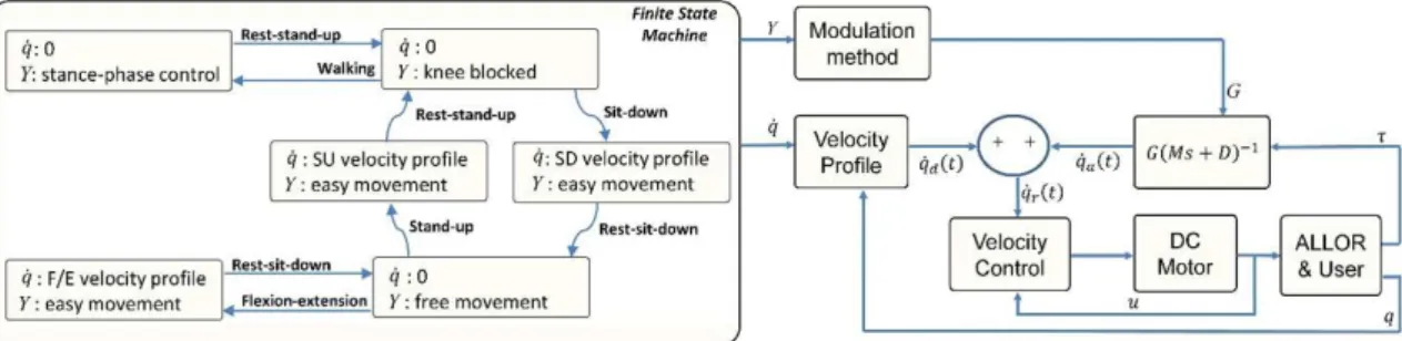
Figure 1. Block diagram of the proposed system. At the high-level, the system includes the estimation of the motion class through the human motion intention recognition (HMIR) system, which processes sEMG signals acquired from the user. The output of the HMIR is used to select
a state with a finite state machine (FSM) defining both wished admittance and parameters for the velocity and trajectory low-level controllers to
The components of the active knee joint are a brushless flat motor (model 408057), a Harmonic Drive gearbox (model CSD-20-160-2A-GR) and an analog PWM servo-drive (model AZBH12A8). Additionally, ALLOR is equipped with a strain gauge arrangement (Wheatstone bridge configuration), which measures the torque produced by its interaction with the user. A precision potentiometer (model 157S103MX from Vishay Spectrol) is used as an angular position sensor to measure knee angles, and an instrumented insole with four FlexiForce A401 resistive force sensors is used for both measure plantar pressure and to recognize gait phases. ALLOR also uses Hall Effect sensors inside the motor to compute angular speeds of the actuator.
The computer used to implement the control software is a PC/104, which is a standard for embebbed computers. The modules are a motherboard, power source, ethernet communication and an analog to digital acquisition card, model Diamond-MM-32DX-AT (32 input of 16 bits, 4 output of 12 bits, with maximum sampling frequency of 250 kHz). All sensors, acquisition and velocity driver are connected through the A/D card. The whole system requires 24 V/12A DC power supply, and uses CAN bus running at 1 Mbps.
The control software was developed in Simulink/ Matlab, and uses real-time target library. Safety conditions are incorporated at the ALLOR control system along with mechanical stops in the physical structure, which ensure that the actuator operates within the normal range of motion of the knee, allowing safe use.
Human-motion Intention Recognition (HMIR)
The controller comprises the HMIR system based on sEMG signals, which are acquired on the trunk or lower-limb muscles, in order to recognize the following motion classes: 1) Stand-Up (SU); 2) Sit-Down (SD); 3) Knee Flexion-Extension (F/E); 4) Walking (W); 5) Rest in Stand-Up Position (RSU); 6) Rest in Sit-Down position (RSD). This stage aims to conveying control commands to the active knee exoskeleton. This way, two stages of classifications (C1 and C2) are used to recognize, respectively, the following two class groups: 1) Siting movements, termed G1, which includes the sequence SU-F/E-RSD; 2) Standing movements, termed G2, which includes the sequence RSU-W-SD. The classes SD and SU are taken into account to select the correspondent classification stage C1 and C2, respectively, hence these are the states of transition between both classifiers. Then, once detected the SD class, the three classes corresponding to G1 are recognized, while another group G2 is recognized after detecting the SU class. The raw sEMG are pre-processed to remove the DC component. Feature vectors are extracted from sEMG in the classificacion stage, using window length
of 80 ms, overlapped each 40 ms. In this stage, are used the following features: slope sign changes (SSC) and zero crossing (ZC) at time domain; and total power
(TTP) and autoregressive (AR) coefficients of order
4 at frequency domain. These are common features used in literature for applications aimed controlling robotic assistive devices with sEMG signals (Lee et al., 2015; Mayor et al., 2017). Each feature is normalized individually based on average and standard deviation values. In this study, multi-class support vector machine (SVM) with Gaussian kernel (also known as radial
basis function RBF, with C=1 and σ=10) (Oskoei and
Hu, 2007) was used. During the supervised learning, the classifier is trained through the first six trials from a sequential experiment, and four trials from a random experiment. For validation, the remaining four and two trials are considered from the sequential and random experiments, respectively.
Finite state machinne and low level controllers A finite state machine (FSM) is used to establish a model for the transitions of the sequences: siting movements G1 (SU-F/E-RSD) and standing movements G2 (RSU-W-SD), according to the user’s motion intention. The objective is to generate control commands corresponding to the recognized motion class from the HMIR system. Once the command of the HMIR is received, the FSM uploads the corresponding parameters of velocity (q) and admittance (Y) to activate the low-level controller. Figure 2 shows the FSM configuration and low level controllers that includes admittance, velocity and trajectory controllers. This approach was proposed based on the user’s movements considering activities of daily living and the advantages of each controller implemented and tested in ALLOR.
The admittance controller is employed to assist the knee joint during W state and to provide knee support during RSU position. On the other hand, the velocity controller is employed to execute F/E movements, and the trajectory controller is employed to execute movements in both SD and SU states. Each action of control includes an output to define the end of the action, in order to resume the HMIR system.
The admittance control is performed through a transfer function of first order that relates the input force with other variables, such as torque, inertia, and damping, expressed through Equation (1).
( ) ( )1
a
q• s = τG Ms+D− (1)
where qa
•
For the W state, Y activates a modulation method to generate a stance control (SC) with admittance modulation over the gait cycle. SC is a strategy to assist the knee joint reported as a good alternative to facilitate ambulation with a more natural gait (To et al., 2011; Zacharias and Kannenberg, 2012). Higher admittance values are desired when the user performs gait sub-phases that has ground contact, while lower values are used during movements of great acceleration, such as the case of the leg movement during the swing phase. For this purpose, a modulation method is employed to generate a suitable gain (G) to adjust M and D through information related to gait phases obtained from the footswitch insole (Villa-Parra et al., 2017). The gait phases considered are: initial contact, defined by the heel contact; mid-stance, defined by a flat foot contact; terminal stance, defined by the heel off; and swing, defined by the foot-off. During the gait cycle, different G values for each gait sub-phase are applied. In order to obtain a smoother response, an increment of G during a time ∆t is considered. The value of ∆t for each sub-phase is calculated from the gait velocity and stride length, which can be estimated through the value of the user’s height in meters multiplying by the constant 0.826 (Arnos, 2007). Experimental tests to analyze the period of each sub-phase were conducted, in order to obtain the Equation (2).
( )
0.0413 /
s
t i H v f
∆ = (2)
where ∆t represents the time in seconds (this function increases its value until the admittance required at the knee joint), i is the sub-phase (1 for IC, 2 for MS, 3 for TS, and 4 for SW), H is the height in meters of the subject, v the velocity (m/s) during gait, and fs is the sampling frequency in samples per second. When the sub-phase is recognized, G varies during the corresponding Δt. For our approach, the gains have the following proportions: 4 for IC, 7 for MS, 2 for TS and 1 for SW. The default values of inertia and damping were experimentally obtained in tests with ALLOR, and correspond to a ratio M/D = 0.2. In this state W, the variable q uploads a velocity of
reference equal to zero in order to allow a force control without guided movement.
For the state RSU, Y activates an admittance to lock the joint, preventing movement. This way, ALLOR helps to support the user’s weight and, with the use of walkers or canes, prevent user’s falls. q allows a control without
guiding the movement, with a velocity equal to zero. For the RSD, Y activates an admittance at the knee
that allows an easy knee movement, and q allows a
control without guiding the movement.
For the F/E state, q activates a path velocity to let
the joint execute movements between qmin and qmax,
which expreses the limits of the movement in degrees, provided by the algorithm shown in Figure 3.
Here, the inputs qmin and qmax represent the limits of the F/E movement, and downtime and uptime define the periods of time (t) in seconds in which the leg stays at extension and flexion, respectively.Additionally, at the motion class F/E, a strategy to detect the user’s intention of stopping was included, employing the following hyperbolic function defined by Equation (3).
( )
1 tanh
A= ± kτ (3)
where k is a constant that represents the level of effort that the user requires to stop or accelerate the movement. The hyperbolic tangent function with offset = 1 produces a gain GFE in absence of motion intention, and does not change the programmed velocity profile. This function allows increasing GFE in order to accelerate or decelerate the movement. On the other hand, if the user has a intention of stopping, GFE approaches to zero, stopping the movement. The value of k is determined empirically and individually as the torque generated by each subject is different. Once determined, it is kept constant throughout the tests for a specific subject.
For the states SD and SU, q activates the PI trajectory
controller in order to let the joint execute the corresponding movement. As reference data, a recorded trajectory using ALLOR is considered.
Figure 2. Finite state machine with two outputs velocity (q) and admittance (Y), which activate the modulation of admittance parameters and the velocity
Although in this approach the user’s motor intention commands the execution of the movements, to start the new desired movement it is necessary to have completed the previous movement. This is done in order to obtain the correct discrimination of the movements by users and to warrant the user safety. For standing movements, previous to begin the W state, the SU state needs to be completed with the user properly supported by both ALLOR and walker. It is considered that the W state is completed when two steps are executed by the user (the number of steps can be adapted depending of the user condition). Then, the user can begin another movement based on his/her intention information. For siting movements previous to the F/E state it is necessary to complete the SD state.
Experimental protocol
The experimental protocol was divided in two parts: 1) sEMG signal acquisition; 2) pilot test of the controller. The experimental protocol number: 47024214.5.0000.5060 was approved by the Ethics Committee of the UFES. All subjects have provided written informed consent before participation. The sEMG signal acquisition is done directly from the trunk and lower limb muscles during the execution of all motion classes, initially without ALLOR, in order to compare the pattern recognition algorithm performance with all muscular groups. The pilot test was proposed to validate the controller with the exoskeleton during the execution of a sequence of motion classes.
sEMG acquisition
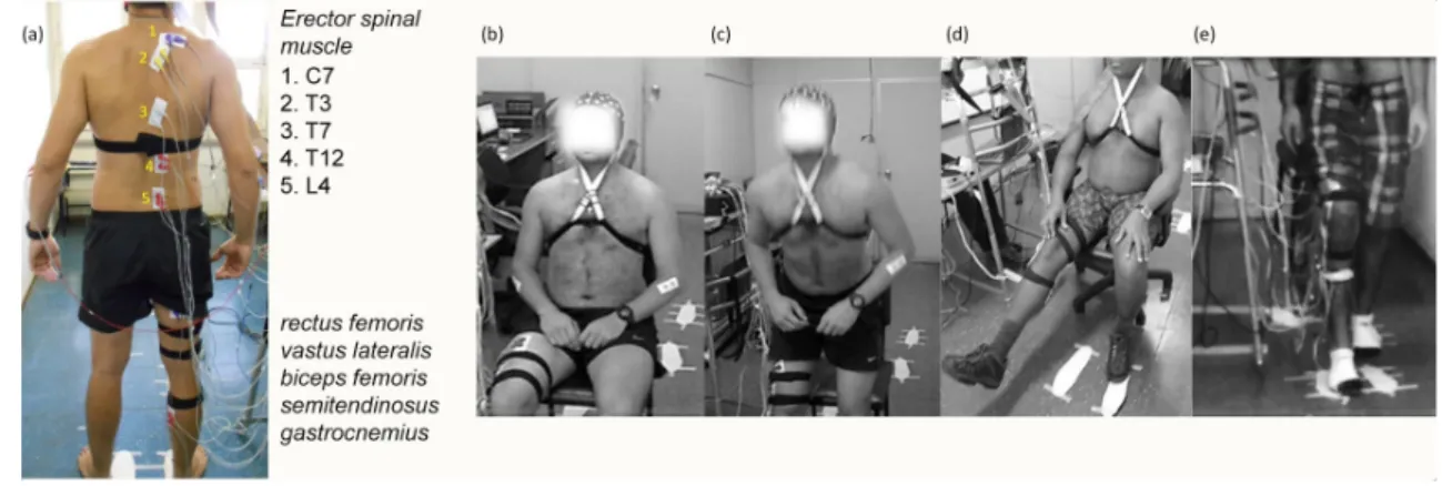
Ten healthy subjects (male 29.7 ± 4.0 years; height, 1.82 ± 0.07 m; weight, 84.5 ± 15.3 kg) without lower limb injury or motion deficits were selected to participate. A signal acquisition equipment (BrainNet BNT 36) was used to acquire sEMG signals (sampling rate of 400 Hz,
band-pass filter from 10 to 100 Hz) from the following muscles: rectus femoris, vastus lateralis, biceps femoris, semitendinosus, gastrocnemius, and erector spinae (ES) at levels C7, T3, T7, T12 and L4.
These were considered based on studies of lower-limb and trunk muscles activity during walking (Lee et al., 2015; Ceccato et al., 2009). The anatomical electrode location for each level was identified according to the literature (Lee et al., 2015; Sèze and Cazalets, 2008). The placement of the electrodes and the motion classes during the protocol are shown in Figure 4.
Two pairs of 10-mm Ag/AgCl surface electrodes were located on the right human body side, in bipolar configuration, on the muscles, with distance between the centers of each pair of 3–5 cm.
The position of the reference electrode was on the right leg. A goniometer and a footswitch also were used on the right leg to obtain the knee angle and the gait phases during walking. The subjects were cued through visual and sound stimuli with a period of 10 s to execute the following motor tasks: Stand-Up/Sit-Down (SU/SD), knee Flexion/Extension (F/E), two steps in walking (W), and Rest Stand-Up/Sit-Down (RSU/RSD). The motor tasks performed were repeated into two different experiments. Initially, a defined sequence composed of ten trials for each motor tasks was performed. Afterward, a random order, including six repeated trials for each motor task, was proposed to enhance generalization ability due to the fluctuation of sEMG. Each experiment had three tests of 20 trials (60 trials total), with rest of 3 min. The acquisition hardware was attached to a mobile platform in order to follow the subjects during the test. Thereafter, the sEMG data were processed off-line using Matlab 2014b. The HMIR system was validated for both lower-limb and trunk muscles. During the supervised learning, the classifiers were trained combining the first six trials from the sequential experiment with four Figure 3. Diagram of motion class F/E where the algorithm requires qmin (limit of knee extension), qmax (limit of knee flexion), downtime (time in which the joint stays in extension), and uptime (time in which the joint stays in flexion). Then, in each execution of the algorithm, the knee angle
(q) is required to generate a velocity profile according to F/E. A hyperbolic tangent function is applied to the profile in order to allow stopping and
trials from the random experiment. For validation, the remaining four and two trials from the sequential and random experiments were considered, respectively. Analysis for each subject S1 to S10 was performed
independently. To assess the effect of using muscular
groups of the trunk to accurately recognize lower-limb motions, statistically significant difference between these two muscular groups were evaluated using the Wilcoxon rank sum test, as the data did not pass the normality test (one sample Kolmogorov-Smirnov). The threshold for statistical significance was adopted at ρ< 0.05.
Controller test
Two healthy female subjects (25 years; height 1.60 m; weight 72 kg and 22 years; height 1.69 m; weight 70 kg) without lower limb injury or locomotion deficits were selected to participate. At the beginning of the experiments, the subjects were given 5 to 10 min to familiarize with ALLOR. The recording of the trajectories SU and SD was performed at the beginning of the experiment with the user employing a walker. The velocity profile F/E was generated by the algorithm previously shown in Figure 3, with qmin =20°, qmax =75°, downtime =0.5 s, uptime =5 s. To assist the gait, the gain G for initial contact, mid-stance, terminal stance and swing gait phases were: G1= 0.4 UW, G2 = 0.7 UW, G3 = 0.2 UW
and G4=0.1 UW, respectively, where UW is the user
weight in Kg.
A sequence of the motion classes was conducted to demonstrate the ability of the controller to perform the movements with the user employing a walker. Then, a test to evaluate the SC with the admittance adjustment during gait was realized with the subjects walking a distance of 10 m using ALLOR. Three trials were performed with the acquisition hardware attached to a
four wheel walker, in order to offer support and to have a mobile platform during the test.
To assess the effect of using ALLOR during experiments, data from the subjects, related to knee angle, torque, admittance modulation and gait phase were obtained. Then, maximum angle, maximum torque, stance phase percentage and gait cycle duration were analyzed.
Results
HMIR results
Results for the classifier SVM can be summarized in Table 1.
The average accuracy of classification using lower-limb muscles (LL) for siting movements (C1) was 83.2 ± 6.3% for all subjects, while for standing movements (C2) was of 76.2 ± 3.8%.
On the other hand, using trunk muscles (TR), the average accuracy was 71.0 ± 9.7% and 76.8 ± 5.9% for sitting and standing movements, respectively. It can
be observed a difference of 12.2% between results for
LL and TR muscles, for sitting movements, while for standing movements, average accuracies were very similar, with 0.6% of difference. In particular, for sitting movements, most of subjects showed slightly better classification using LL muscles, with difference from 4% up to 10% in comparison with TR muscles, except
subjects S8 and S10, whose differences were of 25%,
approximately. Subject S6 showed the highest accuracy for TR muscles, with 88.4 ± 8.3%, followed by S9 and S5, with 80.0 ± 9.1% and 79.9 ± 9.0%, respectively. Subjects S1-S4 showed the best performance using TR muscles, with accuracy > 80%. The lowest accuracy (65.6 ± 14.9%) was obtained on subject S10. The confusion matrix for the subject S6 is shown in the Figure 5 (a). Here, it can be noted the confusion between Rest Sit-Down (RSD) Figure 4. Placement of electrodes and the execution of the motion classes during tests. (a) electrodes position at cord and lower limb. The electrodes on the trunk are marked at the picture with numbers. (b)-(e) motion classes during tests: Rest in Sit-Down position (RSD), Stand-Up (SU), knee Flexion-Extension (F/E), and Walking (W), respectively. In order to both follow the subject during walking, and control the stride length, a mobile
and Stand-Up (SU) classes, with 18.3% of false positives for SU. On the other hand, for standing movements, it was found that five subjects showed an improvement
in accuracy using TR muscles, with up to 9.3% of differences in relation to LL muscles. Subject S1 achieved the highest accuracy (84.4% ±11.2). From this figure, it Figure 5. Classification results of the HMIR system. (a) Confusion matrix using trunk muscles of subject S6 for sitting movements (C1), and
subject S1 for standing movements (C2); (b) Accuracy dispersion among all subjects for each motion class using trunk and lower limb muscles,
respectively; (c) Accuracy (%) dispersion for the classification of C1 and C2 movements for trunk (TR) and lower limb (LL) muscles, respectively.
Boxplot depicts the median (red line), interquartile range (blue box) and maximal/minimal values (whiskers).
Table 1. Classification results using SVM for motion intention recognition.
Subject
C1 C2
LL TR LL TR
Mean (SD) Mean (SD) Mean (SD) Mean (SD)
1 74.2 (8.3) 66.9 (39.4) 79.7 (11.6) 84.4 (11.3)
2 80.9 (11.8) 71.3 (15.3) 75.7 (9.0) 82.1 (13.9)
3 86.0 (8.7) 77.7 (17.9) 77.4 (4.3) 83.7 (14.5)
4 73.3 (16.9) 62.8 (40.9) 70.7 (9.2) 80.0 (16.6)
5 89.1 (5.6) 79.9 (9.0) 73.0 (4.9) 69.6 (6.0)
6 92.9 (4.5) 88.4 (8.3) 82.5 (15.5) 76.1 (18.8)
7 77.5 (4.3) 66.6 (27.1) 78.0 (13.3) 77.4 (13.9)
8 83.6 (9.6) 59.7 (14.8) 69.5 (7.8) 77.8 (17.3)
9 89.4 (2.2) 80.0 (9.1) 77.5 (14.1) 71.2 (6.5)
10 84.7 (9.4) 56.5 (31.7) 77.8 (7.9) 65.6 (14.9)
Mean (SD) 83.2 (6.3) 71.0 (9.7) 76.2 (3.8) 76.8 (5.9)
Median 84.2 69.1 77.4 77.6
Range [73,3 - 92,9] [56.5 - 88.4] [69.5 - 82.5] [65.6 - 84.4]
can be noted the tendency of Sit-Down (SD) and Rest from Standing-Up (RSU) classes to be confused with walking (W), with false positives above 16%.
Figure 5 (b) shows the accuracy dispersion among all subjects for each one of the motion class considered in this study, using both TR and LL muscles. These results showed similar tendency to recognize most of motor tasks for both muscular groups. However, the performance using LL muscles was better than TR muscles. In both cases, the motor tasks RSD showed high dispersion in comparison to other tasks. RSU and SU showed the best performance, with median of 93.05% and 88.27%, respectively. However, the median of RSD for TR muscles (50.43%) was the lowest in relation to the other classes, being that S1 and S4 showed the lowest accuracies among other subjects (21.5% and 16.2%, respectively). A comparison between trunk and lower-limb muscles was carried out. It was observed no significant difference between lower-limb and trunk
muscles for both C1 (p = 0.0757) and C2 (p = 0.6776), for all subjects.
Figure 5 (c) shows the relation between accuracy and results for both classifiers (C1 and C2), and both muscular groups: trunk and lower-limb. On the other hand, a comparison of the muscular groups in relation to each one of the motor tasks was performed. From this results, it was observed no significance difference for the motor tasks SU, SD, W and RSU (p > 0.2890). The motor tasks F/E and RSD showed a significant difference (p < 0.0451) when using both muscular groups.
Controller
Figure 6 (a) shows the knee angle, knee torque and gait phase of subject S1 during the execution of the sequence RSU-SD-SU-W-RSU-SD-F/E-SU of motions classes (dashed line in red) using ALLOR.
From this Figure, during F/E (204s < t < 247s) the movement is executed according to the trajectory, except in the two points marked with k where the arrows are located. In these points, the user’s intention seems stopping the movement, and an increment of the knee torque was obtained, such as expected. The third arrow termed non-sequence in the RSU motion class (247s < t < 260s) indicates a motion class that is not possible to be executed, due to do not follow the motion class sequence after F/E. Here, the user finished the knee flexion and waited in SD position until a SU motion class activates the corresponding controller. This demonstrates the performance of the FSM controller to guarantee safety for the user. The maximum torque is presented during walking at the beginning of the knee flexion. During RSU and SD, the knee torque is approximately zero. On the other hand, to execute the sequence SU (128s < t < 140 s), the torque is around 4 Nm.
Regarding the gait phase information, the footswitch signal shows a consistence during the motion classes RSU, SD and F/E.
In SU, the gait phase presents a different pattern, and during W the signal allows recognizing 4 sub-phases.
Results from Figure 6 (b) demonstrates the efficiency
of the knee admittance modulation for SC assistance, where is possible to see the variation of the knee angle during gait. Here, the variation of the knee angle in time shows that the subject walked approximately with the same velocity, with a gait cycle duration for subject 1 of 3.93 ± 0.18 s and for subject 2 of 3.25 ± 0.07 s. Even though the footswitch signals provided a detection of 4 and 3 gait phases, the method was able to adapt the modulation of the gain in these periods and maintain the expected tendency.
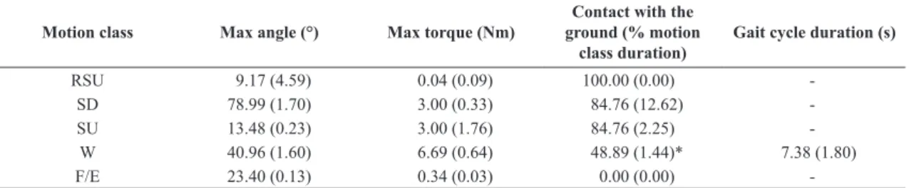
Table 2 shows the knee angle, torque and gait parameters obtained for subject S1.
No dangerous situation and no adverse effects were reported during or after the experiments, and all subjects completed the test. It was verified that the use of our system requires a therapist or assistant to mount the orthosis on the user. The total time required to this task is approximately 8 minutes with subjects
familiarized with ALLOR. When it is being used for the first time, more minutes are required, in order to adjust the length of leg and thigh segments along with hip angle adjustment. In this case, the total amount of time is from 20 to 25 minutes.
Discussion
Leg muscles have specific functions that provide movements of lower limbs, such as knee and ankle flexion-extension, walking, jump, among others. On the other hand, trunk muscles play an important role to control the posture in order to maintain the equilibrium during walking. ES muscles specifically have an active participation during lower limbs movements. Thus, this behavior of ES muscles may be a challenge for recognition system of lower-limb movements. Unlike lower limb muscles, trunk muscles may be preserved in some neurological cases, such as incomplete spinal cord injury and post-stroke. Therefore, these muscles may be exploited in a recognition system, in order to conveying control commands to the knee exoskeleton. We showed that leg and trunk muscles may be interchangeable to recognize some conditions as SU, RSU and W. However, different results were obtained for other conditions, such as F/E and SD. The system proposed here obtained higher values of standard deviation for trunk muscles, which shows a low participation of these muscles for the aforementioned conditions. However, an acceptable performance was obtained for three subjects: S5, S6 and S9 (ACC ≥ 79.9%). Thus, we consider that trunk muscles may be used as an alternative to conveying control commands for our exoskeleton ALLOR.
Furthermore, other techniques will be explored to improve the feature selection/extraction. In addition, the classifier setup can be optimized to increase the performance. We consider that the main finding of this study is that the trunk muscles provide enough information to recognize the following motion classes: stand-up, rest-in-stand position and walking. The results of this study also indicate that HMIR can be used to
Table 2. Gait parameters: angle and torque for the left knee joint while motion classes are performed with ALLOR for subject S1 (mean and standard deviation).
Motion class Max angle (°) Max torque (Nm)
Contact with the ground (% motion
class duration)
Gait cycle duration (s)
RSU 9.17 (4.59) 0.04 (0.09) 100.00 (0.00)
-SD 78.99 (1.70) 3.00 (0.33) 84.76 (12.62)
-SU 13.48 (0.23) 3.00 (1.76) 84.76 (2.25)
-W 40.96 (1.60) 6.69 (0.64) 48.89 (1.44)* 7.38 (1.80)
F/E 23.40 (0.13) 0.34 (0.03) 0.00 (0.00)
control a knee exoskeleton although on-line tests were not still developed.
Regarding the mid and low level control, it is presented the development of a strategy that allows assisting movements related to knee joint based on motion intention recognition. The control of the exoskelento ALLOR was developed and validated through the execution of the sequences sit-down, stand-up, walking and knee flexion-extension movements, synchronizing with a motion intention indicated by the user. A pilot test was undertaken, which confirmed the validity of the methodology.
The experimental results showed that the proposed controller can execute the movements of ALLOR commanded by the user’s intention. We confirmed that the controller provides reference pattern for the motion classes SD, SU and F/E, and proper torque for the motion classes considered here.
The motion SD results in a lower support torque for the knee compared with the motion SU, such as expected, which is also reported in previous studies (Fleischer and Hommel, 2006; Chen et al., 2015), which is due to the reduction of muscle activation during sit-down position.
Therefore, this controller can be used to help patients to re-learn motion patterns, such as the cases of the movements SD, SU and F/E. For F/E, the controller allows stopping the movement with the user motion intention detected by force, providing a simple solution to incorporate tasks with direct user’s interaction. Also, it is possible to incorporate variable knee resistance in the training, once the user has reached a certain level of progress with the admittance modulation. The controller also includes an assistance of the knee in Rest in Stand-Up Position by locking the joint to help to sustain the user’s weight, and using assisted walking devices, such as walkers or canes (depending on user condition) to reduce risks of falls.
The knee admittance was modulated during gait and knee assistance based on the stance control strategy achieved here. The duration of the stance phase represented around 50% of the gait cycle, as shown in Table 2. Previous studies reported that the stance phase during gait evaluation with healthy subjects using exoskelenton represents around 49% to 64% of the gait cycle, with the motion class SC (Kang et al., 2007; To et al., 2011). Then, the stance phase percentage obtained during gait with our method agrees with a gait analysis that considers SC, and allows a gait cycle closer at this condition. Furthermore, gait analysis with assistive devices tested with pathological cases, such as thoracic SCI spinal cord injury T9 (To et al., 2011), reports that the swing phase represents 25% of the gait cycle. In (Arazpour et al., 2016), a gait analysis using a knee–ankle–foot orthosis with a powered knee joint is reported, whose swing phase during evaluation with
poliomyelitis subjects represents 36% to 51% of the gait cycle. Then, in this sense, an important future task is to analyze the real-time adjustment of knee impedance in pathological gait.
During walking, the modulation of the admittance parameters was registered, and the method can be adapted even in cases with gait asymmetries. Although terminal stance phase was not detected in all trials, this is also reported in other studies, due the gait dynamic (Wentink et al., 2013; Agostini et al., 2014), the admittance modulation was able to generate a G pattern to obtain a SC performance as shown in Figure 5. It allows
adapting different impedances at the knee joint during
the phases stance and swing (Villa-Parra et al., 2017). For gait phase recognition in pathological cases, such as stroke survivors that present different footswitch patterns (Agostini et al., 2014), an alternative for gait phase detection is using data fusion considering the knee angle, initial movement from inertial sensors or sEMG signals to detect the gait phases (Lee et al., 2015).
Based on our experience obtained during the development of this protocol, the use of trunk muscles as myoelectric sources was more suitable than leg muscles, due to trunk signals were more comfortable to acquire. Thus, this system based on trunk muscles may be an alternative to control exoskeletons in cases where the lower-limb muscles are affected and their EMG activity is typically small (Sylos-Labini et al., 2014).
We consider that this study opens the research to develop other methods to be incorporated in rehabilitation protocols for patients with weakness and/or spasticity in their lower limb muscles for passive exercise therapy or gait rehabilitation with ALLOR. In fact, it is reported that using these devices can lead to a reduction in chronic pain and spasticity (Contreras-Vidal et al., 2016) and safety assistance in activities of daily living with suitable patient eligibility criteria (Miller et al., 2016). Additionally, for cases when the user requires a trajectory control during gait or a resistance training for knee flexion/extension in sit position, PI controller and admittance controllers can be implemented, respectively. The versatility of a low-level control allows to designing different therapies based on the user conditions and therapist advisory.
The mechanical adjustments for mounting ALLOR at the users require to be made based on their condition, and with physiotherapist guidance, in order to avoid risks in the intervention with the exoskeleton. Individuals with spasticity must be evaluated before, in order to define the therapy that will be executed with the exoskeleton.
Acknowledgements
This work has been supported by CNPq, CAPES and FAPES (Brazil), and SENESCYT (Ecuador). We thank the members of the ALLOR team for supporting the research and Flávia Loteiro for their support in the development of the protocol
References
Agostini V, Balestra G, Knaflitz M. Segmentation and classification of gait cycles. IEEE Trans Neural Syst Rehabil Eng. 2014; 22(5):946-52. http://dx.doi.org/10.1109/TNSRE.2013.2291907. PMid:24760911.
Arazpour M, Moradi A, Samadian M, Bahramizadeh M, Joghtaei M, Ahmadi Bani M, Hutchins SW, Mardani MA. The influence of a powered knee-ankle-foot orthosis on walking in poliomyelitis subjects: a pilot study. Prosthet Orthot Int. 2016; 40(3):377-83. http://dx.doi.org/10.1177/0309364615592703. PMid:26184037.
Arnos PM. Age-related changes in gait: influence of upper-body posture. Toledo: University of Toledo; 2007.
Cao J, Xie SQ, Das R, Zhu GL. Control strategies for effective robot assisted gait rehabilitation: the state of art and future prospects. Med Eng Phys. 2014; 36(12):1555-66. http://dx.doi. org/10.1016/j.medengphy.2014.08.005. PMid:25205588.
Ceccato J-C, Sèze M, Azevedo C, Cazalets J-R. Comparison of trunk activity during gait initiation and walking in humans. PLoS One. 2009; 4(12):e8193. http://dx.doi.org/10.1371/ journal.pone.0008193. PMid:19997606.
Chen B, Ma H, Qin L-Y, Gao F, Chan K-M, Law S-W, Qin L, Liao W-H. Recent developments and challenges of lower extremity exoskeletons. J Orthop Transl. 2016; 5(Supplement C):26-37.
Chen B, Ma H, Qin LY, Guan X, Chan KM, Law SW, Qin L, Liao WH. Design of a lower extremity exoskeleton for motion assistance in paralyzed individuals. IEEE International Conference on Robotics and Biomimetics (ROBIO); 6-9 Dec 2015; Zhuhai, China. New York: IEEE; 2015. p. 144-9. http:// dx.doi.org/10.1109/ROBIO.2015.7418758.
Chen G, Chan CK, Guo Z, Yu H. A review of lower extremity assistive robotic exoskeletons in rehabilitation therapy. Crit Rev Biomed Eng. 2013; 41(4–5):343-63. http://dx.doi.org/10.1615/ CritRevBiomedEng.2014010453. PMid:24941413.
Contreras-Vidal JL, A Bhagat N, Brantley J, Cruz-Garza JG, He Y, Manley Q, Nakagome S, Nathan K, Tan SH, Zhu F, Pons JL Powered exoskeletons for bipedal locomotion after spinal cord injury. J Neural Eng. 2016; 13(3):031001. http:// dx.doi.org/10.1088/1741-2560/13/3/031001. PMid:27064508.
Del Alma Espinosa AJ. Hybrid walking therapy with fatigue management for spinal cord injured individuals. Leganés: Universidad Carlos III de Madrid; 2013.
Fleischer C, Hommel G. Torque control of an exoskeletal knee with EMG signals. In: Proceedings of The 37th International Symposium on Robotics (ISR) and the 4th German Conference
on Robotics; 2006; Munich, Germany. Dusseldorf: VDI Ber; 2006. p. 79-82.
Fleischer C, Wege A, Kondak K, Hommel G. Application of EMG signals for controlling exoskeleton robots. Biomed Tech (Berl). 2006; 51(5-6):314-9. http://dx.doi.org/10.1515/ BMT.2006.063. PMid:17155866.
Hussain S, Xie SQ, Jamwal PK. Adaptive impedance control of a robotic orthosis for gait rehabilitation. IEEE Trans Cybern. 2013; 43(3):1025-34. http://dx.doi.org/10.1109/ TSMCB.2012.2222374. PMid:23193241.
Jiménez-Fabián R, Verlinden O. Review of control algorithms for robotic ankle systems in lower-limb orthoses, prostheses, and exoskeletons. Med Eng Phys. 2012; 34(4):397-408. http:// dx.doi.org/10.1016/j.medengphy.2011.11.018. PMid:22177895.
Kang SJ, Ryu JC, Moon IH, Kim KH, Mun MS. Walker gait analysis of powered gait orthosis for paraplegic. World Congress on Medical Physics and Biomedical Engineering; 2006 Aug-Sep 27-1; Seoul, Korea. Berlin, Heidelberg: Springer; 2007. p. 2889-91. http://dx.doi.org/10.1007/978-3-540-36841-0_730.
Karthikbabu S, Chakrapani M, Ganeshan S, Rakshith KC, Nafeez S, Prem V. A review on assessment and treatment of the trunk in stroke. Neural Regen Res. 2012; 7(25):1974-7. PMid:25624827.
Kiguchi K, Tanaka T, Fukuda T. Neuro-fuzzy control of a robotic exoskeleton with EMG signals. IEEE Trans Fuzzy Syst. 2004; 12(4):481-90. http://dx.doi.org/10.1109/TFUZZ.2004.832525.
Kim SY, Yang L, Park IJ, Kim EJ, Park MSJ, You SH, Kim YH, Ko HY, Shin YI. Effects of innovative WALKBOT robotic-assisted locomotor training on balance and gait recovery in hemiparetic stroke: a prospective, randomized, experimenter blinded case control study with a four-week follow-up. IEEE Trans Neural Syst Rehabil Eng. 2015; 23(4):636-42. http:// dx.doi.org/10.1109/TNSRE.2015.2404936. PMid:25850089.
Lee SW, Yi T, Jung JW, Bien Z. Design of a gait phase recognition system that can cope with EMG electrode location variation. IEEE Trans Autom Sci Eng. 2015; 99:1-11.
Louie DR, Eng JJ. Powered robotic exoskeletons in post-stroke rehabilitation of gait: a scoping review. J Neuroeng Rehabil. 2016; 13(1):53. http://dx.doi.org/10.1186/s12984-016-0162-5. PMid:27278136.
Mayor JJV, Costa RM, Frizera Neto A, Bastos TF. Dexterous hand gestures recognition based on low-density sEMG signals for upper-limb forearm amputees. Res Biomed Eng. 2017; 33(3):202-17. http://dx.doi.org/10.1590/2446-4740.08516.
Miller LE, Zimmermann AK, Herbert WG. Clinical effectiveness and safety of powered exoskeleton-assisted walking in patients with spinal cord injury: systematic review with meta-analysis. Med Devices (Auckl). 2016; 9:455-66. http://dx.doi.org/10.2147/ MDER.S103102. PMid:27042146.
Mizrahi J. Mechanical impedance and its relations to motor control, limb dynamics, and motion biomechanics. J Med Biol Eng. 2015; 35(1):1-20. http://dx.doi.org/10.1007/s40846-015-0016-9. PMid:25750604.
Sèze MP, Cazalets J-R. Anatomical optimization of skin electrode placement to record electromyographic activity of erector spinae muscles. Surg Radiol Anat SRA. 2008; 30(2):137-43. http://dx.doi.org/10.1007/s00276-007-0289-y. PMid:18183349.
Suzuki K, Mito G, Kawamoto H, Hasegawa Y, Sankai Y. Intention-based walking support for paraplegia patients with robot suit HAL. Adv Robot. 2007; 21(12):1441-69.
Swinnen E, Baeyens J-P, Meeusen R, Kerckhofs E. Methodology of electromyographic analysis of the trunk muscles during walking in healthy subjects: a literature review. J Electromyogr Kinesiol. 2012; 22(1):1-12. http://dx.doi.org/10.1016/j. jelekin.2011.04.005. PMid:21622008.
Sylos-Labini F, La Scaleia V, D’Avella A, Pisotta I, Tamburella F, Scivoletto G, Molinari M, Wang S, Wang L, van Asseldonk E, van der Kooij H, Hoellinger T, Cheron G, Thorsteinsson F, Ilzkovitz M, Gancet J, Hauffe R, Zanov F, Lacquaniti F, Ivanenko YP. EMG patterns during assisted walking in the exoskeleton. Front Hum Neurosci. 2014; 8:423. http://dx.doi. org/10.3389/fnhum.2014.00423. PMid:24982628.
To CS, Kobetic R, Bulea TC, Audu ML, Schnellenberger JR, Pinault G, Triolo RJ. Stance control knee mechanism for lower-limb support in hybrid neuroprosthesis. J Rehabil Res Dev. 2011; 48(7):839-50. http://dx.doi.org/10.1682/ JRRD.2010.07.0135. PMid:21938668.
Tucker MR, Olivier J, Pagel A, Bleuler H, Bouri M, Lambercy O, Millán JR, Riener R, Vallery H, Gassert R. Control strategies for active lower extremity prosthetics and orthotics: a review. J Neuroeng Rehabil. 2015; 12(1):1. http://dx.doi.org/10.1186/1743-0003-12-1. PMid:25557982.
Villa-Parra AC, Broche L, Delisle-Rodríguez D, Sagaró R, Bastos T, Frizera-Neto A. Design of active orthoses for a robotic gait rehabilitation system. Front Mech Eng. 2015; 10(3):242-54. http://dx.doi.org/10.1007/s11465-015-0350-1.
Villa-Parra AC, Delisle-Rodriguez D, Lima JS, Frizera-Neto A, Bastos T. Knee impedance modulation to control an active orthosis using insole sensors. Sensors (Basel). 2017; 17(12):2751. http://dx.doi.org/10.3390/s17122751. PMid:29182569.
Viteckova S, Kutilek P, Jirina M. Wearable lower limb robotics: a review. Biocybern Biomed Eng. 2013; 33(2):96-105. http:// dx.doi.org/10.1016/j.bbe.2013.03.005.
Wentink EC, Beijen SI, Hermens HJ, Rietman JS, Veltink PH. Intention detection of gait initiation using EMG and kinematic data. Gait Posture. 2013; 37(2):223-8. http://dx.doi.org/10.1016/j. gaitpost.2012.07.013. PMid:22917647.