N
N
A
A
Y
Y
A
A
N
N
N
N
A
A
G
G
E
E
S
S
H
H
N
N
A
A
Y
Y
A
A
K
K
Graduated in Biochemical Engineering
D
DE
EV
VE
EL
LO
OP
PM
ME
EN
N
T
T
O
OF
F
M
MI
IX
XE
ED
D
M
MA
AT
TR
RI
IX
X
M
ME
EM
MB
BR
RA
A
NE
N
ES
S
W
WI
IT
TH
H
M
ME
ET
TA
AL
L-
-O
OR
R
GA
G
A
NI
N
IC
C
F
FR
R
AM
A
ME
EW
WO
OR
R
KS
K
S
A
AN
N
D
D
I
IO
ON
NI
IC
C
L
LI
IQ
QU
UI
ID
DS
S
F
FO
OR
R
B
BI
IO
OG
GA
AS
S
U
UP
PG
GR
RA
A
DI
D
IN
NG
G
Dissertation for obtaining the Erasmus Mundus Master degree in Membrane Engineering
Advisor: Luísa Neves, Post - Doc Researcher, FCT-UNL Co-advisor(s): Isabel Coelhoso, Professor, FCT-UNL
João G. Crespo, Professor, FCT-UNL
Jury:
President: Prof. Isabel Coelhoso, Assistant Professor, FCT, UNL, Lisboa, Portugal Examiner(s): Dr. Vitor Alves, Assistant Researcher, ISA, UTL, Portugal
Prof. André Ayral, Professor, UM2, Montpellier, France
Prof. Karel Bouzek, Professor, VŠCHT, Prague, Czech Republic Prof. Patrice Bacchin, Professor, UPS, Toulouse, France
Member(s): Dr. Luísa Neves, Post-Doc Researcher, FCT, UNL, Lisboa, Portugal
N
N
A
A
Y
Y
A
A
N
N
N
N
A
A
G
G
E
E
S
S
H
H
N
N
A
A
Y
Y
A
A
K
K
Graduated in Biochemical Engineering
D
D
E
E
V
V
E
E
L
L
O
O
P
P
M
M
E
E
N
N
T
T
O
O
F
F
M
M
I
I
X
X
E
E
D
D
M
M
A
A
T
T
R
R
I
I
X
X
M
M
E
E
M
M
B
B
R
R
A
A
N
N
E
E
S
S
W
W
I
I
T
T
H
H
M
M
E
E
T
T
A
A
L
L
-
-
O
O
R
R
G
G
A
A
N
N
I
I
C
C
F
F
R
R
A
A
M
M
E
E
W
W
O
O
R
R
K
K
S
S
A
A
N
N
D
D
I
I
O
O
N
N
I
I
C
C
L
L
I
I
Q
Q
U
U
I
I
D
D
S
S
F
F
O
O
R
R
B
B
I
I
O
O
G
G
A
A
S
S
U
U
P
P
G
G
R
R
A
A
D
D
I
I
N
N
G
G
Dissertation presented to Faculdade de Ciências e Tecnologia, Universidade Nova de Lisboa for obtaining the master degree in Membrane Engineering
Development of Mixed Matrix Membranes with Metal – Organic Frameworks and Ionic Liquids for Biogas Upgrading
The EM3E Master is an Education Programme supported by the European Commission, the European Membrane Society (EMS), the European Membrane House (EMH), and a large international network of industrial companies, research centers and universities (http://www.em3e.eu).
Copyright @ Nayan Nagesh Nayak, FCT/UNL
A Faculdade de Ciências e Tecnologia e a Universidade Nova de Lisboa têm o direito, perpétuo e sem limites geográficos, de arquivar e publicar esta dissertação através de exemplares impressos reproduzidos em papel ou de forma digital, ou por qualquer outro meio conhecido ou que venha a ser inventado, e de a divulgar através de repositórios científicos e de admitir a sua cópia e distribuição com objectivos educacionais ou de investigação, não comerciais, desde que seja dado crédito ao autor e editor.
i
“If I have seen further than others, it is because I am standing on the shoulders of giants”
- Sir Isaac Newton
And they certainly were giants who let me climb their shoulders and stand there long enough to see a little further than what I had seen before. I pay a humble tribute by dedicating this work to them.
I express my heartfelt gratitude to my supervisor, Dr. Luísa Neves, Research Associate, Chemical and Biochemical Engineering Department at Faculdade de Ciências e Tecnologia, Universidade Nova de Lisboa, for her vision, motivation, encouragement, and moral support throughout this project.
I express my sincere thanks to my co - supervisors Prof. Isabel Coelhoso and Prof. João G. Crespo, Professors at Chemical and Biochemical Engineering Department at Faculdade de Ciências e Tecnologia, Universidade Nova de Lisboa, for their keen observations, critical judgement and invaluable advice at the right moment which helped me complete this project.
I also thank Hugo Andrade, Rita Ferreira, Ana Rute Ferreira, Carla Martins and Inês Meireles, for helping me with the experiments and giving me useful practical advice and on the whole making my work at DQ, FCT-UNL highly enjoyable. I am thankful to Prof. Vitor Alves, Professor, Instituto Superior de Agronomia, Lisbon, for his help with experiments regarding the mechanical properties.
I would like to sincerely thank Dr. Elena Vallejo, Chargée de Projets, UM2, France for bearing with us, being so kind and listening to all our problems for the last two years and helping us above and beyond her capacity on many occasions
I am also very grateful to all the professors and especially to the coordinator of the EM3E program Prof. André Ayral for his support and guidance throughout the entire master course.
I also thank all the faculty, research and administrative staff of UM2 - France, ICT – Prague and FCT-UNL- Portugal for providing the necessary support either directly or indirectly.
I would like to thank the European Union and the European Commission for organizing the Erasmus Mundus scholarship program without which I couldn’t have been able to do this course.
ii
Biogas is produced as a result of anaerobic degradation of organic matter and consists of approximately 60% methane and 40% CO2 and other impurities. Pure methane is a high calorific fuel with great commercial value. The presence of impurities reduces its combustion efficiency. Also in order to be transportable methane needs to be compressed which is not possible if CO2 is present. Thus it makes sense to upgrade biogas in order to enhance its commercial value. Biogas upgrading by membrane based gas separation processes offer a number of benefits over other gas separation technologies namely, low energy expense, small footprint and lack of mechanical complexity. Presently several membrane based processes are being applied for this purpose but have still not reached the commercial popularity of existing processes like Pressure swing adsorption or Water scrubbing. This is mainly because of lower permeability and selectivity of affordable membranes and hence lower throughput and productivity.
Currently several research efforts are being made to develop better membranes – one such type are mixed matrix membranes. Several additives/fillers could be added or dispersed in the matrix to make mixed matrix membranes, the most popular being inorganic molecules like zeolites and more recently, metal organic frameworks (MOFs). In parallel, several research efforts are focused on developing supported ionic liquid membranes (SILMs) - membranes impregnated with ionic liquid in pores which have shown promise for separation of both CO2/N2 and CO2/CH4 gas pairs. However, as the ionic liquid is retained in the porous support merely by capillary forces, these membranes are not stable for high pressure applications (e.g., separation of CO2/CH4).
In the present work attempts have been made to solve this problem by synthesizing ionic liquid incorporated dense Matrimid membranes. In such membranes the ionic liquid is impregnated inside a dense membrane by a physico-chemical interaction like cross-linking achieved by careful selection of polymerization environment i.e., the solvent and physical conditions. These membranes showed better hydrophilicity than neat Matrimid but lower puncture resistance. On incorporation of increasing levels of ionic liquid in the membrane (80% wt/wt of Matrimid) the CO2 permeability increased upto 36 barrer, which is better than that of neat Matrimid but not beyond the referenced Robeson upper bound cited in the literature. However the CO2/CH4 selectivity decreased to 7.5.
iii
permeability increased to 843 barrer. From these results it can be said that further studies with different MOF loadings and task specific ionic liquids could lead to discovery of better membrane for high performance CO2/CH4 separation for biogas upgrading.
iv
Contents
Acknowledgements ... i
Abstract ... ii
List of figures ... vi
List of tables ... vii
Abreviations ... viii
1. Introduction ... 1
1.1. Motivation ... 1
1.2. Goal and objectives ... 2
2. Literature Review ... 3
2.1. Biogas ... 3
2.2. Biogas Upgrading – Conventional methods ... 4
2.3. Membrane based biogas upgrading ... 5
2.4. Economics of biogas upgrading ... 14
3. Materials and Methods ... 17
3.1. Membrane preparation ... 17
3.2. Contact Angle ... 18
3.3. Scanning Electron Microscopy (SEM) ... 19
3.4. Mechanical Properties ... 19
3.4.1. Puncture test ... 19
v
4.1. Membrane Preparation ... 22
4.2. Surface Properties ... 22
4.2.1. Contact Angle ... 22
4.3. Scanning Electron Microscopy (SEM) ... 24
4.4. Mechanical Properties ... 30
4.4.1. Puncture test ... 30
4.5. Gas Permeability ... 32
5. Conclusions and Future Perspectives ... 36
6. References ... 38
7. Appendix ... I
7.1. Appendix I: Estimation of ... I
7.2. Appendix II: Gas Permeation Estimation and Pressure profiles ... II
vi
Figure No. Figure title Page
Figure 2.1 Biogas Lifecycle 4
Figure 2.2 Biogas upgrading systems in Europe (a) number; (b) overall capacity 6
Figure 2.3 Structure of Matrimid5218 9
Figure 2.4 Chemical structure of (a) [emim][Tf2N] and (b) [bmim][Tf2N] 10
Figure 2.5 Structural representation of (a) MOF 5 (b) Cu3(BTC)2 and (c) MIL 101 12
Figure 3.1 Scheme of method of membrane preparation 17
Figure 3.2 Schematic of a sessile drop, contact angle and the three interfacial tensions are shown 18
Figure 3.3 Puncture Test Scheme 20
Figure 3.4 Gas permeation setup; V1, V4 are inlet valves; V2, V3 are exhaust valves; PI1, PI2 are
the pressure transducers. The whole setup is placed in a thermostatic water bath
21
Figure 4.1 Contact angle for membranes with different IL contents 23
Figure 4.2 Scanning Electron Microscopy images of the Matrimid membranes with different IL % 27
Figure 4.3 SEM images of the Matrimid membranes with 50% IL and 20% MOFs - Cu3(BTC)2,
MIL101 and MOF-5 with Secondary electron emission (SE) and Back-scattered
electron emission mode (BSE)
29
Figure 4.5.1 CO2/ CH4 Permeability with increasing Ionic liquid content 33
Figure 4.5.2 Complete Robeson plot for CO2/CH4 with results from the current work 34
Figure 7.1 Feed and Permeate Pressure Profiles in the permeation cell I
Figure 7.2 Graphical representation of Eq 3.5.1 where the slope gives the value of I
Figure 7.3 Feed and Permeate pressure profile for CO2 with Matrimid membrane II
Figure 7.4 CO2 permeance in Matrimid membrane II
Figure 7.5 Stress Vs. Strain Curve for Matrimid membrane III
Figure 7.6 Stress Vs. Strain Curve for Matrimid +25% IL membrane IV
Figure 7.7 Stress Vs. Strain Curve for Matrimid 80% IL membrane IV
vii
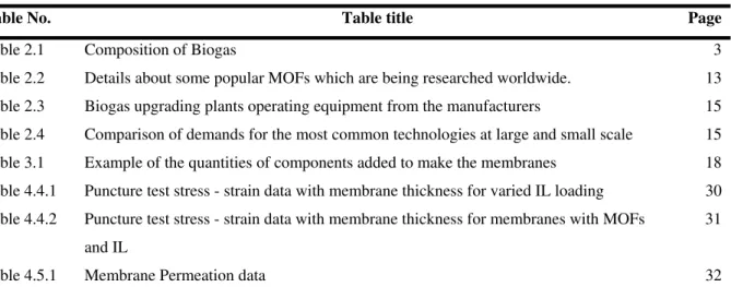
Table No. Table title Page
Table 2.1 Composition of Biogas 3
Table 2.2 Details about some popular MOFs which are being researched worldwide. 13
Table 2.3 Biogas upgrading plants operating equipment from the manufacturers 15
Table 2.4 Comparison of demands for the most common technologies at large and small scale 15
Table 3.1 Example of the quantities of components added to make the membranes 18
Table 4.4.1 Puncture test stress - strain data with membrane thickness for varied IL loading 30
Table 4.4.2 Puncture test stress - strain data with membrane thickness for membranes with MOFs
and IL
31
viii
αCO2/CH4 2 4
[B(CN)4] Tetracyanoborate
[BF4] Tetrafluoroborate
bmim 1-Butyl-3-methylimidazolium
CA Cellulose Acetate
CH4 Methane
CO2 Carbon dioxide
Cu3(BTC)2 Copper benzene-1,3,5-tricarboxylate
DTDA-DAPI poly(3,3’,4,4' benzophenone tetracarboxylic ‐ dianhydride diaminophenylindane)
emim 1-ethyl-3-methylimidazolium
EU European Union
6FDA 2,2'-Bis (3,4-Dicarboxyphenyl) Hexafluoropropane Dianhydride
FTIR Fourier Transform InfraRed Spectroscopy
GPU Gas Permeation Unit
H2 Hydrogen
H2O Water
H2S Hdrogen Sulfide
IL Ionic Liquid
MIL Chromium terephthalate
MMM Mixed Matrix Membrane
MOF Metal Organic Framework
N2 Nitrogen
PCH4 Permeability of methane
PCO2 Permeability of carbon dioxide
PDMS Polydimethylsiloxane
PI Polyimide
[PF6] hexafluorophosphate
PSA Pressure Swing Absorption
PVA Polyvinylacetate
RTIL Room Temperature Ionic Liquid
SILM Supported Ionic Liquid Membrane
[Tf2N] bis(trifluoromethylsulfonyl)imide
Tg Glass transition temperature
vbim 1-vinyl-3-butylimidazolium
ZIF Zeolitic Imidazolate Framework
THF Tetrahydrofuran
SEM Scanning Electron Microscopy
1
1.1. Motivation
Methane and hydrogen are two gases with great potential and both can be renewably produced
by biological systems. These gases are produced as an offshoot of waste degradation. However, they
are produced as part of a mixture and need to be cleaned or stripped. Biogas, for example, produced
as a result of anaerobic degradation of organic matter consists of approximately 60% methane and
40% CO2 and other impurities [1]. Pure methane is a high calorific fuel with great commercial value.
The presence of impurities reduces its combustion efficiency. Also in order to be transportable
methane needs to be compressed which is not possible if CO2 is present. Thus it makes sense to
upgrade biogas in order to enhance its commercial value.
In order to upgrade biogas, membrane based gas separation processes offer a number of benefits
over other gas separation technologies namely, low energy expense, small footprint and lack of
mechanical complexity. The first CO2 separation membrane introduced in an industrial process was
the anisotropic cellulose acetate membrane developed by Grace Membrane Systems in the late 1970s
[2]. A high-performance gas separation material requires both high permeability and high selectivity;
however, it is hard to achieve both at the same time. Dense polyimide membranes are well known
for their high CO2 selectivity. Matrimid is a commercially available polyimide material which is
popular because of its ease of polymerization and economical pricing. It is also inherently,
moderately selective and permeable to CO2 [3]. This aspect of Matrimid can be improved upon by
creating a hybrid or mixed matrix membrane with gas or molecule selective particles dispersed in the
polymer. Several efforts have been made on this front by dispersing gas selective zeolites and metal
organic frameworks (MOFs) in Matrimid to improve its performance [4, 5].
In the past two decades, ionic liquids (ILs) have become a research focus due to their unique
combination of properties such as negligible vapour pressure, tuneable solvation properties and high
ionic conductivities. More recently, ILs have been explored as new CO2 separation media, largely
due to their highly preferential solubility for CO2 over other gases such as N2 and CH4 [6, 7].
Previous studies using SILMs (Supported Ionic liquid membranes – membranes impregnated with
ionic liquid in pores) showed promise for separation of both CO2/N2 and CO2/CH4 gas pairs [8, 9,
10]. However, as the ionic liquid is retained in the porous support merely by capillary forces, these
membranes are not stable for high pressure applications (e.g., separation of CO2/CH4).
In the present study, a simple approach to solve the above mentioned problems has been
attempted by preparing ionic liquid incorporated dense matrimid membranes. In such membranes the
ionic liquid is impregnated inside a dense membrane by a physico - chemical interaction like
cross-linking achieved by careful selection of polymerization environment i.e., the solvent and physical
2 and dense gas separation membranes. They also show improved mechanical and thermal properties
in comparison to the former. Furthering these concepts, efforts have also been made to develop ionic
liquid incorporated mixed matrix membrane with dispersed metal organic frameworks (MOFs)
particles with the potential objective of using it for high performance biogas upgrading.
1.2. Goal and objectives
The primary goal of this work is to synthesize a mixed matrix membrane containing an ionic
liquid and MOF particles which can be used for separation of carbon dioxide from biogas to obtain a
stream of pure bio-methane.
In order to achieve this goal the tasks were divided into the following objectives:
• Standardization of polymerization conditions for chosen polymer i.e., Matrimid;
• Screening of suitable Ionic liquids and MOFs based on data available in literature;
• Synthesis of mixed matrix membranes with different ionic liquid loading;
• Selection of appropriate Ionic liquid loading based on permeation properties;
3
2.1. Biogas
Biogas production is a process which uses anaerobic conditions together with microorganisms
and organic substrates in order to produce a mixture of gases; mainly carbon dioxide and
bio-methane. Organic substrates that can be used as a feedstock are energy crops, manures, industrial
wastes, sewage sludge, and the organic fraction of municipal solid wastes. Biogas is produced
naturally via many processes such as rice paddies, marshes and ruminants. Biogas can also be
produced in engineered systems such as; anaerobic digestion, sewage plants and landfills. Table 2.1
shows the composition of the raw biogas.
Table 2. 1. Composition of Biogas [1]
Gas Percentage
Methane 50-75
Carbon dioxide 25-45
Water vapour 1-2
Carbon monoxide 0-0.3
Nitrogen 1-5
Hydrogen 0-3
Hydrogen sulphide 0.1-0.5
Oxygen Trace
The production of biogas is economically and environmentally beneficial as it involves the
conversion of biomass into methane and carbon dioxide. It is beneficial to remove methane and
carbon dioxide as they are both considered greenhouse gases which have a negative impact on the
environment. The produced biogas can be used for heat and/or power generation, vehicle fuel and
4
Figure 2. 1. Biogas Lifecycle [1]
There is an increasing demand for upgraded biogas, fuelled by an ever growing concern for the
environment, climate change and air qualities especially in the urban environment. The European
Union is predicted to be responsible for 21 % of the greenhouse gas emissions globally [12, 13].
Bio-methane production can be used to provide fuel and heat source to promote regional
development, as it is more eco-friendly than the extraction of fossil fuels. An important
consideration for implementing the use of bio-methane production is that the feedstock is available
all year around [14]. Raw biogas can be combusted in a boiler though it does have a lower calorific
value. However, it is necessary to reduce CO2 levels below 2 vol% from biogas because it has no
heating value and it causes corrosion in process equipment when in the presence of water (formation
of carbonic acid). Upgraded biogas, on the other hand, can be used as a vehicle fuel, material for the
chemical industry, reactor fuel for the heat and electricity generating industry or for injection to the
national gas supply grid. Though upgraded biogas can be used in many ways, raw biogas use is still
the most common option and the most economically viable [15].
2.2. Biogas Upgrading – Conventional methods
Upgrading essentially involves reduction of CO2 levels to the range of 2 – 5 % (by volume) in
stock biogas. There are several standardized and popular methods to do this on the European market.
The water scrubber and pressure swing adsorption being the most common currently, since both
methods are more technically matured [16]. Cleaning and upgrading technologies that are selected
for plants are dependent upon several factors, one of them being the gas quality required [16].
Organic Feedstock
Anaerobic Digestion Digestate
Upgrading
Vehicle Fuel Gas Grid
Injection
Power Plant
Combined Heat and Power
5 Water scrubbing is used to separate both CO2 and H2S from biogas owing to their higher
solubility in water than H2 and CH4. Generally, the biogas and water jet are fed to a packed column
(typically, high surface area plastic media) in countercurrent mode. The water cannot be recycled
[15]. Polyethylene glycol absorption is similar to the water scrubbing process, but with the water
replaced by a better suited solvent (e.g. The Lurgi Purisol process and UOP Selexol process).
PSA (Pressure swing adsorption) is a technology where gases are separated under pressure
which is dependent on their ability to penetrate the material and remove the unwanted
contaminant(s). PSA technology is very flexible and can absorb a broad range of contaminants in
gases or liquids [15] Zeolites (highly porous) are the most common commercial adsorbent which
acts as molecular sieves [14]. The absorbed gases are then desorbed from the zeolites by decreasing
the pressure, allowing regeneration [14], hence the name, Pressure swing adsorption. Other popular
adsorbents are activated carbon, carbon molecular sieves etc. that are suitable to separate a number
of different gaseous compounds from biogas.
Cryogenic separation is based on fractional distillation. The raw biogas is compressed in
multiple stages with intercooling which allow the gas to be further compressed each time. The
compressed gas is dried to avoid freezing in the following cooling process. The gas is cooled to
approximately -55 °C by heat exchangers. The pressure is then altered and the temperature is
decreased to -110 °C. The gas phase, which consists of more than 97% methane, is heated before it
leaves the plant [17, 15]. CO2 is separated by condensation either by lowering the temperature or
increasing the pressure.
Membrane separation processes for CO2 removal generally provide several advantages over the
above-mentioned conventional separation techniques including low capital cost, high energy
efficiency, ease of processing, simple process equipment, and relative ease to operate and control.
Polymeric membranes, such as UOP Separex cellulose acetate (CA) membranes, have already
proven to operate successfully for natural gas upgrading [4].
2.3. Membrane based biogas upgrading
Gas separation membrane systems have been widely recommended due to their simplicity,
modular nature, and attractive economics compared to more traditional separation technologies such
as pressure swing adsorption (PSA) and cryogenic distillation. The concept of membrane separation
is based on the principle that only selected components of a mixture of fluids are able to pass
through a barrier (i.e. membrane). The separation of a vapor/gas(es) mixture is driven by the
chemical potential (or pressure) difference of the components across the membrane. When a stream
6 acts as a ‘filter’ to selectively allow only some species to permeate to the downstream side to
produce a specific component rich permeate stream.
Membrane separation can occur under both wet and dry conditions depending on what
substances are being removed. The diffusion rate is dependent on partial pressure, membrane
thickness and the chemical solubility of the substance. There is low and high pressure separation,
gas-gas and gas-liquid separation [15].
Monsanto installed the first large-scale membrane systems (polysulfone) for hydrogen recovery
from ammonia purge gas and refinery tail gas streams in the early 1980’s. Air separation systems to
produce 95-99% N2 were introduced in the late 1980’s. These systems produce N2 for inerting fuel
tanks, controlled atmosphere packaging for produce, and many other applications. Membranes are
also used for natural gas and biogas purification (CO2, H2O, H2S removal), mainly with cellulose
acetate polymers. However, these materials only have CO2/CH4 selectivities of 12 to 15 under
typical operating conditions [18], well below the low-pressure mixed gas selectivity of ~ 30 for
dense membranes with zero permeate pressure [3]. Much of the decline in performance is due to
plasticization of the membrane by CO2 and heavy hydrocarbons.
Figure 2.2. Biogas upgrading systems in Europe (a) number; (b) overall capacity [12].
Figure 2.2., shows the number of a particular type of biogas upgrading system (a) and the overall
capacity of these systems (b) in the European context [12]. Membrane technology, despite being the
cheapest to install and maintain [2], is not quite as popular as other systems. Amine absorption 48 10 31 6 1 41 Water Scrubber
Physical absorption (organic)
Chemical absorption (organic)
7 processes dominate the acid gas removal market, but membranes would be preferable in many cases
if they can maintain good performance in the presence of aggressive feed streams [1]. The
development of stable membranes with high CO2/CH4 selectivities would significantly enhance the
competitive position of membranes relative to alternate technologies [18]. As of today, in
commercial applications of membrane-based CO2/CH4 separations, cellulose acetate polymers are
most commonly used.
In membrane based biogas upgrading, permeability is an important factor where carbon dioxide
and hydrogen sulphide can then pass through the membrane (fibre wall), while methane is retained.
The upgrading process remains at high pressure, so no further compression is needed before addition
to the gas grid [17, 15]. A shortcoming of membrane separation constitutes a conflict between high
methane purity in the upgraded gas and high methane yield around 92% [15].
Operation at high permeate pressures is desirable from a CO2 sequestration perspective, but it
means that the average CO2 concentration would be higher throughout the membrane, thus
increasing the chances of plasticization. Moreover, as the CO2 fraction in the feed increases, the
membrane economics become more favourable, if the membrane performance remains stable.
These problems could be dealt with effectively by using mixed matrix membranes but it is still
in a nascent phase of development from the viewpoint of large scale applications. Hence the scope of
the present study will be restricted to mixed matrix membranes for biogas upgrading.
Mixed matrix membranes (MMM) have initially been produced in dense polymeric films for the
purpose of gas transport facilitation through the membrane. The embedding of hydrophobic zeolites
in rubber polymers proved to improve alcohol permeability and selectivity in pervaporation
processes in the presence of water [19]. Similarly, MMM have been developed for gas separation
processes in which different types of polymers and rigid filler materials were used. In this case the
selectivity is achieved as a combination of the permeation rates of the desired gas through the
polymer material and through the filler material. Initially, molecular sieves have been incorporated
by dispersing zeolites in rubber polymers [20]. Also the dispersion of zeolites in glassy polymers has
been studied [21, 22, 23, 80]. More recently, metal organic frameworks and carbon nanotubes have
been used as dispersed material in the production of MMM for gas separation [24].
MMM materials combine the high selectivity of the filler materials with the low costs,
manufacturing ease and flow behaviour of membranes [25]. MMM are characterized by high fluxes
with low pressure drop, with a predominant convection-type of transport with the fillers acting like
selective channels. By combining the properties of the polymer and filler, high permeabilities and
8 The flexibility in preparing different geometries tailored for specific applications is a great
advantage of the MMM platform technology. An important factor for the MMM performance is the
particle loading. The particle loading controls not only the capacity, but it also greatly influences the
membrane forming process and the resulting structure. A main concern when producing MMM is to
guarantee that the polymer, solvents and additives are compatible with the particles, so that the
functionality will not be lost in the embedding process.
Usually, the main base material of an MMM is the polymer. Polymeric membranes are
commonly classified into rubbery and glassy polymeric structures. These are defined by the
temperature at which the amorphous polymeric material is used. When the amorphous polymeric
material is operated above the polymer’s glass transition temperature (Tg), it is referred as a rubbery
membrane. The Tg is a characteristic temperature which depends on the polymer structure and
chemistry and is also of strong relevance to penetrant transport properties. Rubbery membranes can
rearrange their structure on a significant time scale and are usually in thermodynamic equilibrium.
Usually, glassy polymers are operated below their Tg and actually never reach thermodynamic
equilibrium because the time scale of polymer chain rearrangement is extraordinarily long. This non‐ equilibrated condition leads to the formation of micro‐cavities within the polymer matrix due to the imperfectly packed polymer chains [26]. Glassy membranes have been studied widely in the
literature and provide better performance for the selective layer, because the more restricted
segmental motions in glassy polymers enhance ‘mobility selectivity’ compared to rubbery
membranes [27, 28].
Polyimides are selected as the membrane material to be studied in this thesis. The term
‘polyimides’ refers to heterochain polymers containing an imide group in the backbone. The
branched configuration inherent to the polyimide functional group allows many ring structures to be
included in the polymer backbone [29]. These ring structures make the backbone chains stiff and
result in a very narrow free‐volume distribution [30]. In general, these polymers exhibit very high glass transition temperatures (in the range of ~300 – 424 °C [30, 31]). This class of polymers has
been studied extensively over the past 60 years, due to their high thermal and chemical stability and
excellent physico‐mechanical properties in a broad temperature range, in areas of electronics, electrical engineering, aviation and membrane separation [30]. Polyimides have found considerable
industrial demonstration and significant commercial use by NKK Corporation Japan, Nitto Electric
Co., Du Pont and Ube Industries, in membrane separation areas including ultrafiltration, reverse
osmosis, hydrogen separation and recovery, helium purification and recovery, vapor separation and
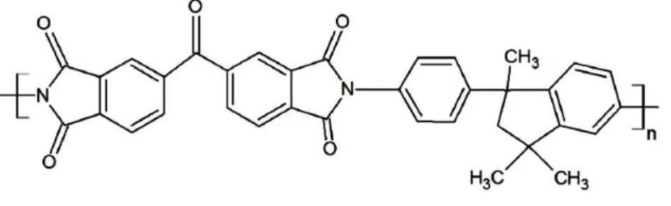
9 a trade name of Matrimid® 5218 (Figure 2.3) and a glass transition temperature of 313 °C [33]. It
exhibits a combination of selectivity and permeability for industrially significant gas pairs (e.g.
CO2/CH4 and CO2/N2) superior to other readily available polymers [34].
Figure 2. 3. Structure of Matrimid5218
From the perspective of CO2 removal from a gas stream using a membrane based method
probably the most successful additive could be considered to be ionic liquids. Ionic liquids (IL) are
defined as the liquids which solely consist of ions (cations and anions), as opposed to an ionic
solution, which is a solution of a salt in a molecular solvent and have a melting point of 100 C or
below. ILs which are liquid at room temperature are called room temperature ionic liquid (RTIL).
Ionic liquids have gained great attention in a variety of chemical processes due to their unique
properties such as non-volatility, non-flammability, high thermal stability and nature of tailoring
physical properties by selection of different cations and anions, and so on [35]. A potential
application of ionic liquids is for gas separation processes e.g. post combustion CO2 capture from
power plants and CO2 removal from natural gas/biogas etc. The non-volatile nature of ionic liquids
would not cause any contamination to a gas stream, and thus this feature gives ionic liquids a big
advantage over conventional solvents used for absorbing gases. To select an efficient ionic liquid for
use as a gas separation medium, it is necessary to know the solubility of the gas in the ionic liquid
phase. Reliable information on the solubility of gases in ILs is needed for the design and operation
of any possible processes involving IL [36].
Various experimental studies on gas separation processes using ionic liquids have been
conducted by researchers and are available in literature. A number of investigations have shown that
CO2 is remarkably soluble in several ILs. Figure 2.4 above shows two such popular ILs which have
10
Figure 2.4. Chemical structure of (a) [emim][Tf2N] and (b) [bmim][Tf2N]
Solubility measurements [7, 37], spectroscopic studies [38], and molecular simulations [7]
indicate that CO2 solubility in ILs depends primarily on the strength of interaction of CO2 with the
anion. Cadena et al.,[7] studied the mechanism of CO2 dissolution in imidazolium type ILs by
experimental and molecular modeling and found that the anions have larger impact on the solubility
of CO2. Anthony and co-workers made a comparison between different ionic liquids with same
cation and different anions to see their affinity to absorb CO2. They used three ionic liquids with
same cation i.e. 1-butyl-3- methylimidazolium ([bmim]) and three different anions i.e.
tetrafluoroborate ([BF4]), hexafluorophosphate ([PF6]), bis(trifluoromethylsulfonyl)imide ([Tf2N]) to
check the effect of anion on CO2 solubility. The results showed that the CO2 solubility is dependent
on the choice of the anion [6]. The ionic liquid with the [Tf2N] anion has a considerably higher
affinity for CO2 than either of the other two ionic liquids. The [bmim][ BF4] and [bmim][PF6] have
basically the same solubility, although the [bmim][ PF6] appears more soluble at higher pressures.
The solubility of CO2 in [bmim][ Tf2N] at different temperatures was also measured which showed
that the solubility decreases with increase in temperature and increases with increase in pressure
[39]. Lee et al.,[40] measured the CO2 solubility in [bmim][Tf2N] at different temperatures and
pressures. The solubility data measured is compared with the data reported by Anthony et al., [39].
The two sets of data were measured at slightly different temperatures. The results showed that the
two sets of solubility data are in good agreement qualitatively. At low pressures, the gas solubilities
appear linear as a function of the pressure but exhibited a nonlinear trend as the pressure increased,
at all four different temperatures [40].
Popularly, there are three systems which have been used for CO2 capture using ionic liquids.
Absorption system (absorber and stripper) is one of the most common techniques for gas purification
in which the flue gas is bubbled through the solvent (e.g. ionic liquid), the solvent will absorb the
gas of interest (e.g. CO2) from flue gas and the solvent is then regenerated in the stripper to use it (a)
11 again in the system [41]. The main disadvantage of this system is the large quantity of ionic liquid
required and the possible toxicity/environmental impact of the same.
Supported ionic liquid membranes (SILM) are the second technique that can be used for CO2
capture medium using ionic liquids. In SILM system, just the pores of a membrane are filled with
the solvent (e.g. ionic liquid). The more soluble gas is able to permeate across the membrane, while
the less soluble gas remains on the feed side. The flux of the gas across the membrane is affected by
the thickness of the membrane. A thinner membrane yields a higher flux, but the thinner the layer of
solvent, the quicker the solvent evaporates. But, due to non - volatile nature of ionic liquids this
problem can be eliminated in case of ionic liquids - SLM systems [42]. The limiting factor,
inhibiting the use of SILM is membrane instability at higher pressures wherein there is the tendency
of the ionic liquid to “leak” out of the membrane system into the product or feed stream. In order to
circumvent this problem there have been some studies carried out to make membranes with ILs in
the form of polymeric room temperature ionic liquid and ionic liquid gels. In a recent study, Hao et
al.[43], report very high performance in terms of permeability and selectivity for a membrane
synthesized using [vbim][Tf2N]/[emim][B(CN)4] and the filler metal organic network - ZIF8.
However, their mechanical and thermal stability is still not up to par with polymers.
In the third type of system the ionic liquid is incorporated in the membrane, possibly cross
linked into the dense matrix of the membrane. This type of system offers the advantage of SILM
overcoming the common disadvantages detailed above. In most cases it is found that due to the
incorporation of the ionic liquid, the properties of the base polymer in terms of permeability and
selectivity to a particular feed component and thermal and mechanical stability are enhanced. To
make such a system the polymerization process and environment have to be tweaked i.e., choosing
the right solvent and polymer is very crucial.
As discussed previously, inorganic fillers form a very crucial part of a mixed matrix membrane.
One such class of compounds which have recently become the focus of research are Metal Organic
Frameworks (MOFs). MOFs are crystalline compounds which consist of a metal ion or clusters
which are bound by coordinated bonds to rigid organic molecules. These organic molecules act as
linkers to the metal ions. The properties of the MOF depend on the choice of the metal and the
linker. They form one-, two-, or three- dimensional structures, and are porous in nature. These are
having unique properties, such as highly diversified structure, large range in pore sizes, high surface
areas, and specific adsorption affinity. Structures of some popular MOFs are shown below in Figure
12
Figure. 2. 5. Structural representation of (a) MOF 5 (b) Cu3(BTC)2 and (c) MIL 101
Usually MOFs are prepared under solvo-thermal or hydrothermal conditions. In this method
substances are crystallized from high temperature aqueous solutions at high vapour pressure. This
type of synthesis depends on the solubility of minerals in hot water under high pressure. Crystal
growth is performed in autoclave to provide high vapour pressure. The reactants are supplied in it
along with water. A temperature gradient is maintained at the opposite ends of the chamber. So, the
hotter end dissolves the reactants and the cooler end causes the seed crystals to grow. The table
below shows a list of popular mixed matrix membranes made with MOFs with some important
parameters which characterize their performance.
a) b)
13
Table. 2. 2. Details about some popular MOFs which are being researched worldwide.
MOF Polymer
Loading
%
(wt/wt)
Gases PCO2 αCO2/CH4 Commerci
al name References
Cu‐MOF ‐ ‐ CO2/CH4 ‐ 26 ‐ 44
Cu3(BTC)2
(HKUST 1)
Matrimid 30 CO2/CH4 1‐1.5
[GPU]
20‐30 Basolite
C300
4,5
ZIF 8 Matrimid 30 CO2/CH4 9.5[barrer] 43.6 Basolite
Z1200
4,45,46
MIL 53 Matrimid 30 CO2/CH4 1.4 [GPU] 29‐30 Basolite
A100
4,47
ZIF 69 Alumina ‐ CO2/CH4 103.4 [10− 9
mol m−2 s−1 Pa−1]
6.3 ‐ 48,49
ZIF 7 Pebax/PTSM P/alumina
34 CO2/CH4 41 [barrer] 44 ‐ 50,51
Cu TPA PVA 15 CO2/CH4 2.44
[barrer]
40.4 ‐ 52
MOF 5 Matrimid/al umina
30 CO2/CH4 20.2
[barrer]
44.7 53,54,55
Cu‐BPY‐HFS Matrimid 30 CO2/CH4 15.06
[barrer]
25.55 ‐ 56
ZIF 90 6FDA‐
DAM/MATRI MID
15 CO2/CH4 720/590
[barrer]
37/34 ‐ 57
Cu (HCOO)6 ‐ ‐ CO2/CH4 2.25*10‐
6
[mol/m2.s. Pa]
12.63 ‐ 58
NH2‐MIL‐53(AL) PSF 25 CO2/CH4 10 [barrer] 17 ‐ 59
AMIDE‐MIL53 6FO‐DMF (polyimide)
25 CO2/CH4 15 [barrer] 66 ‐ 60
*1 GPU = 7.5005 x 10⁻¹⁶ m·s-1·Pa-1
14 Many potential uses of MOFs include gas purification, gas storage, gas separation and
heterogeneous catalysis [56]. Because of strong chemisorption that takes place between electron
rich, odour-generating molecules and the framework that allows the desired gas to pass through it,
MOFs are promising for gas purification. These can store molecules such as carbon dioxide, carbon
monoxide, methane, and oxygen due to their high adsorption enthalpies. Gas separation can be
performed as they can allow certain molecules to pass through their pores based on size and kinetic
diameter. These can be used as catalysts because of their shape and size selectivity. Because of their
very porous structure, mass transport in the pores is not hindered. MOF as membrane material can
be used mainly for continuous membrane-based separations, membrane reactors etc. Along with
their various applications, many significant drawbacks are attached with MOFs. These are
mechanically and chemically unstable, due to their nature of bonding. Some of them are prone to the
formation of cracks and fractures and are extremely sensitive to moisture. Despite extensive
research, there still exist some challenges to fabricate low cost, crack free, continuous MOF based
membrane.
2.4. Economics of biogas upgrading
Economics is an important factor in determining if a particular technology is feasible and
profitable for an industry. Analysis of cost to gains has been performed for biogas production and
upgradading in the European context by several industries and commissions appointed by the EU.
According to Urban [16] the investment costs for a biogas upgrading plant treating 500 Nm3
biogas/h are on the average €1,000,000 while for a plant treating 2,000 Nm3 biogas/h the investment
costs are close to €3,000,000. Investment costs (€/Nm3 biogas) decrease as size of the plant
increases; for a plant treating 2,000 Nm3 biogas/h the costs are €1,500 /Nm3 and for a plant treating
500 Nm3 biogas / h the costs are on average €2,300 /Nm3 (Table 2.3.) De Hullu et al. [62] predicts
service/maintenance costs of around €50,000 annually including one annual internal and external
inspection of the plant. Urban [16] estimates that the maintenance costs are around 2 % of the
predicted capital costs and the water costs are assumed to be around €2 /m3
De Hullu et al. [62] does not mention scale but chemical absorption investment costs for carbon
dioxide and hydrogen sulphide removal are €869,000, PSA the cost is around €680,000, cryogenics
15
Table 2.3. Biogas upgrading plants operating equipment from the manufacturers [62]
Water Scrubbing PSA Chemical Scrubbing Membrane Separation Cryogenic Investment cost (€/year)
€ 265,000 € 680,000 € 353,000
-179,500
€ 233,000 –
749,000
€ 908,500
Maintenance
cost (€/year)
€ 100,000 € 187,250 € 134,000 -
179,500
€ 81,750 –
126,000
€397,500
Cost per
Nm3/biogas
upgraded
€ 0.13 € 0.25 € 0.17 – 0.28 € 0.12 – 0.22 € 0.44
De Hullu et al. [62] predicts the operational costs for chemical absorption for carbon dioxide and
hydrogen sulphide removal €179,500 annually, high pressure water scrubbing costs were €110,000
and PSA operational cost is €187,250. Cryogenics operational cost is €397,500 and membrane
separation is €81,700.
Table 2.4. Comparison of demands for the most common technologies at large and small scale [63]
Water Scrubbing Catalytic Absorption PSA Membrane Separation
Cryogenics Large Scale Small Scale
Gas quality High High High High High High High
Gas
Quantity
Volume
High High Medium Low Medium High Low
Compact Medium Medium No Yes No Medium Yes
Methane
Efficiency
High High Medium Low High High Low
Emissions Low Low Medium Medium Low Low Medium
Waste
Streams
Continuous Continuous Batch Batch Continuous Continuous Batch
16 Urban [16] stated that the substrate cost had a large influence on the cost of biogas production
and when the substrate prices are over €35 /tonne it can result in plants having a low income or even
a negative income.
The operating cost for biogas upgrading plants decreases as the size of the facilities increase.
Operating costs for a plant of around 500 Nm3 biogas / h are on average €220, 000 /y. As the
investment costs, also the operating costs per Nm3of biogas will be lower in larger upgrading units
(Table 2.4). Operating costs for a plant treating 500 Nm3 biogas / h are €440/Nm3 while for a plant
treating 2,000 Nm3 biogas / h the cost are about €340/Nm3 [16, 17].
Membrane technology, despite being the cheapest to install and maintain [2], is not quite as
popular as other systems. The development of stable membranes with high CO2/CH4 selectivities
would significantly enhance the competitive position of membranes relative to alternate
technologies.
Based on this premise, in the present study, we attempt to develop ionic liquid incorporated
dense Matrimid membranes. In such membranes the ionic liquid is impregnated inside a dense
membrane by a physico - chemical interaction like cross-linking achieved by careful selection of
polymerization environment i.e., the solvent and physical conditions [11]. In most cases such
membranes exhibit properties which are midway between SILMs and dense gas separation
membranes. They also show improved mechanical and thermal properties in comparison to the
former. Furthering these concepts, efforts have also been made to develop ionic liquid incorporated
mixed matrix membrane with dispersed MOF particles with the potential objective of using it for
17
3.1. Membrane preparation
Matrimid 5218 was obtained from Huntsman USA. Three custom synthesized MOFs were
obtained from our collaborators in the University of Porto - MOF-5, MIL101and [Cu3(BTC)2]. The
ionic liquid, 1- butyl - 3- methylimidazolium bis(trifluoromethanesulfonyl) imide, more commonly
known as [bmim][Tf2N] was acquired from IoLiTec Ionic liquid technologies GmbH, Germany.
Figure 3. 1. Scheme of method of membrane preparation
Figure 3.1 shows a schematic representation of the membrane making process. The membranes
were prepared by the method of solvent evaporation. 5% w/v solutions of Matrimid were prepared in
20ml glass vials by dissolving 0.5g Matrimid in 4.5 ml of dichloromethane. The additive solutions
(ionic liquid and/or MOF) were prepared in separate 20ml vials in dichloromethane. The additive
loading was determined by the following equation [4] (Eq. 3.1):
% % ∑ 100 … … . 3.1
The volume of ionic liquid required to make solutions of varied concentrations were calculated
on the basis of the density of the ionic liquid. The solutions were sonicated for 4 hours and agitated
for 24 hours separately on magnetic stirrers [2]. They were then mixed and agitated for 1 hour before
pouring them into flat bottomed petri dish and kept in desiccators for drying. Table 3.1., shows an
example of the component quantities to make neat Matrimid, 50% IL loaded and 50% IL with 20%
MOF loaded membranes.
Sonication in separate vials
-4 hours Matrimid (5%,
w/v))
Ionic Liquid (% of Matrimid)
MOF (% of Matrimid)
Agitation in separate vials
for 24 Hours
Mix all together for
1 hour
Pour on petri dish
Place in Desiccator for
Drying
18
Table 3. 1. Example of the quantities of components added to make the membranes
Vial Component/Membrane Neat Matrimid Matrimid with
50% IL
Matrimid with
50% IL and
20% MOF
1 Matrimid 0.5g in 9.5 ml
dichloromethane
0.5g in 4.5 ml
dichloromethane
0.5g in 4.5 ml
dichloromethane
2 Ionic Liquid 0 0.25g in 5 ml
dichloromethane
0.25g in 2.5 ml
dichloromethane
3 MOF 0 0 0.1g in 2.5ml
dichloromethane
3.2. Contact Angle
The contact angle () of a liquid drop on a solid surface is defined by the mechanical
equilibrium of the drop under the action of three interfacial tensions: solid-vapour (SV), solid-liquid
(SL) and liquid-vapour (LV) (Figure 3.2).
Figure 3. 2. Schematic of a sessile drop, contact angle and the three interfacial tensions are shown [64].
The equilibrium spreading coefficient (Ws) is defined by equation and can only be negative or
zero (Eq. 3.2.1):
… … . 3.2.1
Where Wa and Wc are the work of adhesion and work of cohesion respectively and can be
defined as
… … . 3.2.1
LV
SV
SL
Liquid
19
2 . … … . 3.2.1
The contact angle () was measured by sessile drop method. A drop of distilled water is
deposited manually on the membrane surface by a Pasteur pipette. Various photographs are acquired
by the software and the tangent is determined by fitting the drop shape to known mathematical
functions. The measurements are performed immediately after the drop falls on the surface. Multiple
replicates are performed and the mean contact angle is reported with its standard deviation.
3.3. Scanning Electron Microscopy (SEM)
The surface structure of the mixed matrix membranes prepared were analysed by the means of a
Jeol JSM-7001 F – Field emission scanning electron microscope, operated with an electron beam
intensity of 10kV. This microscope allows for the observation and characterization of heterogeneous
organic and inorganic materials at the scale of micro (10-6) to nano (10-9) meters. Cross section
imaging also can be done by using the “tilt” facility which allows the sample to be held at an angle
of 45 for analysis.
The principle of SEM involves the incidence of an electron beam on the sample surface
producing secondary electrons, backscattered electrons or retro-diffused x-rays which can be
analysed to obtain an image which is magnified over 200,000 times. In our case, the signal consists
of secondary electrons from which the surface image is constructed instantly. The primary electron
beam is mobile and scans the sample surface obtaining a complete image.
Sample preparation is an important part of this process as the material has to be clean cut
surfaces and must be a good conductor. In order to achieve this, 2 cm2 pieces of the sample were cut
in a liquid nitrogen environment to avoid distorting the material surface or cross section. The sample
is then impregnated with a thin layer of gold particles to make it a good conductor.
3.4. Mechanical Properties
Puncture tests were carried out using a TA-XT plus texture analyser (Stable Micro Systems,
Surrey, England). All mechanical tests were performed at ambient conditions. Three replicates of
each film were analysed.
3.4.1. Puncture test
Puncture tests were carried out by immobilizing the test samples (30x30 mm) on a specially
designed base with a hole of about 10 mm diameter. The samples were compressed at a speed of
20 (P) was expressed as the ratio of the puncture strength by the probe contact area as per equation
below (Eq 3.4.1).
… … . 3.4.1
Where P is the puncture stress (in Pa); FP is the force to the films (in N); and SP is the probe
cross sectional area (in m2).
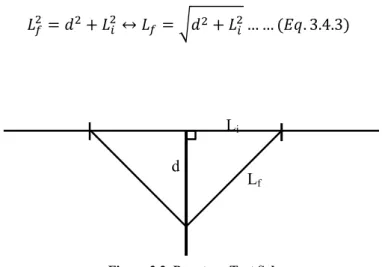
This test allows the determination of the strain by equation (Eq. 3.4.2)
100 … … . 3.4.2
Where εP is the puncture elongation; Lf is the final length (in m); and Li is the initial length (in
m).
The parameter Lf refers to the film elongation and it is calculated with base in the elongation
measured by the probe, d (Eq. 3.4.3). The Figure 3.3., below shows a representation of the test
calculation.
↔ … … . 3.4.3
3.5. Gas Permeability
To find the permeability of the membrane samples were cut into 2 cm diameter discs and their
thickness was measured using a micro-meter screw gauge (Braive Instruments, USA). The
experimental apparatus is composed of a stainless steel cell with two identical chambers separated
by the test sample. The permeability was evaluated by pressurizing one of the chambers (feed) up to
700 mbar, with pure methane or carbon dioxide followed by the measurement of the pressure change Li
Lf d
21 in both chambers over time, using two pressure transducers. The measurements were made at
constant temperature of 30 C ensured by immersing the cell in a thermostatic water bath (Julabo,
Model EH, Germany) as shown in the picture below.
Figure. 3. 4. Gas permeation setup; V1, V4 are inlet valves; V2, V3 are exhaust valves; PI1, PI2 are the
pressure transducers. The whole setup is placed in a thermostatic water bath.
The permeability was calculated by the method described by Cussler et al.,[65], with the
pressure data obtained from both compartments and by the software LabView and MS Excel by the
following equation (Eq 3.5.1):
1
ln 1ln ∆∆ … … . 3.5.1
Where pf and pp are the recorded pressures in the feed and permeate compartments respectively;
P is the gas permeability; t is the time; is the membrane thickness and is a constant called the
geometric parameter which is calculated for a given system by the following equation (Eq. 3.5.2):
1 1
… … . 3.5.2
Where Vf and Vp are the volumes of the feed and the permeate compartment respectively and A is
the membrane area. This parameter is calculated with a PDMS membrane and nitrogen as the test
gas using the reported permeability value of standard PDMS available, PN2/PDMS = 2.3 x 10⁻¹⁰ m2s-1.
The membrane gas permeability is obtained by the slope represented by the curve between
22
4.1. Membrane Preparation
Matrimid is soluble and polymerizes (on drying) in several organic solvents like
dichloromethane, THF, chloroform, etc., as reported in literature. However to obtain ionic liquid
cross linked membranes with Matrimid is slightly challenging. In the present work we experimented
with two different solvents – chloroform and dichloromethane. With chloroform it was observed that
when the ionic liquid concentration exceeded 15% (wt./wt. of Matrimid) a very porous membrane
was obtained after drying with ionic liquid residue remaining behind in the petri dish. However, with
dichloromethane stable dense membranes were obtained even with 90% ionic liquid (wt./wt. of
Matrimid) loading. It is unclear and beyond the scope of this study, whether this is the case only
with the ionic liquid used herein i.e., [bmim][Tf2N], or is a general phenomenon.
It was also interesting to observe that membranes prepared in the glass petri dishes, on drying in
the desiccator, were rigidly attached to the glass when ionic liquid concentration greater than 40%
(wt./wt. of Matrimid) was used. Hence Teflon plates were used to prepare membranes with higher
ionic liquid loading.
The membranes obtained after complete drying were homogeneous and flexible. The membrane
thickness varied from 70m to 400m based on the amount of ionic liquid added. The membrane
thickness increased with increased loading of ionic liquid. The Matrimid control membrane is
yellow in colour and completely transparent. As the ionic liquid loading was increased the
membrane became more opaque and flexible. On addition of MOFs the membrane acquired varied
colouration depending on the MOF used – green for MIL101, light blue for Cu3(BTC)2 and
whitish-yellow for MOF 5. Attempts were made to synthesize membranes with loading of 80% IL and 20%
MOF but it led to gel-like precursors and formation of defective membranes. Thus based on other
characteristics studied it was decided to proceed with membranes which are loaded with 50% IL and
20% MOF. These membranes were successfully synthesized.
4.2. Surface Properties
4.2.1. Contact Angle
Surface properties of a membrane give information about its hydrophilicity. The contact angle
increases with increasing surface hydrophobicity. This can help better understand the kinetic
interaction of the gases with the membrane surface.
23
Figure 4. 1. Contact angle for membranes with different IL contents
Despite the errors it can be seen from Figure 4.1 that the contact angle increases with increase in
ionic liquid % in the membrane till about 25% loading and then decreases. This means that the
hydrophobicity of the membrane surface increases with increasing IL % until 25% loading and then
the membrane becomes very hydrophilic. However, except for the membrane with 25% IL loading
none of the membranes is hydrophobic. For neat matrimid (0% IL) the data is in corroboration with
that reported in literature [20]. But it was contradictory for other samples as it was expected that the
hydrophilicity would increase with increase in IL doping.
The interaction of a polar molecule like CO2 with the membrane increases with increase in its
hydrophilicity. Thus it could mean that CO2 is more favourably adsorbed or permeated through the
membrane. This also means that the membrane has low affinity for a non-polar molecule like CH4.
Hence higher % IL could prove to be more feasible membranes for CO2 separation from methane.
It is also interesting to note that addition of MOF particles augmenting with the IL significantly
changes the hydrophilicity of the resulting membranes. In this case the membrane with MOF- 5
seems to have highest hydrophilicity compared to those with MIL 101 and Cu3(BTC)2.
It is important to note in this experiment that the associated gross error is significant since the
measurement is heavily dependent on the visual prowess and experience of the instrument operator.
In each trial several film samples and drops of fluid were used. The concluding result recorded was 50
55 60 65 70 75 80 85 90 95 100
Contact angl
e
(
24 for the trial considered by the operator to be the best. For best results the contact angle recorded in
the first 5 seconds was considered.
4.3. Scanning Electron Microscopy (SEM)
The scanning electron microscopy images depict the surface and cross section to better
understand the structure of the mixed matrix membrane with increasing ionic liquid concentrations.
The magnification used was 10000x for the surface and 2000x for the cross sectional view.
% IL Surface Cross Section
0%
25 15%
20%
26 30%
40%
27 80%
90%
Figure 4. 2. Scanning Electron Microscopy images of the Matrimid membranes with different IL %
It is apparent from the above Figure 4.2., that though the surface remained smooth with
increasing % IL the membrane porosity increased as can be seen in the cross sectional pictures. It
appears that there is a thin dense film on the surface. The membrane with 20% IL has an increased
number of surficial pores which can be due to accelerated drying of the membrane during synthesis.
Most of the membranes were homogeneous and any observable surface distortions can be attributed
28 MOF SEM
Mode Surface Cross-section
Cu
3
(BTC)
2
SE
BSE
MIL - 101
29 BSE
MOF -5
SE
BSE
Figure 4. 3. SEM images of the Matrimid membranes with 50% IL and 20% MOFs - Cu3(BTC)2, MIL101 and
MOF-5 with Secondary electron emission (SE) and Back-scattered electron emission mode (BSE).
Figure 4.3 shows scanning electron microscopy images of the Matrimid membranes synthesized
with 50% IL -[bmim][Tf2N] loading and 20% loading of three different MOFs – Cu3(BTC)2,
MIL101 and MOF-5. The samples were scanned in two modes – secondary electron (SE) emission
and back-scattered electron (BSE) emission. The back-scattered electrons are electrons of the
original electron beam (incident) reflected or scattered when they encounter the atomic nuclei of the
![Table 2. 1. Composition of Biogas [1]](https://thumb-eu.123doks.com/thumbv2/123dok_br/16496059.733564/16.892.327.575.402.662/table-composition-of-biogas.webp)
![Figure 2. 1. Biogas Lifecycle [1]](https://thumb-eu.123doks.com/thumbv2/123dok_br/16496059.733564/17.892.245.667.110.478/figure-biogas-lifecycle.webp)
![Figure 2.2. Biogas upgrading systems in Europe (a) number; (b) overall capacity [12].](https://thumb-eu.123doks.com/thumbv2/123dok_br/16496059.733564/19.892.157.734.615.988/figure-biogas-upgrading-systems-europe-number-overall-capacity.webp)
![Figure 2.4. Chemical structure of (a) [emim][Tf 2 N] and (b) [bmim][Tf 2 N]](https://thumb-eu.123doks.com/thumbv2/123dok_br/16496059.733564/23.892.241.673.103.361/figure-chemical-structure-emim-tf-n-bmim-tf.webp)
![Table 2.3. Biogas upgrading plants operating equipment from the manufacturers [62]](https://thumb-eu.123doks.com/thumbv2/123dok_br/16496059.733564/28.892.113.794.146.411/table-biogas-upgrading-plants-operating-equipment-manufacturers.webp)
![Figure 3. 2. Schematic of a sessile drop, contact angle and the three interfacial tensions are shown [64]](https://thumb-eu.123doks.com/thumbv2/123dok_br/16496059.733564/32.892.188.736.588.810/figure-schematic-sessile-contact-angle-interfacial-tensions-shown.webp)