ISSN: 1809-4430 (on-line)
_________________________
1 Engº Mecânico, Prof. Doutor, Engenharia Mecânica, IFSul/ Passo Fundo – RS, Fone: (0XX54) 3313 5045, [email protected] DESIGNING AND MANUFACTURING OF A SOYBEAN HARVEST RESIDUE PICKER Doi:http://dx.doi.org/10.1590/1809-4430-Eng.Agric.v35n6p 1053-1064/2015
RUBEM SCHÖFFEL1, WALTER BOLLER2, MÁRCIO WALBER3
ABSTRACT: Soy harvest matches seasons with shortage of dry matter supply for ruminant feeding in most Brazilian soy-growing areas. Agricultural machinery-producing companies must have
market perception, observing new opportunities and developing equipment to meet costumers’
needs. This paper aims to design, build, and test a device to collect soybean crop residues from the combine cleaning mechanism, consisting mainly of vegetable straw (chaff), and the other plant parts (stems) remain being deposited onto the ground. For equipment designing, we made use of the architectural design methodology proposed in the reference model for the agricultural machinery development process. The equipment was designed and built following the proposed methodology, then installed and put into operation in a John Deere 1165 combine. After initial testing and few adjustments, the device showed satisfactory chaff-collecting performance. The equipment consists of a screw conveyor assembled transversely to the combine and a centrifugal fan assembled on the side. The collected chaff is dumped into a trailer towed by tractor.
KEYWORDS: ruminant feeding, soy chaff, agricultural machinery designing.
PROJETO E CONSTRUÇÃO DE UM EQUIPAMENTO RECOLHEDOR DE RESÍDUOS DA COLHEITA DE SOJA
RESUMO: Na maioria das regiões produtoras de soja do Brasil, a colheita dessa cultura coincide com um período de escassez de oferta de matéria seca para a alimentação de ruminantes. As empresas produtoras de máquinas agrícolas devem ter a percepção do mercado, observando novas oportunidades e desenvolvendo equipamentos para atender às necessidades de seus clientes. O objetivo deste trabalho foi projetar, construir e testar um equipamento para coletar os resíduos da colheita de soja, provenientes do mecanismo de limpeza da colhedora, constituído principalmente pela palha dos legumes (palhiço), eis que as demais partes das plantas (hastes) continuam sendo depositadas no solo. A concepção do equipamento foi realizada utilizando a metodologia projetual proposta no modelo de referência para o processo de desenvolvimento de máquinas agrícolas. O equipamento foi projetado e construído seguindo a metodologia proposta, instalado e colocado em funcionamento em uma colhedora John Deere 1165, após os testes iniciais, e alguns ajustes, apresentando desempenho satisfatório na coleta do palhiço. O equipamento desenvolvido consiste em um transportador helicoidal montado transversalmente à colhedora e de um ventilador centrífugo instalado na lateral. O palhiço coletado é transferido para uma carreta agrícola, rebocada por trator.
PALAVRAS-CHAVE: alimentação de ruminantes, palhiço de soja, projeto de máquinas agrícolas.
INTRODUCTION
For NASCIMENTO et al. (2004), using agribusiness byproducts in nutrition is much important, particularly grains and prized food such as soy, corn, and wheat; for both human and animals other than ruminants. Besides increasing the availability of food for ruminants, the use of byproducts reduces costs and environmental pressure.
The world population is constantly growing, which has led to an increase in consumption and competition for food. Thus, new alternatives of food production must be developed to meet global demands. BACK et al. (2008) stated that globalization is a factor that has greatly increased competitiveness among companies, as well as information, goods, and food transport. For TOLEDO (1994), companies have taken the search for innovative products as the main strategy for their survival, longevity, and success. Thus, knowledge search for innovation has a key role in businesses maintenance, and consequently state and nation survival.
BACK et al. (2008) reported that to develop a product efficiently and effectively, you must know what to do, for whom to do it, when to do it, what to do it with, and how to do it. This organization (knowledge, methods, and tools) will be called design methodology, or product development methodology.
TOLEDO & SIMÕES (2010) asserted in a survey carried in São Paulo, focused on Product Development Management for Small and Medium Agricultural Machinery and Equipment Companies, which most of the medium-sized companies have no benefits from the main management technical support of the Product Development Process (PDP), generating numerous problems related to quality, time, and costs in the process. ZHOU (2012) studied the lean practices in Small and Medium Companies, discussing benefits and revealing factors that are able to prevent or hinder the implementation process of lean manufacturing. The study provides an understanding of strategies and their use in small organizations.
Agricultural production, as the root of most of the wealth generated in Brazil, has attracted the interest of governments and businesses. In this way, they are seeking solutions that enable the minimization of production costs and generate comfort for workers in this sector. Every business should have qualified technical assistance, especially regarding Product Development, such as conducting market research (TEIXEIRA et al., 2009), and consumer trends, to create truly long-lasting competitive advantages.
The study of BARBALHO & ROZENFELD (2013) demonstrated that the application of a reference PDP model might result in process improvement, reporting better indicators of time, cost and quality of the PDP.
Thus, according to TOLEDO (1994), corporations must remain competitive in face of its competitors in order to survive. This competition has led to the development of machinery, equipment, and tools which make life easier in the field and especially more profitable, making small farms viable. Currently, companies have been concerned mainly about developing machinery and equipment with high-tech embedded and large capacity. Industry should also look at small producers who have difficulty in acquiring and then in operating this equipment.
Given the above, the objective of this study was to develop and test a piece of equipment assembled to a grain combine, which is easy to operate and maintain, designed to collect the soybean chaff (straw from pods) simultaneously or after the harvesting operation.
MATERIAL AND METHODS
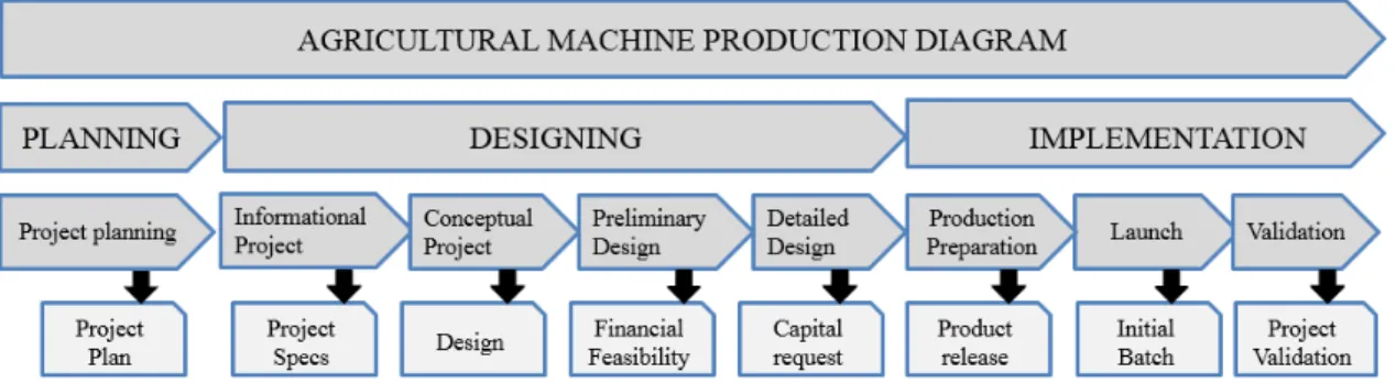
The reference model proposed by ROMANO (2013) for agricultural machinery development process (AMDP) is divided into three macrophases and eight phases, as seen in the diagram shown in Figure 1.
FIGURE 1. Reference Model for Agricultural Machinery Development Process (ROMANO, 2013). In the project-planning phase, according to ROMANO (2013), the consumer market size, the target audience and the selling price were estimated; it was observed the absence of chaff picking equipment. Manufacturing and approval standards of the equipment to be designed were also researched.
According to Oliveira et al. (2012), the planning stage involves the evaluations of micro-markets, selecting the machine design that meets the intended market.
At informal design stage, we set the project specifications, starting by the customers and/ or
users’ needs, which were dealt as customer requirements. Brainstorming was used for customers’
needs identification, and to prioritize project requirements, the House of Quality tool - QFD (Quality Function Deployment) was used. From this analysis, it was possible to define the most appropriate conception which could meet the customers’ and design’s requirements.
The conceptual design phase was intended for the agricultural equipment conception. At this stage, tasks that sought to establish functional structure of the agricultural equipment were carried out. This activity involved defining the machine global functions to be performed, as well as its sub-functions.
Once the functions had been determined, investigations on alternative functional structures were proceeded to select the most appropriate one. Then, alternative conceptions for the agricultural machine were developed. The morphological matrix was used to select the equipment functional structure.
Thus, after selecting the design, studies on the identification of feasible manufacturing processes (new or known, internal or external) were done. Prior to approval, the design was evaluated for compliance with the project scope.
The final layout was defined during the preliminary design stage. The preliminary design defines the most suitable dimensional layout for the equipment, which was obtained by refining alternative layouts, which resulted from an optimization, removing weaknesses and critical areas. At this stage, the equipment components dimensions, material, manufacturing process, among others were set to establish the final optimized layout and each item design.
The stage of detailed design was subdivided into prototype approval, completion of component specifications, and manufacturing plan detailing. After these updates, the prototype was built and field tests were conducted. To test the prototype, it was installed in a John Deere 1165 grain combine, with four straw walkers, evaluating its performance on chaff collection during soy harvest.
RESULTS AND DISCUSSION
In this section, we will present the results of the first two macrophases proposed by ROMANO (2013), which are regarded as Planning and Designing phases.
The equipment is consisted of two main parts. A rotating screw that aims to gather chaff from screens output and transport it to a suction pipe. And a turbine composed of a fan that sucks straw and drives it through a pipe up to the point where it will be deposited, which can be a tow coupled to a tractor or a big bag attached to the machine.
On soybean harvesting, it was noticed an opportunity of collecting part of the remaining plant residue for ruminants feeding. This way, a device or machine that could perform this operation was sought within the machinery and equipment market, and proved non-existent.
As proposed by OLIVEIRA et al. (2012), market size was taken into account. According to data from EMATER-RS (2011), 28775 dairy farms are potential consumers of this equipment throughout the region of Passo Fundo-RS, which covers 71 cities. Several dairy industries were found within the same region. One of the milk production bottlenecks is the food supply for dairy herd in times of forage shortage in warm season pastures. As most dairy farmers also have soy plantation areas, all these are part of the potential consumer market of this machine being designed. The market needs were observed and it was decided that a device to collect part of the soybean crop residues should be built.
According to OLIVEIRA et al. (2012), the selected project must be accepted on the intended market. Thus, the designed equipment should undertake residue collection parallel to grain harvesting and its price should be low to enable the acquisition by farmers.
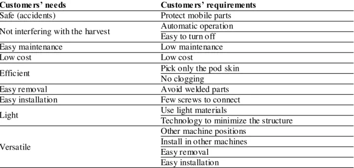
In a patent survey, a patent with the number BR8200095A was located, with publication date 05.11.1982 and depositor Schneider & Deboni Ltda. (BR/RS). This patent describes a device assembled to a grain combine titled "Soy straw bagger", which consists of a rotating screw and a vane lift that transports soy residue to a platform where a person handles the straw into bags. This bagging process during harvesting exposes operators to an unhealthy environment due to the presence of dust, solar radiation and noise. Furthermore, the "soybean straw bagger" resulted in low operational crop yield due to difficulty in residue bagging. The van type elevator has restrictions on straw volume to be transported, not allowing transport of the amount generated in the combine, in addition to frequent stoppages due to accumulation of material in the elevator ends caused by stems. TABLE 1. Transformation of customers’ needs (internal and external) into customers’
requirements.
Customers’ needs Customers’ requirements
Safe (accidents) Protect mobile parts
Not interfering with the harvest Automatic operation Easy to turn off
Easy maintenance Low maintenance
Low cost Low cost
Efficient Pick only the pod skin
No clogging
Easy removal Avoid welded parts
Easy installation Few screws to connect
Light Use light materials
Technology to minimize the structure
Versatile
Other machine positions Install in other machines Easy removal
In the information design, customer needs have been raised (external and internal), which
were transformed into customers’ requirements, giving rise to the project requirements. To collect this information (needs), we used a brainstorming method from which a list of customer needs emerged, being subsequently turned into requirements, as presented in Table 1.
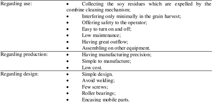
Next, the list was analyzed and project requirements were developed, being classified according to use, production, and design, as presented in Table 2.
TABLE 2. Customers’ needs classified in use, production, and design.
Regarding use: Collecting the soy residues which are expelled by the combine cleaning mechanism;
Interfering only minimally in the grain harvest;
Offering safety to the operator;
Easy to turn on and off;
Low maintenance;
Having great outflow;
Assembling on other equipment. Regarding production: Having manufacturing precision;
Simple to manufacture;
Low cost. Regarding design: Simple design.
Avoid welding;
Few screws;
Roller bearings;
Encasing mobile parts.
With the aid of the House of Quality tool - QFD (Quality Function Deployment), the project requirements were ranked in a priority and importance order, acquiring measurable characteristics. Thus, we could obtain the design that best met the project requirements.
By applying the proposed methodology, we could achieve a hierarchy of project requirements. The main equipment requirement is functioning coupled on different machines (being versatile). The second is to not interfere with the harvest, i.e., turning off easily in case of non-operation.
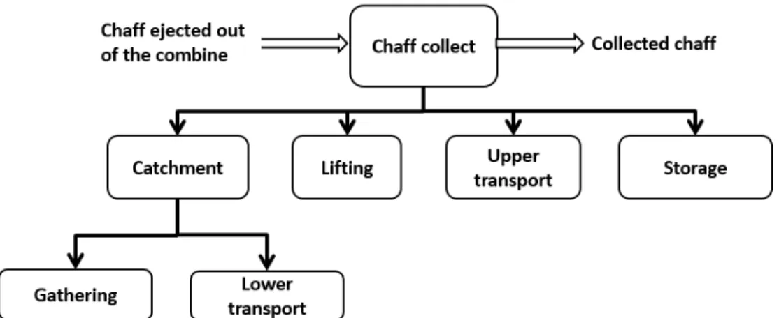
At the conceptual design, we used a functional analysis to build the functional structures of agricultural machine, with the purpose of determine its overall function and impact on partial (sub-functions) and elementary (sub-sub(sub-functions) functions, considering the inputs and outputs of energy, material, and signal.
FIGURE 2. Global function and equipment sub-functions.
After defining the overall function and sub-functions, combination of possible solutions were made using a morphological matrix, as shown in Table 3, and the best solutions were highlighted and then adopted in the project development.
TABLE 3. Morphological matrix, design possible combinations, and chosen path.
Sub-function A B C D
Picking Gravity Collection box Air Belt
Lower
transportation Gravity
Rotating
screw Air Belt
Lifting Rotating screw Lift Air Belt
Higher transport Belt Rotating screw Air Gravity
Storage Deposit attached to the combine Big bag Tow attached to the machine Tow attached to the tractor
Collection box and rotating screw were chosen to perform material picking and lower transportation; they were simple and efficient solutions, as they require low and simple maintenance, have a high-capacity transport, and hardly ever are "clogged". The collection box was manufactured using only metal plate. This choice is justified because it is not possible to install large components in the back of the machine, as these would prevent access for cleaning mechanism regulations. Yet the rotating screw was chosen to carry the chaff, once it forcibly leads it to the suction tube, which prevents local accumulation or "clogging”.
The choice of air for chaff lifting and transportation is justified because the fan is versatile, easy to install, has low maintenance and cost and yet provides disintegration of the whole soy stem, which might come together with chaff, making all the following operations easier.
The chaff storage can be performed in two ways, in a farm tow pulled by a tractor and by depositing the material into big bags attached to the machine. The first solution was chosen due to the existence of a tow tractor in most farms. The second solution was discarded because a construction based on the combine would be needed to provide support.
Thus, this phase was concluded by defining the equipment design, which will feature a low rotating screw which has a coupled collection box, and a fan that will act on lifting and higher transportation, using air as a conveyor.
The equipment was built by observing the functions defined at the conceptual design (Figure 2). In order to meet these functions, the chosen prototype layout was divided into two parts: first picking and lower transportation, being called rotating screw; and then lifting and higher transportation, which was named turbine. Storage sub-function was made by a farm tow pulled by tractor.
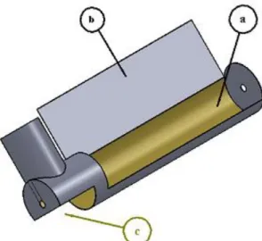
Figure 3 displays the rotating screw design, in which the main parts are composed of tube and spiral, which are highlighted in Figures 4 and 5, respectively.
FIGURE 3. Rotating screw.
The rotating screw tube (Figure 4) was designed to receive collected material. Therefore, its upper part is opened in the middle of its diameter (a), receiving an extension by means of a flat metal plate on one side, to perform the collection box function (b). The rotating screw tube has an opening at the bottom (c) to facilitate chaff flow when it is sucked, since the material may contain some soybean rods that could cause "clogging" on the location.
FIGURE 4. Rotating screw tube, (a) top opening of the rotating screw tube, (b) side flat plate, (c) side opening of the rotating screw tube.
FIGURE 5. Rotating screw spiral.
Placing the rotating screw on the back of the combine below the screens’ output should prevent chaff flow obstruction for two reasons. First, because it must be kept an access room for adjustments and inspections of the cleaning mechanism. Second, because grain cleaning is also performed by means of the airflow that removes chaff. Part of the chaff material will not be collected by the equipment and will remain deposited on the soil. This loss will cause a drop in chaff collection efficiency, which must be kept to a minimum level. This loss should be considered as source of nutrients for forthcoming crops.
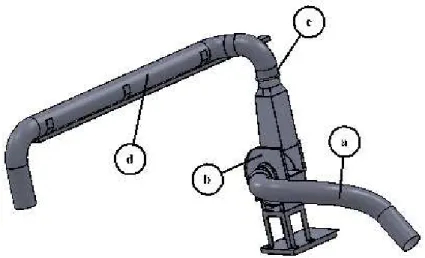
The turbine design, shown in Figure 6, was composed of a suction pipe (a), casing a nd centrifugal fan (b), lifting tube (c), and upper transportation tube (d). The upper transportation and suction tubes have a diameter of 20.32 mm and are made of flexible PVC (polyvinyl chloride), once this material allows forming smoother curves, enabling better inner airflow.
The centrifugal fan, which has a diameter of 570 mm, is manufactured with four straight blades of steel sheet (Figure 7) and is intended to suck chaff and transport it to storage room. The fan blades, due to their rotation and inertia, also break soybean stems entering the equipment, which facilitates transportation into the tube, and provides smaller storage volume.
FIGURE 7. Fan.
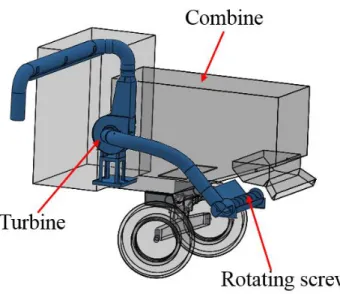
Figure 8 shows the final equipment layout, in which the turbine was installed on the side of the combine, near the pulleys that drive the straw walker. At the axis of these pulleys, another pulley that drives the turbine was installed, which rotates at a speed of 2400 revolutions per minute (rpm). The rotating screw is driven by a pulley that is fixed on the straw walker axis, and two supports, two bearings, an axis, and two pulleys were placed on the combine chassis to bring power
to the other side of the combine. The rotating screw in the combine is powered, and “V” belts make
all transmission of power between the axes.
FIGURE 8. Final Layout.
The main activities developed in the preliminary draft are preliminary and detailed layout preparations and drawings. As a result, we can define the final layout of the product design.
The fifth and last stage is the detailed design, which aims to fix the layout, shape, dimensions, and thresholds of all components. The drawings with complete specifications were executed, but were not displayed, because the main objective of this study was to develop a functional structure for the equipment and verify its operation.
(a) (b)
FIGURE 9. View of the opening on the rotating screw tube bottom, closed (a), material accumulation on the rotating screw tube bottom (b).
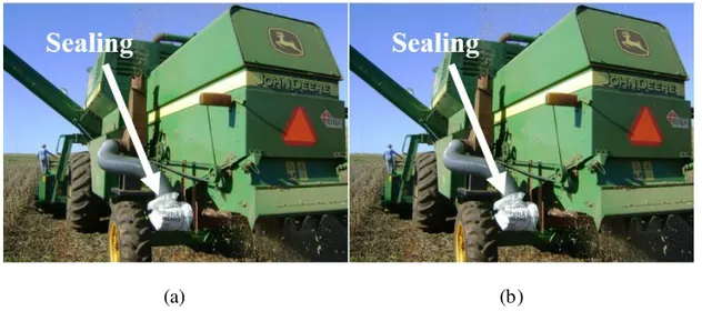
The prototype was installed and put into operation (Figure 10) and collected 952 kg ha-1 of chaff in a crop yield of 2868 kg ha-1.
FIGURE 10. Prototype in operation.
For meeting the first requirement, which is versatility, the equipment should collect chaff regardless of combine. For this, a device has been developed to enable turbine coupling to a tractor (Figure 11a). When triggered by power take-off, in this configuration, the turbine works vacuuming the ground chaff and transferring it to an attached tow trailer (Figure 11b).
(a) (b)
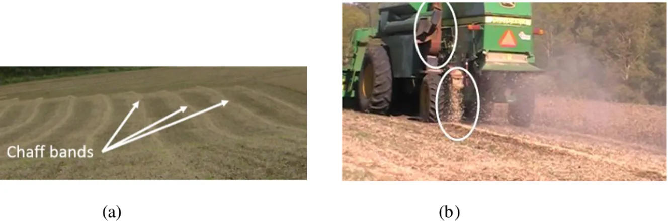
Chaff must be placed along bands on the soil to be collected. Therefore, the rotating screw is used to deposit the chaff onto bands on the ground (Figure 12). The turbine will remain attached to the combine (Figure 12b); however, during the harvest, it will remain off. This procedure might be
useful when chaff’s humidity is greater than the hay point (80-90% dry matter, according to PACHECO et al., 2014) or in case of unavailability of a tractor operator to collect chaff concurrently with the harvest.
(a) (b)
FIGURE 12. Chaff bands on the ground (a); rotating screw depositing chaff into bands (b). CONCLUSIONS
The prototype was built following the proposed methodology, and it could be installed and operated in a soybean grain combine. In this configuration, chaff is deposited into a coupled trailer towed by a tractor.
Alternatively, collected chaff may be deposited along bands on the ground, through the installation of a rotating screw in the combine and, subsequently, with the turbine assembled on a chassis coupled to a tractor, being driven by its power and it works sucking the chaff from the ground and depositing it into a tow trailer.
REFERENCES
BACK, N.; OGLIARI, A.; DIAS, A.; SILVA, J. C. Projeto integrado de produtos. Barueri: Ed. Manole, 2008.
BARBALHO, M. C. S; ROZENFELD, H. Modelo de referência para o processo de
desenvolvimento de produtos mecatrônicos (MRM): Validação e resultados de uso. Gestão & Produção, São Carlos, v.20, n.1, p.162-179, 2013.
EMATER-RS. Jornal O Nacional. Passo Fundo, v.24.824, 15 set 2011.
NASCIMENTO, H. T. S.; NASCIMENTO, M. P. C. B.; RIBEIRO, V. Q.; ARAÚJO NETO, R. B. Subprodutos da agroindústria da soja na alimentação de ruminantes. Teresina: Embrapa, 2004 (Circular Técnico, 37).
OLIVEIRA, A. S.; DALLMEYER, A. U.; ROMANO, L. N. Marketing in the pre-development process of agricultural machines: a reference model. Engenharia Agrícola, Jaboticabal, v.32, n.4, p.745-755, 2012.
PACHECO, W. F.; CARNEIRO, M. S. S.; PINTO, A. P.; EDVAN, R. L.; ARRUDA, P. C. L.; CARMO, A. B. R. Perdas fermentativas de silagens de capim-elefante (Pennisetum purpureum Schum.) com níveis crescentes de feno de gliricídia (Gliricidia sepium). Acta Veterinaria Brasilica, Mossoró, v.8, n.3, p.155-162, 2014.
TEIXEIRA, S. S.; MACHADO, A. L. T.; REIS, A. V.; OLDONI, A. Caracterização da produção agroecológica do sul do Rio Grande do Sul e sua relação com a mecanização agrícola. Engenharia Agrícola, Jaboticabal. v.29, n.1, p.162-171, 2009.
TOLEDO, J. C.; SIMÕES, J. M. S. Gestão do desenvolvimento de produto em empresas de pequeno e médio porte do setor de máquinas e implementos agrícolas do Estado de SP. Gestão & Produção, São Carlos, v.17, n.2, p.257-269, 2010.
TOLEDO, J. C. Gestão da mudança da qualidade de produto. Gestão & Produção, São Carlos, v.1, n.2, p.104-124, 1994.