Abstract — In order to achieve a better performance, the
time management techniques are used in most departments of an organization, in the production areas especially. However, the time management techniques also play an important part in the design and development stage of a new product. Thus, at this early stage, there are used the CAD systems (Computer Aided Design). This paper focuses on a specific example of improved process on the design phase of a new product. The nowadays CAD systems allow us to perform and standardize the design processes even at an early stage when new concepts are developed. Due to these advantages, the future benefits are easy to be recognized and exploited at any level. In this case, the most important benefits are the designing time and quality. This example can also be considered a tool of quality management because the CAD-systems allow the user to work accurately and without generating confusions.
Working with parameters even in design phase, allows the designer to create the ideal pattern-model as a basis for any other new part of the same pattern-model category.
By developing this pattern-model, we aim to avoid the development of a new part (single component) when a new project requires it. Instead, we will use the pattern-model from the same category which the outer tube is part of in this paper.
Index Terms—CATIA, Parameter, Programming,
Standardization
I. INTRODUCTION
T the moment, within the Technical Department of a multinational organization which deals with the design and manufacturing of shock absorbers for road vehicles, the engineers use design software such as: ME10 and Autocad for two dimensional (2D) design, and CATIA (Computer Aided Three dimensional Interactive Applications) for three dimensional (3D) design.
Manuscript received December 07, 2015; revised December 07, 2015. This work was supported in part by Alexandru-Marcel MOLDOVAN, Mihail Aurel Î U from Lucian Blaga University of Sibiu Romania and Niculae Ion MARINESCU from Politehnica University of Bucharest.
Alexandru-Marcel MOLDOVAN is Ec. Sc.D. Student at “Lucian Blaga” University of Sibiu and is the manager of the Technical Department from ThyssenKrupp Bilsten Compa S.A. from Sibiu (e-mail: [email protected]).
Mihail Aurel Î U is Professor at “Lucian Blaga” University of Sibiu (Faculty of Engineering) and is Director of the Intellectual Property Department of the University and Director of the European PATLIB Centre (corresponding author to provide phone: +40269430110, e-mail: [email protected]).
Niculae Ion MARINESCU is Professor at “Politehnica” University of Bucharest.
It is known that for a right design of new shock absorbers types and for improving its performance, it is required solid knowledge of the elements which have an direct influence over the quality and durability while operating, as in [1].
It has been chosen CATIA V5 to be implemented because this software provides a wide range of integrated solutions to cover all aspects regarding design and manufacturing. Most advantageous functionalities are: advance design of mechanical parts, interactive design of assemblies, automatic view projection of current parts or assemblies and the possibility to design with parameters, as in [2].
In 2010, when the CATIA software implementation began in the company, a new design procedure was created as a user guide used for teaching the new employees. During the implementation of the new software, problems did not stop to appear, especially because of the 15 team members of all ages.
After a long process of monitoring and standardizing the way in which the new design software was being used by all colleagues, there was felt the need to develop a default working process, which could come into the user’s help, making thus the design process easier. Before developing a new design procedure, each designer used their own knowledge and way to work with the software, by designing new parts from the very beginning each time, without having at their disposal a tested and approved model. The way of working of the team members had some disadvantages which led to the need of developing of a new process, presented in this paper.
Among the identified disadvantages, we are going to present only two of the most important ones, as both of them have to be taken into consideration in the same manner. And these are: the designing time and the designing quality. This paper treats a method to improve the designing process of the outer tube from a shock absorber structure. The improvements consist in decreasing the designing time, increasing the designing quality and simplifying the way of working by making it standardized. For example, as showed in fig.1 according to conventional procedure, the needed time to design an outer tube is about 25 minutes (part with a medium complexity), and, according to unconventional/parameterized procedure the needed time to design an outer tube is about 5 minutes for the same part.
Improved Process on Development Phase of
Outer Tube Component from a Shock Absorber
Structure
Moldovan Alexandru-Marcel, î u Aurel Mihailand Marinescu Niculae Ion
Fig. 1. Necessary time for conventional design vs. unconventional design for outer tube
The new 3D design process consists of designing a standard pattern-model, which is to be used by all designers. In this pattern-model there are embedded all needed geometries of all specific operations for designing the outer tube, the part that we deal with in this paper.
A detailed explanation about how this process works is that the predefined pattern-model is designed in such a way that, by means of parameters, all geometries of the operations from the outer tube could be managed and controlled. These geometries used until now represent the manufactured operations that can be done on the outer tube. Any new geometry needed to be produced on the outer tube that a special project requires, will be added into the pattern-model within the design phase; so the pattern-pattern-model is up to date with the latest features.
In the first step, there has been identified the number of needed operations on the outer tube, followed by a classification depending on the position of the operations on the outer tube, which can be placed:
• in the guiding area - in the upper side of the tube when the shock absorber is mounted on the car;
• in the bottom cap area - in the lower side of the tube when the shock absorber is mounted on the car;
• in the area between the guiding and the bottom cap, referred to as Tube operations.
This classification, depending on the position where the operations are manufactured on the outer tube, represents the groups of the parameters from the first level, according to fig. 2.
Fig. 2. First level of parameters (screenshot from CATIA software) Each parameter group from the first level contains a second level parameter set which describes the detailed operations that can be manufactured on the outer tube, as it is presented below:
II. PARAMETERS DESCRIPTION
A. Outer Tube
From the “Outer tube” set of parameters, there can be changed the geometry of the outer tube such as outer diameter, wall thickness and the length of the tube, according to fig. 3.
Fig. 3. CATIA software screenshot showing the parameters from „Outer tube“ group
B. Guiding Operations
From the “Guiding operations” set of parameters, there can be changed the geometry of the outer tube from the guiding area with the operations shown in fig. 4.
Fig. 4. CATIA software screenshot showing the parameters from „Guiding operations“ group
MASTER command represents a reset of the parameters. A draft representation of each operation is shown in fig. 5.
a. b.
e. f.
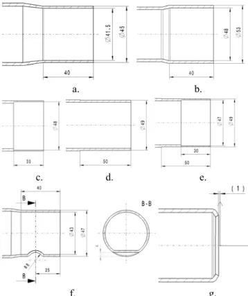
Fig. 5. Parameterized geometries in the guiding area a) one step bottleneck; b) two steps bottleneck;
c) enlargement; d) inner turning; e) flattening on the bottleneck; f) inner turning on bottleneck.
C. Bottom Cap Operations
From the “Bottom cap operations” set of parameters, there can be changed the geometry of the outer tube from the bottom cap area with the operations shown in fig. 6.
Fig. 6. CATIA software print screen showing the parameters from „bottom cap“ group
MASTER command represents a reset of the parameters. A draft representation of each operation is shown in fig. 7.
a. b.
c. d. e.
f. g. Fig. 7. Parameterized geometries in the bottom cap area are: a) bottleneck;
b) enlargement; c) inner turning; d) outer turning; e) inner and outer turning; f) transversal flattening on bottleneck; g) rolling.
D. Tube Operations
From the “Tube operations” set of parameters, there can be changed the geometry of the outer tube, from the area between guiding and bottom cap, with the operations shown in fig. 8.
Fig. 8. CATIA software screenshot showing the parameters between guiding and bottom cap
MASTER command represents a reset of the parameters. A draft representation of each operation is shown in fig. 9.
a. b.
c. d.
e. f.
Fig. 9. Parameterized geometries in the area between guiding and bottom cap are: a) round flattening;
b) flat flattening; c) transversal flattening; d) rolling; e) one ring turning; f) two rings turning.
E. Crimping
From „Crimping“ set of parameters, there can be changed the geometry of the outer tube with the operation of closing the shock absorber named Crimping, depending on previous set of operations, as shown in fig. 10.
Fig. 11. Parameterized dimensions of Crimping MASTER command represents a reset of the parameters. A crimping draft is shown in fig. 11, which is similar to any previous operation set before.
III. PROGRAMMING THE PARAMETERS
If, in the previous chapter of actual paper, there are described the necessary parameters of an outer tube pattern-model, next there is described an example of programming of one parameter, because this paper does not allow to describe all the above-mentioned 45 parameters needed to cover all range of operations used until today.
If the parameterized design supposes keeping dimensions as values of parameters,as in [3], for each operation manufactured on a tube, there has been created a specific parameter through which all geometries/operations are managed, without being a need to edit in part sketches or in part operations.
CATIA V5 software, through dedicated module CATIA Knowledge Advisor, helps the user in the designing activity with parameters, using specific tools such as: formulas, parameters, rules and reactions, which can be activated only after a specific condition is established beforehand, as in [1].
The formulas, in this case, allow us to create mathematical relations between dimensional parameters of the geometry, as in [4], and through these parameters, there is possible to change the tube geometry, operations and dimensional values which describe specific operations.
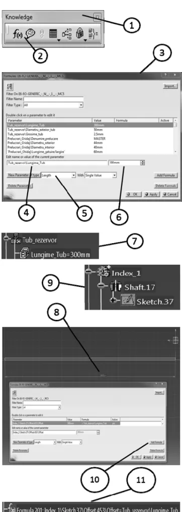
The below example describes how there can be created and programmed the “Tube Length” parameter so that, through this parameter, the length of the outer tube could be modified. This process is shown in fig. 12.
To create the “Tube Length” parameter, Formula (2) from Knowledge menu (1) has to be accessed. In Formula window (3) the name of the parameter should be added (4), the type of parameter should be selected (5) – in this case, the type of the parameter is length – and its value (6). After the parameter has been created (7) then it will be linked with the dimensional value (8) from the working sketch (9). The link between them is possible by accessing again Formula function (2) and selecting dimensional value (8), then choosing Add formula function (10) by choosing predefined parameter (7).
Thereby, by creating the parameter and creating the link between the parameter and dimensional value, there will be
IV. CONCLUSION
From the moment of implementation of the new working procedure by using CATIA V5 software and predefined working style, the time allocated for designing has been significantly reduced, and by doing a standardization of design activities, the quality of the work has considerably been improved.
Over the time, the new working style has known various development phases, namely: it started with the development of the new standardized model concept, then this model passed through a testing process and finally the improvement of the model continued until it was approved.
Future improvements will represent an update of the model in conformity with new technological needs.
In this paper, there have been described 24 operations which can be applied on the outer tube for. For the 24 operations there are needed 45 parameters and 700 formulas.
As a future research direction, by using the parameterized outer tube as a reference, we want to implement the parameterized design for the rest of shock absorber components, such as: rod, inner tube, setting, etc.
REFERENCES
[1] Drăghici, I. Suspensii şi amortizoare. Editura Tehnică, Bucureşti, 1970
[2] I. G. Ghionea, CATIA V5 – Culegere de aplicatii pentru activitati de laborator, Universitatea Politehnica din Bucuresti, v.1.0, 2013 [3] http://www.infoap.utcluj.ro/fabriasist/MasterRoboti/Curs3.pdf, page 3 [4]