ISSN 0104-6632 Printed in Brazil
www.abeq.org.br/bjche
Vol. 29, No. 02, pp. 275 - 283, April - June, 2012
Brazilian Journal
of Chemical
Engineering
TWO-PHASE EXPERIMENTAL HEAT TRANSFER
STUDIES ON A WATER-DIESEL SYSTEM IN A
SHELL AND TUBE HEAT EXCHANGER
V. Alagesan
1*and S. Sundaram
21School of Chemical and Biotechnology, SASTRA University, Phone: + 91 9894988976,
Fax: + 91 4362-264120, Thanjavur, Tamil nadu- 613402, India. E-mail: [email protected]
2
School of Electrical and Electronics Engineering, SASTRA University, Phone: + 91 9894084987, Fax: + 91 4362-264120, Thanjavur, Tamil nadu- 613402, India.
E-mail: [email protected]
(Submitted: April 26, 2011 ; Revised: November 19, 2011 ; Accepted: December 29, 2011)
Abstract - Two-phase heat transfer involving two immiscible systems is gaining importance in petrochemical
and allied industries. Varying compositions of diesel and water were experimentally studied in a 1:2 shell and tube heat exchanger. The data on pure water and diesel were fitted to an equation of the form.
m
1 Re
hϕ=a N .The two-phase multiplier, ΦL, was related to the Lockhart Martinelli (L-M) parameter, χtt2, using
the two-phase data and a correlation ΦL = b+c(χtt
2
)+d/(χtt
2
)2 was established. The two-phase heat transfer
coefficient was calculated based on the coefficients ‘a’ and ‘m’ for pure diesel and pure water along with ФL
and the L-M parameter. The calculated values of the two-phase heat transfer coefficient h2ϕ based on pure
diesel and pure water suggest that diesel is a better reference fluid since the average error is much smaller compared to pure water as reference.
Keywords:Heat transfer coefficient; Shell and tube heat exchanger; Two-phase flow; Lockhart Martinelli
parameter; Two-phase multiplier.
INTRODUCTION
In process industries, two-phase flow has gained importance over the years. A better understanding of the rates of momentum and heat transfer in multi-phase flow is a must for the optimum design of heat exchangers. Since experimentation in two-phase flow is cumbersome, heat transfer coefficient correlations are being developed using pure fluid thermo-physical properties, dimensionless numbers such as the Reynolds number and Nusselt number.
Considerable research is being pursued in
276 V. Alagesan and S. Sundaram
2005;), vertical and horizontal tube (Benbelk A. Shannak., 2008), across staggered rod bundles (Dowlati et al., 1992), helicoidal pipes (Awwad et al., 2000), etc. The heat transfer for gas-liquid flow in a plate type heat exchanger has also been investigated (Vlasogiannis et al., 2002). Ramachandran et al. (2006) conducted two-phase experiments in a compact heat exchanger and developed heat transfer correlations for two-phase heat transfer involving liquid-liquid systems. Ramachandran et al. (2008) developed a model for predicting the two-phase heat transfer coefficient of liquid-liquid systems using single phase data.
In this work, we propose a model formulation analogous to the L-M parameter model for heat transfer involving a liquid-liquid mixture. However, the study of heat transfer involving two immiscible liquids in a shell and tube heat exchanger has not been extensively studied. Experiments were carried out in a shell and tube heat exchanger with hot water as the heating fluid (service fluid) and two-phase mixtures of water-diesel in different ratios as the heated fluid (process fluid) on the shell side. The heat transfer coefficients on the shell side were correlated with Reynolds numbers and the relations between the Lockhart-Martinelli parameter, the quality and the two-phase multiplier were developed based on the experimental data. The work is confined to laminar flow in the present study.
EXPERIMENTAL SECTION
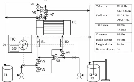
A schematic diagram of the 1-2 pass shell and tube heat exchanger experimental setup is shown in Figure 1, which gives in detail the size and specifications of all the units involved. Triangular pitch was used for the arrangement of tubes. Heating fluid and process fluid were pumped through the tube and shell side of the heat exchanger, respectively, using 0.25 HP pumps. Water was heated using a 2 kW heater and the temperature of the hot fluid was maintained constant at 70°C in the tank using suitable thermostats with an accuracy of ±0.5°C. Pumping continued through both the channels until a steady state was obtained with respect to the inlet and outlet temperatures of both the fluids. The flow rate was measured using Gallenkamp rotameters with an accuracy of ±0.1 LPM. The hot water flow rate was constantly maintained by rotameter R1 and circulated through the tube side, while the shell side test fluid mixture was metered through rotameter R2. The rotameters were calibrated before use. The flow rates of the two streams were adjusted using hand operated valves (2) and (4). The temperatures were recorded in the exit and inlet using RTD with an accuracy of ± 0.1°C. Six compositions (0% to 100% diesel) of the water-diesel system were used in the study. The two-phase system was kept in suspension using an agitator.
CALCULATION METHODOLOGY
Tube Side
On the tube side, the heating fluid (hot water) circulated at a constant rate. The tube side Reynolds number, Nusselt number, heat transfer coefficient and heat transfer rates were calculated using Equation (1) to (4).
i Re
vD
N = ρ
μ (1)
0.333
Re Pr Nu
i
N N
N 1.86
L D
⎧ ⎫
⎪ ⎪
= ⎨ ⎬
⎪ ⎪
⎩ ⎭
(2)
Nu 1t
i
N k
h
D
φ= ⎜⎛ ⎞⎟
⎝ ⎠ (3)
(
)
h ph h2 h1
Q=m C T −T (4)
The properties µ, ρ, k were calculated based on the average of the inlet and outlet temperatures.
Shell Side
Various compositions of diesel and water were circulated at different flow rates. The heat transfer coefficients for the single phases were related to the Reynolds number using Equation (5) and the constants a and m established by regression analysis.
m 1 Re
hφ=aN (5)
The quality (X) is defined by Equation (6),
(
)
(
wf wf)
1 X
V 1
V
=
⎡ + ρ ⎤
⎢ ρ ⎥
⎣ ⎦
(6)
The Reynolds number is calculated based on Equation (7) to (12):
(
)
m fX w 1 X
ρ = ρ + ρ − (7)
(
)
m fX w 1 X
μ = μ + μ − (8)
t o
S S S
P D
A D B
P
⎛ − ⎞
= ⎜ ⎟
⎝ ⎠ (9)
m m S
S V G
A
⎛ ρ ⎞
= ⎜ ⎟
⎝ ⎠ (10)
(
)
e 2 2
o t o 1.1 D
D P 0.91D
=
− (11)
S e Re
m G D
N = ⎜⎛ ⎞⎟
μ
⎝ ⎠ (12)
The correction factor (Ft) is a function of the shell
and tube fluid temperatures and was correlated as a function of two dimensionless temperature ratios (Sinnott, 2000):
(
)
(
c1h1 c2h2)
(
(
h2c1 h1h1)
)
T T T T
R , S
T T T T
− −
= =
− − (13)
R is equal to the shell side fluid flow rate times the fluid mean specific heat divided by the tube side fluid flow rate times the tube side fluid specific heat.
S is a measure of the temperature efficiency of the exchanger.
The true temperature difference is expressed as:
m t lm
T F T
Δ = Δ (14)
The overall heat transfer coefficient (U) and process side heat transfer coefficient (h2ϕ) are
determined using Equation (15) and (16):
h m Q U
A T
=
Δ (15)
2
o o
i o
w i 1t 1
h
D D ln
D
1 D
U 2 k D h
φ
φ
=
⎧ ⎛ ⎛ ⎞⎞ ⎫
⎪ ⎜ ⎜ ⎟⎟ ⎛ ⎞⎪
⎪⎛ ⎞−⎜ ⎝ ⎠⎟− ⎜ ⎟⎪
⎨⎜ ⎟⎝ ⎠ ⎜ ⎟ ⎜ ⎟⎬
⎪ ⎜ ⎟ ⎝ ⎠⎪
⎪ ⎝ ⎠ ⎪
⎩ ⎭
(16)
The single phase heat transfer coefficient was related to the Lockhart-Martinelli parameter (χtt2)
using the slope ‘m’ of Equation (5).
m 2 m
2 f w
tt
f f 1 X
X
− ⎛ ⎞⎛ ⎞
− ρ μ
⎛ ⎞
χ =⎜ ⎟ ⎜ ⎟⎜ ⎟
ρ μ
⎝ ⎠ ⎝ ⎠⎝ ⎠ (17)
The ratio of the two-phase heat transfer coefficient to the single phase heat transfer coefficient is
278 V. Alagesan and S. Sundaram 2 L 1 h h φ φ
Φ = (18)
Equation (19) relates the two-phase multiplier to the L-M parameter:
2 L tt 2
tt d
b c
Φ = + χ +
χ (19)
The error is defined by Equation (20) as,
2 2
2
h (exp) h (cal)
Error 100 h (exp) φ φ φ ⎡ − ⎤ = ⎢ ⎥ ⎢ ⎥
⎣ ⎦ (20)
RESULTS AND DISCUSSION
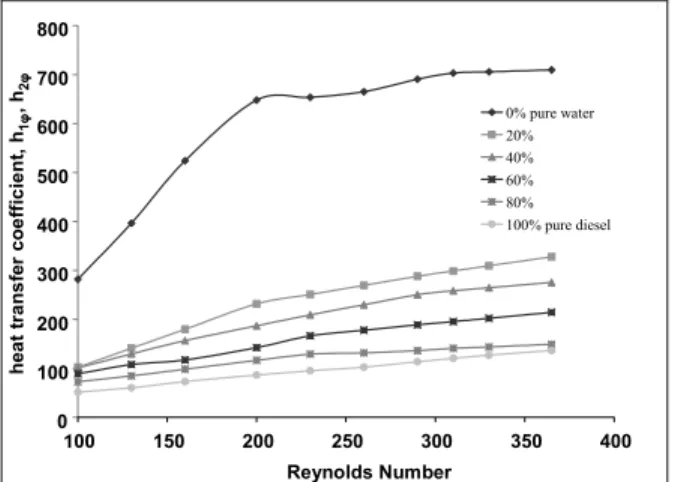
Figure 2 shows the variation of the single and the two-phase heat transfer coefficients with Reynolds number for the shell side process fluid. It is seen that the two-phase data fall within the boundaries of the pure water and pure diesel data. In addition, the increase in agitation enhances the uniformity of the two-phase mixture, thus preventing stratification of the phases. Hence, the overall physical properties of the mixture remain uniform throughout the flow channel. The uniformity of the two-phase mixture, coupled with increased convective currents driven by higher flow velocities, results in higher heat transfer coefficients. 0 100 200 300 400 500 600 700 800
100 150 200 250 300 350 400 Reynolds Number h eat t ran sf er co ef fi ci en t, h1 φ
, h2
φ 0% pure water
20% 40% 60% 80% 100% pure diesel
100 150 200 250 300 350 400
0 100 200 300 400 500 600 700 800 Reynolds Number h e a t tr an sf e r c o ef fi ci en t, h1 φ , h 2 φ 0 100 200 300 400 500 600 700 800
100 150 200 250 300 350 400 Reynolds Number h eat t ran sf er co ef fi ci en t, h1 φ
, h2
φ 0% pure water
20% 40% 60% 80% 100% pure diesel
100 150 200 250 300 350 400
0 100 200 300 400 500 600 700 800 0 100 200 300 400 500 600 700 800 Reynolds Number h e a t tr an sf e r c o ef fi ci en t, h1 φ , h 2 φ
Figure 2: Variation of the heat transfer coefficient with Reynolds number for different diesel -water compositions.
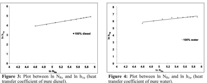
Figures 3 and 4 show the single phase heat
transfer coefficient (h1ϕ) and Reynolds number
relationship for pure diesel and pure water, respectively. The data for pure fluid (diesel or water) was fitted to Equation (5) by regression analysis and the resultant constants a and m for diesel and water are given in Table 1. Initially the L-M parameter correlation was used for predicting the pressure drop of gas-liquid two-phase systems and then the heat transfer coefficients for liquid-liquid two-phase flow were related to the L-M parameter (Ramachandran
et al., 2006, 2008) in Equation (17), where ‘m’
represents the power to which the Reynolds number is raised to determine the single phase heat transfer coefficient. The inlet and outlet temperatures of the shell side and tube side fluid are shown in Table 2 for different compositions. We maintained the inlet temperatures constant and measured the outlet temperatures once the heat exchanger attained the steady-state condition. The two-phase multiplier ΦL (Equation (18)) and the L-M parameter (Equation (17)) are shown in Figures 5 and 6 for 80% composition of the diesel–water system based on pure diesel and pure water, respectively, and are related by the heat capacity (Equation (19)). The variation of the two-phase multiplier (ΦL) with the L-M parameter (χtt2) shows an increasing concave
trend, while the h1ϕof pure diesel is less than the heat
transfer coefficient of the two-phase mixture. Because h1ϕbased on pure water is higher than h2ϕ,
the trend between ΦL and χtt2 is upwardly concave.
The constants b, c and d of the heat capacity correlation (Equation (19)) are given in Table 3 based on pure diesel and pure water as the reference fluid. The relationship of quality to the L-M parameter and the two-phase multiplier are shown in Figures 7 and 8. An increasing L-M parameter (χtt2)
0 1 2 3 4 5 6
4 4.2 4.4 4.6 4.8 5 5.2 5.4 5.6 5.8 6
ln NRe
ln
h 1
φ 100% diesel
4 4.2 4.4 4.6 4.8 5 5.2 5.4 5.6 5.8 6 ln NRe
0 1 2 3 4 5 6
ln
h1φ 100% diesel
0 1 2 3 4 5 6
4 4.2 4.4 4.6 4.8 5 5.2 5.4 5.6 5.8 6
ln NRe
ln
h 1
φ 100% diesel
4 4.2 4.4 4.6 4.8 5 5.2 5.4 5.6 5.8 6 ln NRe
4 4.2 4.4 4.6 4.8 5 5.2 5.4 5.6 5.8 6 4 4.2 4.4 4.6 4.8 5 5.2 5.4 5.6 5.8 6
ln NRe
0 1 2 3 4 5 6
0 1 2 3 4 5 6
ln
h1φ 100% diesel100% diesel
0 1 2 3 4 5 6 7 8
4 4.2 4.4 4.6 4.8 5 5.2 5.4 5.6 5.8 6
ln NRe
ln
h
1
φ
100% water
0 1 2 3 4 5 6 7 8
4 4.2 4.4 4.6 4.8 5 5.2 5.4 5.6 5.8 6 ln NRe
ln
h1φ
100% water
0 1 2 3 4 5 6 7 8
4 4.2 4.4 4.6 4.8 5 5.2 5.4 5.6 5.8 6
ln NRe
ln
h
1
φ
100% water
0 1 2 3 4 5 6 7 8
0 1 2 3 4 5 6 7 8
4 4.2 4.4 4.6 4.8 5 5.2 5.4 5.6 5.8 6 4 4.2 4.4 4.6 4.8 5 5.2 5.4 5.6 5.8 6
ln NRe
ln
h1φ
100% water 100% water
Figure 3: Plot between ln NRe and ln h1ϕ(heat
transfer coefficient of pure diesel).
Figure 4: Plot between ln NRe and ln h1ϕ(heat
transfer coefficient of pure water).
Table 1: Correlation constants a and m for the pure diesel and pure water systems.
Mass percentage of diesel a m
0 15.135 0.674
100 1.501 0.763
Table 2: Inlet and outlet temperatures for different compositions of cold side and hot side fluids
100% pure water 20% diesel-water
NRe of tube
side Tc1 Tc2 Th1 Th2
NRe of tube
side Tc1 Tc2 Th1 Th2
1106 304 321.6 343 331.8 1168 304 316.4 343 338.8
1104 304 314.0 343 330.2 1141 304 314.0 343 335.2
1101 304 310.8 343 329.5 1132 304 311.4 343 334.0
1099 304 309.1 343 329.1 1126 304 310.0 343 333.2
1097 304 308.1 343 328.8 1120 304 309.0 343 332.4
1095 304 307.3 343 328.5 1118 304 308.4 343 332.0
1094 304 306.8 343 328.3 1113 304 308.0 343 331.4
1092 304 306.3 343 328.2 1110 304 307.6 343 330.9
1091 304 306.0 343 328.1 1106 304 307.3 343 330.4
1090 304 305.7 343 327.9 1103 304 307.1 343 329.9
40% diesel- water 60% diesel-water
NRe of tube
side Tc1 Tc2 Th1 Th2
NRe of tube
side Tc1 Tc2 Th1 Th2
1172 304 316.4 343 339.4 1178 304 316.0 343 340.1
1152 304 313.2 343 336.8 1162 304 312.8 343 338.1
1142 304 311.3 343 335.4 1157 304 310.5 343 337.4
1135 304 310.1 343 334.4 1147 304 309.9 343 336.1
1131 304 309.0 343 333.9 1143 304 309.0 343 335.5
1128 304 308.4 343 333.5 1140 304 308.4 343 335.1
1125 304 308.0 343 333.0 1137 304 308.0 343 334.7
1122 304 307.6 343 332.6 1134 304 307.6 343 334.3
1119 304 307.3 343 332.2 1130 304 307.4 343 333.8
1118 304 307.0 343 332.1 1129 304 307.1 343 333.6
80% diesel- water 100% pure diesel
NRe of tube
side Tc1 Tc2 Th1 Th2
NRe of tube
side Tc1 Tc2 Th1 Th2
1183 304 315.5 343 340.8 1188 304 315.3 343 341.4
1171 304 312.3 343 339.3 1178 304 313.0 343 340.2
1165 304 310.6 343 338.5 1177 304 309.9 343 340.0
1159 304 309.7 343 337.7 1171 304 309.5 343 339.2
1154 304 309.0 343 337.0 1166 304 308.9 343 338.6
1153 304 308.3 343 336.9 1163 304 308.6 343 338.2
1151 304 307.9 343 336.6 1161 304 308.2 343 337.9
1149 304 307.5 343 336.4 1157 304 308.0 343 337.4
1147 304 307.2 343 336.1 1154 304 307.8 343 337.0
280 V. Alagesan and S. Sundaram L-M Parameter T w o P h as e M u lt ip li e r
0.075 0.080 0.085 0.090 0.095 0.100 1.05 1.15 1.25 1.35 1.45 L-M Parameter
0.075 0.080 0.085 0.090 0.095 0.100
T w o P ha s e M u lt ip li e r 1.05 1.15 1.25 1.35 1.45 L-M Parameter T w o P h as e M u lt ip li e r
0.075 0.080 0.085 0.090 0.095 0.100 1.05 1.15 1.25 1.35 1.45 L-M Parameter
0.075 0.080 0.085 0.090 0.095 0.100 0.075 0.080 0.085 0.090 0.095 0.100
T w o P ha s e M u lt ip li e r 1.05 1.15 1.25 1.35 1.45 1.05 1.15 1.25 1.35 1.45
Figure 5: Variation of the Two-Phase Multiplier (ΦL) with the L-M Parameter (χtt2) for the 80% diesel-water system based on pure diesel
r 0.95480925
L- M Parameter
T w o P h as e M u lt ip li e r
0.076 0.079 0.082 0.085 0.087 0.090 0.093 0.17 0.19 0.20 0.22 0.23 0.25 0.26
0.076 0.079 0.082 0.085 0.087 0.090 0.093 0.17 0.19 0.20 0.22 0.23 0.25 0.26 T w o P ha s e Mult ip li e r L-M Parameter
r 0.95480925
L- M Parameter
T w o P h as e M u lt ip li e r
0.076 0.079 0.082 0.085 0.087 0.090 0.093 0.17 0.19 0.20 0.22 0.23 0.25 0.26
0.076 0.079 0.082 0.085 0.087 0.090 0.093 0.076 0.079 0.082 0.085 0.087 0.090 0.093 0.17 0.19 0.20 0.22 0.23 0.25 0.26 0.17 0.19 0.20 0.22 0.23 0.25 0.26 T w o P ha s e Mult ip li e r L-M Parameter
Figure 6: Variation of the Two Phase Multiplier (ΦL) with the L-M Parameter (χtt2) for the 80% diesel -water system based on pure water
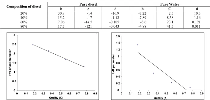
Table 3: The correlation constants b, c and d in Eq. (19) for varying diesel-water compositions
Pure diesel Pure Water
Composition of diesel
b c d b C d
20% 30.8 -14 -16.9 -7.22 2.5 10.3
40% 15.2 -17 -1.12 -7.89 8.38 1.16
60% 7.06 -14.5 -0.105 -8.6 23.1 0.191
80% 17.7 -121 -0.043 -4.88 41.5 0.011
0 0.5 1 1.5 2 2.5 3
0 0.1 0.2 0.3 0.4 0.5 0.6 0.7 0.8 0.9
Quality (X) T w o-phas e multiplier 0 0.5 1 1.5 2 2.5 3 Tw o-ph ase m u lt ip lier Quality (X)
0 0.1 0.2 0.3 0.4 0.5 0.6 0.7 0.8 0.9
0 0.5 1 1.5 2 2.5 3
0 0.1 0.2 0.3 0.4 0.5 0.6 0.7 0.8 0.9
Quality (X) T w o-phas e multiplier 0 0.5 1 1.5 2 2.5 3 0 0.5 1 1.5 2 2.5 3 Tw o-ph ase m u lt ip lier Quality (X)
0 0.1 0.2 0.3 0.4 0.5 0.6 0.7 0.8 0.9 Quality (X)
0 0.1 0.2 0.3 0.4 0.5 0.6 0.7 0.8 0.9 0 0.1 0.2 0.3 0.4 0.5 0.6 0.7 0.8 0.9
0 0.2 0.4 0.6 0.8 1 1.2 1.4 1.6
0 0.1 0.2 0.3 0.4 0.5 0.6 0.7 0.8 0.9
Quality (X) L -M p a ram a te r
0 0.1 0.2 0.3 0.4 0.5 0.6 0.7 0.8 0.9 Quality (X) 0 0.2 0.4 0.6 0.8 1 1.2 1.4 1.6 L-M p a ra m a te r 0 0.2 0.4 0.6 0.8 1 1.2 1.4 1.6
0 0.1 0.2 0.3 0.4 0.5 0.6 0.7 0.8 0.9
Quality (X) L -M p a ram a te r
0 0.1 0.2 0.3 0.4 0.5 0.6 0.7 0.8 0.9 Quality (X) 0 0.2 0.4 0.6 0.8 1 1.2 1.4 1.6 0 0.2 0.4 0.6 0.8 1 1.2 1.4 1.6 L-M p a ra m a te r
Figure 7: Plot between Quality(X) and Two-phase multiplier(ΦL) based on pure diesel for the water-diesel system
Figure 8: Plot between Quality(X) and the L-M Parameter(χtt2) based on pure diesel for the
Table 4: Comparison of experimental and calculated values of two-phase heat transfer coefficients for 20% and 40% diesel-water systems
20% diesel-water 40% diesel-water
NRe of shell
side h2ϕexp h2ϕcal based on
pure diesel
h2ϕcal based on
pure water
h2ϕexp h2ϕcal based on
pure diesel
h2ϕcal based on
pure water
100 102.22 102.08 110.60 100.71 101.49 104.09
130 141.02 145.55 141.04 129.36 131.71 120.75
160 179.82 190.37 192.60 156.61 162.06 160.96
200 231.55 226.61 253.23 186.82 191.49 207.89
230 250.91 247.33 270.28 209.12 208.93 222.54
260 269.49 264.30 285.43 229.71 223.74 235.19
290 288.09 290.62 304.16 250.31 246.57 250.91
310 298.97 305.47 318.12 258.40 259.90 262.83
330 309.45 320.06 325.81 264.61 273.00 269.56
365 327.79 341.85 332.10 275.47 291.59 277.10
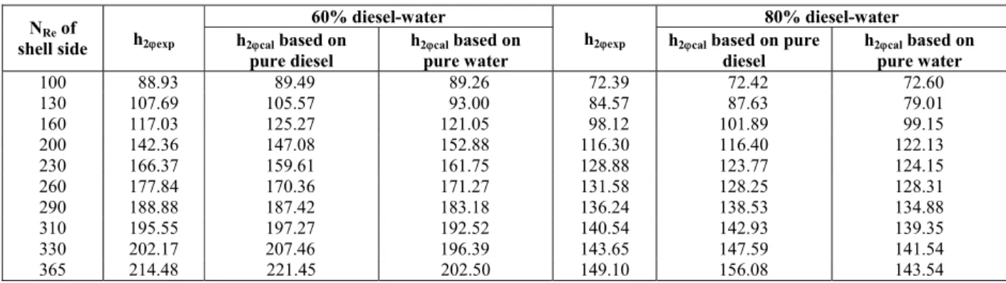
Table 5: Comparison of experimental and calculated values of two-phase heat transfer coefficients for 60% and 80% diesel-water systems.
60% diesel-water 80% diesel-water
NRe of
shell side h2ϕexp h2ϕcal based on
pure diesel
h2ϕcal based on
pure water
h2ϕexp h2ϕcal based on pure
diesel
h2ϕcal based on
pure water
100 88.93 89.49 89.26 72.39 72.42 72.60
130 107.69 105.57 93.00 84.57 87.63 79.01
160 117.03 125.27 121.05 98.12 101.89 99.15
200 142.36 147.08 152.88 116.30 116.40 122.13
230 166.37 159.61 161.75 128.88 123.77 124.15
260 177.84 170.36 171.27 131.58 128.25 128.31
290 188.88 187.42 183.18 136.24 138.53 134.88
310 195.55 197.27 192.52 140.54 142.93 139.35
330 202.17 207.46 196.39 143.65 147.59 141.54
365 214.48 221.45 202.50 149.10 156.08 143.54
Table 6: Average absolute deviation of h2ϕ based on pure water and pure diesel Average absolute deviation based on Composition of diesel
Pure diesel Pure water
20% 2.549 5.692 40% 2.237 3.730 60% 2.877 4.434 80% 2.470 2.633
CONCLUSION
Two-phase flow through a 1-2 pass shell and tube exchanger using a water-diesel system was studied. The correlations between X, ΦL and χtt² will be useful
for predicting two-phase heat transfer coefficients using pure phase thermo-physical properties. The correlation developed for the diesel-water system is useful for identifying heat transfer coefficients of two-phase systems for the range of Reynolds number studied. Based on the summary in Table 6, it can be concluded that, for this system, diesel is a better reference fluid compared to water since the average absolute deviation varies from 2.24 to 2.88 percent
studies on Palm oil-Water, Nitrobenzene-Water, Oleic acid-Water and Castor oil-Water are being carried out to verify whether Palm oil, Nitrobenzene, Oleic acid and Castor oil are also better reference fluids compared to water. The specific reason for diesel being a better reference fluid should be clarified by this comprehensive study of similar systems.
NOMENCLATURE
a, m constants for pure water and pure diesel in Equation (5)
Ah heat transfer area m²
282 V. Alagesan and S. Sundaram
b, c, d constants of the heat capacity correlation Equation (19)
Bs baffle spacing m
Cph specific heat of hot water J/kg K
Di inner diameter of the tube m
Do outer diameter of the tube m
Ds inner diameter of the shell m
De equivalent diameter
Ft temperature correction
factor
Gs mass velocity kg/m2 s
h1ϕ heat transfer coefficient of
pure diesel/purewater
W/m² K
h2ϕ two-phase heat transfer
coefficient
W/m² K
h1tϕ tube side (hot water) heat
transfer coefficient
W/m² K
k thermal conductivity of hot
water
W/m K
kw thermal conductivity of the
tube wall material
W/m K
L length of tube m
mh flow rate of hot water kg/s
NNu Nusselt number
NPr Prandtl number
NRe Reynolds number
Pt tube pitch (m)
R, S dimensionless temperature
ratios
Th1 inlet temperature of hot
water on the tube side
K
Th2 outlet temperature of hot
water on the tube side
K
Tc1 inlet temperature of cold
fluid on the shell side
K
Tc2 outlet temperature of cold
fluid on the shell side
K
vf volumetric flow rate of
diesel
m³/s
vm flow rate of a diesel-water
mixture
m³/s
vw volumetric flow rate of
water
m³/s
X quality parameter for the
two-phase system
Greek Letters
χtt2 Lockhart-Martinelli (L-M)
parameter
ΦL two phase multiplier
ΔTlm logarithmic mean
temperature
K
ΔTm true temperature difference K
velocity of hot water m/s
µ viscosity of hot water kg/m s
µw viscosity of water kg/m s
µf viscosity of diesel kg/m s
µm viscosity of diesel-water
mixture
kg/m s
ρ density of hot water
ρw density of water kg/m³
ρf density of diesel kg/m³
ρm density of diesel-water
mixture
kg/m³
REFERENCES
Awwad, A., Xin, R. C., Dong, Z. F., Ebadiam, M. A. and Soliman, H. M., Measurement and correlation of the pressure drop in air-water two-phase flow in horizontal helicoidal pipes. Int. J. Multiphase Flow, 21, 607-619 (2000).
Dowlati, R., Chan, A. M. C and Kawaji, M., Hydrodynamics of two-phase flow across horizontal in-line and staggered rod bundles. J. Fluid Eng., 114, 450-456 (1992).
Benbelk, A. Shannak, Frictional pressure drops of gas-liquid two-phase flow in pipes. Nuclear Eng. Design, 238, 3277-3284 (2008).
Lockhart, R. W. and Martinelli, R. C., Proposed correlation of data for isothermal two-phase two component flow in pipes. Chem. Eng. Prog., 43, 39-48 (1949).
Ramachandran, S., Kalaichelvi, P., Sundaram, S., Experimental heat transfer correlations for a liquid-liquid two-phase system in a compact heat exchanger. Indian J. Chem Tech., 1, 14-19 (2006).
Ramachandran, S., Kalaichelvi, P., Sundaram, S., Heat transfer studies in a spiral plate heat exchanger for water-palm oil two-phase system. Braz. J. Chem Eng., 25, 483-490 (2008).
Rani Hemamalini, R., Partheeban, P., Sarat Chandra Babu, C., Sundaram, S., The effect on pressure drop across horizontal pipe and control valve for air/palm oil two-phase flow. Int. J. Heat Mass Trans., 48, 2911-2921 (2005).
Sinnott, R. K., Chemical Engineering Design Volume 6. Butterworth-Heinemann Publishers, Third Edition (2000).
Spedding, P. L., Regime maps for air-water two-phase flow for both vertically downward and upward flow. Chem. Eng. Science, 46, 1773-1790 (1980).
calculating two-phase flow pressure drop and hold up. Int. J. Heat Mass Trans., 15, 1443-1449 (1972).
Vijayarangan, B. R., Jayanti, S., Balakrishnan, A. R., Pressure drop studies on two-phase flow in uniformly heated vertical tube at pressure up to the critical point. Int. J. Heat Mass Trans., 50, 1879-1891 (2007).
Vlasogiannis, P., Karagiannis, G., Argyropoulo, P., Bontozoglou, V., Air-water two-phase flow and heat transfer in a plate type exchanger. Int. J. Multiphase Flow, 28, 757-772 (2002).