ISSN 0104-6632 Printed in Brazil
www.abeq.org.br/bjche
Vol. 24, No. 02, pp. 223 - 232, April - June, 2007
Brazilian Journal
of Chemical
Engineering
HEAT TRANSFER IN POROUS MEDIA
N. Amanifard, M. Borji and A. K. Haghi
*
School of Engineering, University of Guilan P.O. Box 3756, Rasht, Iran. E-mail: [email protected]
(Received: August 5, 2006 ; Accepted: April 2, 2007)
Abstract - In this work, the effects of electrical double layer (EDL) near the solid/ liquid interface, on three dimensional heat transfer characteristic and pressure drop of water flow through a rectangular microchannel numerically are investigated. An additional body force originating from the existence of EDL is considered to modify the conventional Navier-stokes and energy equations. These modified equations are solved numerically for steady laminar flow on the basis of control volume approaches. Fluid velocity distribution and temperature with presence and absence of EDL effects are presented for various geometric cases and different boundary conditions. The results illustrate that, the liquid flow in rectangular microchannels is influenced significantly by the EDL, particularly in the high electric potentials, and hence deviates from flow characteristics described by classical fluid mechanics.
Keywords: Microchannel; Heat transfer; Pressure drop; EDL.
INTRODUCTION
The development of electronic industry and its trend toward miniaturization and high speed operating processes requires higher performance and small scale cooling systems. Removal of this amount
of heat, more than 106w/m2, attracts much attention
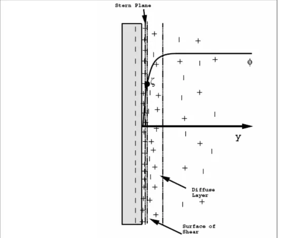
in resent researches. Many ideas for initiative cooling methods have been proposed including a microchannel heat sink. There is an electrical potential on the sides of microchannels because of substance of them. Furthermore, the fluid is ionized to prevent fouling in microchannels. The interaction between the microchannels electrical potential and the fluid’s ions is called the effect of Electric Double Layer. Because of the electrostatic interaction the focalization of the counterions near the solid surfaces is much more than the bulk liquid that is far from these solid surfaces. Hence, exists a very condensed layer of counterions are attracted to solid surfaces, and ions in this layer are immobile. This layer is named the compact layer. The thickness of this layer is about several Angstroms. Between the compact
layer and uniform bulk liquid, the compaction of ions gradually reduces to that of bulk liquid. Ions in this region, are influenced less by electrostatic interaction, and are movable. This region is called diffuse layer of the EDL. For macrochannel flow the EDL effects is safely negligible since the thickness of the EDL is very small compared with channel size. But in microchannel that can't be omitted.
diminished with the decrease in the size of the microchannel. Furthermore, the effects of aspect ratio and the hydraulic diameter on the flow and heat transfer in microchannel were investigated. These results provided noticeable experimental data and considerable manifestation that the flow and heat transfer in microchannels are strongly dependent upon the type and properties of the working fluid as well as geometric parameters of microchannels, and therefore may be different from what typically occur in the macrochannels (Wang and Peng, 1994). Wilding et.al. (1994) analyzed flow of water and various biological fluids in glass-capped silicon microchannels. The data illustrated an approximately 50% increase in the Darcy friction factor from the theoretical results. Similar results were observed by Jiang et.al. (1995) who studied flow of water through rectangular and trapezoid cross-section channels. The microchannels used in this study were formed by etching a silicon substrate and capping it with a glass wafer. Mala et.al. (1997) presented a paper on a microchannel flow and heat transfer between two parallel plates with electrokinetic effects. More recently, Mala et. al. (1997) reported experimental studies of flow of distilled water and aqueous solutions through silicon and glass microchannels between two parallel plates. Microchannels with a height ranging from 10-280µm were used in their measurements. Their results amply demonstrated that the liquid flow in such a microchannel was strongly influenced by the electrokinetic effects. For example, depending on the channel height and the electrical properties of the channel surface, the measured flow rate of the distilled water can be 80% lower than the predicted from the classical Poiseuille flow equation.
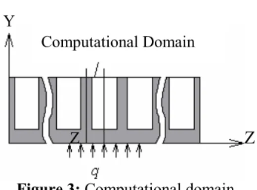
PHYSICAL MODEL AND COMPUTATIONAL DOMAIN
A schematic view, physical, and computational domain of such microchannels is depicted in Figure (1), Figure (2), and Figure (3), respectively. The microchannel has been studied is made of silicon. At the bottom, a uniform heat flux of q" arises from an electric chip that is connected to the microchannel. At the top of the channels, there is a Pyrex plate which makes an adiabatic condition. The width of microchannels and the wall thickness are represented
by Wc and Ws, respectively. The thickness of the
silicon substrate through which the heat flux is transformed to the cooling fluid flowing in channels
can be simply recognized as Ht-Hc, according to
Figure (1). The total length and width of
microchannels are Lt and Wt whose values of five
different cases are in Table (1). Moreover, steady incompressible and laminar fluid flow and steady heat transfer, with negligible radiative heat transfer and constant solid and fluid property have been assumed in computations. The cooling fluid flowing in channels is diluted electrolyte liquefied of Kcl that enters the channels with 20ºC temperature. By using of electrolyte liquid as cooling fluid, we can decrease the deposits. The silicon walls of microchannel will have static electric charge because of connecting to electric chip. A body force originates from the connection of this electric charge and the electrolyte liquid. A microchannel in the center parts of the plate will be considered in current work. As a result of the symmetry of the rectangular channel, we will center the computational domain in a half channel as shown in Figure (3).
Y
Z X
Mi crochannel Ws/2 Wc/2
Y
Z
Symmetry
Z Y
Z
Computational Domain
Figure 3: Computational domain
Table 1: Five different cases of microchannels
THE EDL EQUATION
Most of solid surfaces convey a static electric charge. In other words they will have superficial electric potential. If the liquid contains a very small number of ions (for instance, due to impurity), the electrostatic charges on the non-conducting solid surface will captivate the counterions, and repel similar ions in cooling fluid. Consequently, as we can see in Figure (4), the ions near the solid surface will found a new arrangement. The rearrangement of the charges on the solid surface and the balancing charges in the fluid is called the electric double layer. On the basis of electrostatic theorems, relation
between electric potential Ψ, and net volume charge
density ρe in each point of fluid, is decrypted by
Poisson equation as follows:
2 2
e
2 2
r. 0
y z
ρ
∂ ψ ∂ ψ+ = −
ε ε
∂ ∂ (1)
r, and 0
ε ε represent the dielectric constant of the
solution and permittivity of vacuum respectively. Assuming the Boltzman distribution equation is applicable, the number concentration of the type-i ion in an electrolyte fluid can be considered as follows:
i i i0
b
z e
n n .exp( )
k T − ψ
= (2)
Where ni0 and zi are the bulk concentration and the
valence of type-i ion, respectively, e is the elementary
charge, kb is the Boltzman constant, and T is the
absolute temperature. This equation is established only when the system is in equilibrium state. The net volume charge density is commensurate to difference between concentration of cations and anions, via
e 0
b
ze
z.e.(n n ) 2zen sinh( )
k T
+ − ψ
ρ = − = − (3)
Substitution of equation (3) into equation (1) leads to the conspicuous Poisson-Boltzman equation:
2 2
0
2 2
r 0 b
2zen ze
sinh( )
k T
y z
∂ ψ ∂ ψ+ = ψ
ε ε
∂ ∂ (4)
With considering the Debye-Huckel parameter and following dimensionless groups:
2 2 1
2z e n0
2
( )
k T r 0 b ℵ =
ε ε (5)
t c h t c 2H W D H W =
+ (6)
h
y Y
D
= (7)
Inlet Velocity )
m / s
h z Z
D
= (8)
h
K=ℵ.D (9)
ze
k T
b
ψ
=
ψ
(10)Where Dh is hydraulic diameter of the rectangular
channel, Y and Z are non-dimensional coordinates. By using above non-dimensionless groups equation (4) can be non-dimensionalized as:
2 2
2
2 2 K sinh
Y Z
ψ
ψ
ψ
∂ +∂ =
∂ ∂ (11)
Here K, is the non-dimensional electrokinetic diameter, depicted as the ratio of the hydraulic diameter to the electrical double layer thickness, and
ψ
is the non-dimensional electrical potentialstanding for the ratio of the electrical energy zeψ to
the thermal energyk Tb . Considering Figure (3) we
can issue following boundary conditions:
h h H
Y 0 Y
D W
Z 0 0 Z
Z D
ψ
ψ
ψ
ψ
= ⇒ = ζ = ⇒ ζ
∂
= ⇒ ∂ = = ⇒ ζ
=
=
(12)Where ζ defined by
b
ze k T
ζ
ζ = is a
non-dimensional zeta potential of the channel walls (here
ζ is the potential of the channel wall). The zeta
potential is an electric potential at the channel walls.
After solving equation (11) and computing
ψ
, thenet volume charge density can be obtained as follows:
e(Y, Z) 2zen sinh0
ψ
(Y, Z)ρ = − (13)
This net volume charge density is needed for computing of body forces originating from EDL.
Modified Navier-Stokes Equations
Assuming a laminar fully developed flow in rectangular channels in positive x-direction, the
components of velocity satisfy u=u(y, z) and
v= =w 0in terms of Cartesian coordinate. The
equation of motion is written as follows:
( )
2 2
x e
2 2
f f
u u 1 dP 1
E y, z
dx
y z
∂ +∂ = − ρ
µ µ
∂ ∂ (14)
In this equation the final term at right hand, is the effects of body forces originating from EDL. Considering following dimensionless groups we can obtain the non-dimensional form of equation (14),
f h 0
f
D U
Re =ρ
µ (15)
u u
U
= (16)
0 2 f P P P U − =
ρ (17)
h 0
x X
D Re
= (18)
h 0 2 f D Re dP dP dx
dX= ρ U (19)
x h 0
x
0
E D Re
E =
ζ (20)
0 0 1 2 f 2zn G U ζ =
ρ (21)
Substitution of resent equations in equation (14), the non-dimensional for of this equation can be obtained:
( )
2 2 x 1 2 2u u dP
G E sinh Y, Z
dX
Y Z
∂ +∂ = + Ψ
∂ ∂ (22)
Related boundary conditions are as follows:
c h c h H
Y 0 u 0 Y u 0
D W u
z 0 0 Z u 0
z D = ⇒ = = ⇒ = ∂ = ⇒ = = ⇒ = ∂ (23)
After numerical solution of equation (22) the velocity field will be obtained.
Energy Equation
As presented in Figure (1), a silicon wafer plate with a large number of microchannels is connected to the chip. A liquid is forced to flow through these microchannels to remove the heat. All microchannels are assumed to have a uniform rectangular cross-section with geometric parameters as shown in Table (1). For a steady-state, fully developed, laminar flow in a microchannel, the energy equation (with consideration of the axial thermal conduction in flow direction and the viscous dissipation) for the cooling liquid takes the specific form:
2 2 2
u f
2 2 2
x x y z
2 2
u u
f
C y z
f pf
∂θ= α ∂ θ ∂ θ ∂ θ+ + +
∂ ∂ ∂ ∂
µ ∂ ∂
+ +
ρ ∂ ∂
(24)
Where θ and αf are the temperature and the
thermal diffusivity of the cooling liquid,
respectively, Cpfis the specified heat capacity of the
cooling liquid. Based on presented computational domain, the adiabatic condition can be used along the channel symmetric center line:
z 0 0
z ∂θ
= ⇒ =
∂ (25)
At the bottom of channels, a uniform heat flux of q" is imposed over the heat sink, and can be expressed as:
f
y 0 q" k
y ∂θ
= ⇒ = −
∂
(26)
Hear kf is the thermal conductivity of the liquid
coolant. Since the thermal conductivity of the glass is about two-order of magnitude lower than that the top boundary is insulted. This is a conservative assumption which will lead to slight underestimation of the overall heat transfer coefficient. This assumption yields:
y H 0
y ∂θ
= ⇒ =
NUMERICAL SOLUTION METHOD
In current work finite volume method of Patankar is used to solve the continuity, momentum, and energy equations numerically. Since a detailed discussion of the FVM is available in Patankar (1980), only a very brief description of the main features of this method is given here.
In the FVM, the domain is divided into a number of control volumes such that there is one control volume surrounding each grid point. The grid point is located in the center of a control volume. The governing equation is integrated over each control volume to derive an algebraic equation containing the grid point values of the dependent variable. The discretization equation then expresses the conservation principle for a finite control volume just as the partial differential equation expresses it for an infinitesimal control volume. The resulting solution implied that the integral conservation of quantities such as mass, momentum, and energy is exactly satisfied for any control volume and of course, for the whole domain. The power-low scheme is used to model the combined convection-diffusion effects in the transport equations. The SIMPLER algebraic of Patankar is used to resolve the pressure-velocity coupling. The resulting algebraic equations are solved using a line-by-line Tri-Diagonal matrix Algorithm.
RESULTS AND DISCUSSIONS
The samples that have been considered in this article and their results are depicted in Table (2). Toh et. al. (2002) presents results without considering EDL for distances 1-4. They compared heir results with experimental results of Tuckermann (1984) . The thermal resistance was the basis of their comparisons, in the same way for verification of results in this study; the experimental results of Tuckermann are used. The thermal resistance is defined as follows:
out in
T T
R
q −
= (28)
In equation (28), Tout and Tin represent the
measured outlet and inlet temperature of cooling water, respectively, and q is the heat flux.
The numerically obtained results are compared with those of experimental results conducted by Toh et. al. (2002), and Tuckermann (1984) and presented in Table (2). It is shown that sufficiently reasonable agreement exists in such comparison. The thermal resistance due to decrease of volumetric flow rate
and consequently increase of Tout increases from
case 1 to case 4.
Table 2: Thermal resistance comparison
Figure 5: variation of dimensionless pressure drop with respect to dimensionless length of channel
Table 3: The percentage of variation of dimensionless distribution of pressure
The percentage of variation of dimensionless distribution affected by EDL Zeta Potential (200mv) Zeta Potential (75mv)
Case
7 / 24 4
/ 9 0
5 / 8 6
/ 2 1
2 / 10 1
/ 4 2
9 / 10 4
/ 4 3
7 / 13 2
/ 6 4
Figure 6: variation of dimensionless velocity profile with respect to dimensionless thickness of channel for case 0
104 × )
2
m K / W ( Thermal Resistance
Current numerical Result Toh’s Result
Tuckerman’s Result Heat Flux
2 (w / m )
×10-4 Case
301 / 0 253
/ 0 280
/ 0 6
/ 34 1
136 / 0 157
/ 0 110
/ 0 181
2
116 / 0 128
/ 0 113
/ 0 277
3
086 / 0 105
/ 0 090
/ 0 790
Figure 7: variation of dimensionless velocity profile with respect to dimensionless thickness of channel for case 4
Table 4: The percentage of variation of dimensionless velocity
Figure 8: variation of dimensionless Temperature profile with respect to dimensionless height of channel for case 3
The percentage of variation of dimensionless Velocity affected by EDL Zeta Potential (200mv) Zeta Potential (75mv)
Case
5 / 12 8
/ 4 0
1 / 2 9
/ 0 1
1 / 3 4
/ 1 2
5 / 3 6
/ 1 3
1 / 4 9
Figure 9: variation of dimensionless Temperature profile with respect to dimensionless height of channel for case 4
Table 5: The percentage of variation of dimensionless Temperature
CONCLUSION
The effects of the EDL at the solid/liquid interface on liquid flow and heat transfer characteristics through a rectangular microchannel numerically investigated. A two dimensional Poisson-Boltzman equation governing the electrical potential distribution in the cross section of rectangular microchannels has been solved based on the Debye-Huckel approximation. We can say that; considering the effects of EDL is very necessary for exact solution of equations of motion in electrolyte fluid flow. Because of using of ionized liquid in practical manners, the effects of EDL are not negligible. For the cases that characteristic length of microchannel is comparable with the thickness of EDL or exist a high electric potential, the liquid flow and heat transfer characteristics are significantly affected by the presence of the EDL, and omission of the effects of EDL causes to a much deviates from the prediction of conventional theorems. Presence of EDL causes to an apparent viscosity that is much more than the viscosity of fluid, and increasing of
zeta potential also causes to decreasing in volumetric flow rate. Similarly, presence of EDL leading to a large amount of pressure drop in microchannel heat sinks. As a result we can say that, existence of EDL causes to decreasing in efficiency of microchannel.
NOMENCLATURE
Cpf Specified heat capacity of
the cooling liquid
[j kg-1 k-1]
Dh Hydraulic diameter [m]
e Elementary charge [C]
Ex Streaming potential [v/m]
x
E Non-dimensional Streaming
potential
G Non-dimensional parameter
Ht Height of microchannel [m]
Hc Depth of microchannel [m]
k Non-dimensional
electrokinetic diameter
) -(
kb Boltzman constant [j mol-1 k-1]
kf Thermal conductivity of [w m-1 k-1]
The percentage of variation of dimensionless Temperature affected by EDL Zeta Potential (200mv) Zeta Potential (75mv)
Case
6 / 26 8
/ 8 0
8 / 9 9
/ 3 1
6 / 12 7
/ 4 2
1 / 13 1
/ 5 3
8 / 14 4
cooling liquid
Lt Total length of
microchannel
[m]
nio Bulk concentration of type-I
ion
[m-3]
P Non-dimensional pressure (-)
q” Heat flux [w m-2]
R Thermal resistance [m2 k w-1]
Re Reynolds number
T Absolute temperature [k]
Tout Measured outlet temperature [k]
Tin Measured inlet temperature [k]
u Velocity in X-direction [ms-1]
v Velocity in Y-direction [ms-1]
w Velocity in Z-direction] [ms-1
u Non-dimensional Velocity
in X-direction
) -(
Wc Width of microchannel [m]
Ws Wall thickness of
microchannel
[m]
Wt Total width of microchannel [m]
Y Non-dimensional coordinate (-)
Z Non-dimensional coordinate (-)
Zi Valence of type-i ion (-)
Greek Letters
f
α Thermal diffusivity of the
cooling liquid
[wkm2]
r
ε Dielectric constant of the
liquid
) -(
0
ε Permittivity of vacuum [CV-1m-1]
θ Temperature of cooling
liquid
[k]
ℵ Debye-Huckel parameter [m-1]
ζ Zeta potential [V]
ζ Non-Dimensional zeta
potential
) -(
f
ρ Density of cooling liquid [kg m-3]
e
ρ Net volume charge density [C m-3]
ψ Electric potential [V]
ψ
Non-Dimensional Electricpotential
) -(
REFERENCES
Jiang, X. N., Zhou, Z.Y., Yao, J., Y. Li, and Ye, X. Y., Micro-fluid Flow in Microchannel, In proc. Transdueers 95, Stockholm, Sweden, June 25-29, pp. 317-320, (1995).
Mala, G. M., Li, D., and Dale, J. D., Heat Transfer and Fluid Flow in Microchannel, International Journal of Heat and Mass transfer 40 pp. 3079-3088(1997).
Mala, G. M., Li, D., Werner, C., Jacobasch, H. J., Ning, Y. B., Flow Characteristics of Water through a Microchannel between TwoParallel Plates with Electrokinetic Effects, International Journal of Heat and Mass transfer 18, pp. 489-496(1997).
Patankar, S.V., Numerical Heat Transfer and Fluid Flow, Hemisphere, New York, 1980.
Peng, X.F., Peterson, G.P., and Wang, B.X., Heat Transfer Characteristics of Water Flowing through Microchannels, Experimental Heat transfer 7,pp 265-283 (1994).
Peng, X.F., and Peterson, G.P., Forced convection Heat Transfer of Single-Phase Binary Mixture through Microchannels. Experimental Thermal and fluid science 12 pp 98-104(1996).
Toh, K.C., Chen, X.Y., and Chai, J.C., Numerical Computation of Fluid Flow and Heat Transfer in Microchannels, International Journal of Heat and Mass Transfer 45, pp. 5133–5141(2002).
Tuckerman, D.B., Heat Transfer Microstructures for Integrated Circuits, Ph.D. thesis, Stanford University, (1984).
Tuckermann, D.B., and Pease, R.F.W., High-performance Heat Sinking for VLSI, IEEE Electron. Dev.Lett.EDL-2, pp. 126-129 (1981). Wang, B.X., and Peng, X.F., Experimental
Investigation on Liquid Forced Convection Heat Transfer through Microchannels, International Journal of Heat and Mass Transfer 37 (supple.1), pp 73-82(1994).