Gabriel Ciobanu (Ed.): Membrane Computing and Biologically Inspired Process Calculi 2009 EPTCS 11, 2009, pp. 51–69, doi:10.4204/EPTCS.11.4
© T. A. Basuki & A. Cerone & R. V. Carvalho This work is licensed under the
Creative Commons Attribution License. Thomas Anung Basuki
International Institute for Software Technology, United Nations University Macau SAR, China
Dipartimento di Informatica, Universit`a di Pisa Largo B. Pontecorvo 3, 56127 Pisa, Italy
[email protected] Antonio Cerone
International Institute for Software Technology, United Nations University Macau SAR, China
[email protected] Rafael V. Carvalho
International Institute for Software Technology, United Nations University Macau SAR, China
Understanding the behaviour of biological systems requires a complex setting of in vitro and in vivo experiments, which attracts high costs in terms of time and resources. The use of mathematical mod-els allows researchers to perform computerised simulations of biological systems, which are called in silico experiments, to attain important insights and predictions about the system behaviour with a considerably lower cost. Computer visualisation is an important part of this approach, since it pro-vides a realistic representation of the system behaviour. We define a formal methodology to model biological systems using different levels of representation: a purely formal representation, which we call molecular level, models the biochemical dynamics of the system; visualisation-oriented repre-sentations, which we call visual levels, provide views of the biological system at a higher level of organisation and are equipped with the necessary spatial information to generate the appropriate vi-sualisation. We choose Spatial CLS, a formal language belonging to the class of Calculi of Looping Sequences, as the formalism for modelling all representation levels. We illustrate our approach using the budding yeast cell cycle as a case study.
1
Introduction
The high complexity of biological systems has encouraged during the last decades extensive inter-disciplinary research comprising biology and other fields of science such as computer science, math-ematics, physics and chemistry. This interdisciplinary approach to biology resulted in a new field of study, called systems biology, which focuses on the systematic study of complex interactions in biologi-cal systems.
expected that the effort to understand biological mechanisms in terms of computer technology will pos-sibly lead to new techniques that are more robust, efficient and reliable to model and analyse complex systems.
Many mathematical formalisms have been proposed to model and analyse systems biology. Some of them are based on formalisms generally used for modelling concurrent systems, such as Petri Nets [31, 32, 19], theπ-Calculus [10, 30, 36, 37], and CCS (Calculus of Communicating Systems) [12]. Other formalisms are inspired by biological phenomena, such as compartmentalisation: Brane Calculi [7, 13], P Systems [28, 27], Calculi of Looping Sequences [2, 3], and Biocham [6, 8]. In particular, Calculi of Looping Sequences is a class of formalisms: Calculus of Looping Sequences (CLS) is the basic formalism [2] and has two important extensions, Stochastic CLS [2] in which reactions are associated with rates, and Spatial CLS [3], which includes spatial information.
These formalisms support the analysis of biological systems using tools based on numerical sim-ulation, stochastic simulation and model-checking techniques. Bianco and Castellini developed PSim, a simulator for Metabolic P Systems, a variant of P Systems [5]. Scatena developed a simulator for Stochastic CLS [33]. Biocham is equipped with a tool for the simulation and model-checking of bio-logical systems. The probabilistic model-checker PRISM has also been used to analyse some biobio-logical properties [21, 23, 22]. All these tools provide textual output as well as a plot of the simulation.
Texts and plots provide very detailed information on specific aspects of the analysed biological sys-tem. However, they are often inadequate when the aim is to acquire global knowledge about the high-level organisation and dynamics of the biological system. For example, in most experiments the analyst can only vary molecular concentrations in the environment and within cells, whereas the aim of an ex-periment or simulation may be to observe the resultant behaviour of cells or even the whole organ or organism. Such high-level behaviours can be better described through two or three dimensional visuali-sation/animation rather than using texts and plots.
One approach for modelling and visualising biological systems is based on the use of L-systems. L Systems use rewriting systems for modelling biological processes [16]. However, they are used mainly for visualising the development of plants [18, 29, 15]. Hammel and Prusinkiewicz model the behaviour of Anabaena at cellular level [18] by considering interactions between cells with external factors in the environment.
Michel, Spicher and Giavitto use rule-based programming language MGS to model and simulate the
λ phage genetic switch [25]. They present a multilevel model of the system; a molecular level defined using built-in Gillespie’s algorithm and a population of cells level defined using GBF (Group Based Field) and Delaunay topological collections.
David Harel and his group developed an approach in modelling at different levels of representa-tion [20]. They use object oriented approach and define the cell as the basic building block of their ap-proach. Their approach uses scenario to define system behaviour and uses animation on a 2-dimensional grid [1]. Scenarios define cell behaviour related with interactions between molecules in the environment and their receptors on cell membranes. Another interesting application of their approach is the mod-elling of pancreatic organogenesis [34]. In this application they show how molecular interactions affect cell growth and, in the end, affect the growth of mammalian pancreas. A three dimensional visualisation is used to visualise the pancreatic organogenesis process.
Another tool used to visualise biological systems according to a model of the system at the molecular level is Virtual Cell [35]. This tool is based on a deterministic numerical simulation of the model, which is defined using differential equations.
possible to track the causes of certain phenomena at cellular level down to specific biochemical reaction occurring at molecular level, we are still far from being able to entirely explain cell behaviour in terms of the biochemical reactions occurring within the cell and its environment. Moreover, based on natural ob-servation and experiments, it is also possible to give an accurate description of all phenomena observable at cellular level.
We define an approach to model biological systems at different levels of representation. We con-sider the molecular level, in which organic molecules interact through biochemical reactions, as the lowest level of our hierarchy. At this level, the representation is merely a mathematical formalisation of biochemical reactions, with no visualisation. The representation of higher levels of organisation and dynamics such as a cell, a tissue, an organ or an organism, is inspired by observations of the system behaviour under normal conditions. At these levels the mathematical formalisation mimics organisation and dynamics observed in nature and replicated in controlled experiments, with the aim to give a visu-alisation, possibly in three dimensions, of the modelled phenomena. We refer to these higher levels as visual levels, in contrast to the molecular level, for which we do not provide any visualisation. Each visual level has to be linked to the molecular level by a formal description of the way biochemical re-actions cause transitions of visual states. However such causal relations are not always fully understood in terms of biological theories. Therefore, transitions of visual states may sometimes be governed by rates observed in nature rather than by the underlying biochemistry modelled at molecular level or may be directly associated with the introduction or removal of biochemical signals, whose accumulation or degradation is not sufficiently explained in terms of biological theories.
This approach allows us to introduce changes to cells and their environment at the molecular level and observe the impact of such changes at the visual level. Changes at the molecular level may range from varying the concentration of a specific molecule or introducing a new kind of molecule with specific properties to the introduction of a plasmid within the cell or a virus in its environment.
The work of David Harel and his group [20, 1] and the work of Hammel and Prusinkiewicz [18] have similarity with our approach, in the sense that they also represent both molecular and cellular level. However their approaches consider molecules only as external factors that affect cells behaviour. The cellular level is modelled only in the environment and on the cell membrane, but not inside the cell. Moreover in David Harel’s approach, all rules are deterministic and randomness can only be introduced by defining random initial states of the system. In contrast, in our approach, we model and simulate stochastic behaviour by introducing reaction rates and controlling the occurrences of reactions using Gillespie’s algorithm.
Slepchenko, Schaff, Macara and Loew take an approach closer to ours by developing a tool to model biological systems at molecular level and visualise them at cellular level [35]. Their approach, how-ever, is based on differential equations, which are deterministically simulated using numerical simulation methods.
In this paper we use Spatial CLS to model both the molecular and visual level. We consider the cellular level as visual level and we use the cell cycle of budding yeast as a case study. However, spatial information is only introduced at the visual level, while the molecular level is modelled using a subset of Spatial CLS with no spatial information, which is equivalent to Stochastic CLS.
2
Using Spatial CLS for Visualisation
Calculi of Looping Sequences is a class of formalisms developed at the University of Pisa for the purpose of modelling biological systems [26, 2]. In this section we focus on one variant of the calculi called Spatial CLS [3], which supports the modelling of details about position and movement of the components in the system.
A Spatial CLS model contains a term and a set of rewrite rules. The term describes the initial state of the system, and the rewrite rules describe the events which may cause the system to evolve. We start by defining the syntax of terms. We assume a possibly infinite alphabetE of symbols ranged over by
a,b,c, . . .and a setM of names of movement functions. Each symbol represents an atomic component
of the system.
Definition 1 TermsT ,BranesB andSequencesS are given by the following grammar:
T ::= λ (S)d
Bd
L
⌋T T |T
B ::= λ (S)d B|B S ::= ε a
S·S
where a is a generic element ofE,εrepresents the empty sequence, and d∈D= ((Rn×M)∪{.})×R+. We denote withT,BandS the infinite set of terms, branes and sequences.
There are four operators in the formalism. A sequencing operator · is used to compose some components of the system in a structure that has the properties of a sequence. For instance, sequencing can be used to model DNA/RNA strands or proteins. The looping operator L
and containment operator ⌋ are always applied together, hence they can be considered as a single binary operator L
⌋ to be applied to one brane and one term. Looping and containment allow the modelling of membranes and their contents. Finally the parallel composition operator | is used to compose juxtaposition of entities in the system. Brackets can be used to indicate the order of application of the operators, and we assume
L
⌋ to have precedence over | .
In Spatial CLS there are two kinds of terms, positional and non-positional terms. Positional terms have spatial information, while non-positional terms do not. A term with a ‘.‘ in its spatial information represents a non-positional term.
Every positional term is assumed to occupy a space, modelled as a sphere. The spatial information of a term contains three parts: the position of the centre of the sphere, its radius and a movement function. In this way every object is assumed to have an autonomous movement. Variabled in the above syntax models such spatial information. In this paper we only consider terms without autonomous movement. Therefore, we can omit movement functions from our spatial information.
We now define patterns, which are terms enriched with variables. We assume a set of position variablesPV, a set of symbol variablesX and a set of sequence variablesSV. We denote byTthe set of all instantiation functionsτ:PV →D for the position variables.
Definition 2 Left Brane PatternsBPL,Sequence PatternsSP andRight Brane PatternsBPRare given by
the following grammar: BPL ::= (SP)u
BPL|BPL BPR ::= (SP)g
BPR|BPR SP ::= ε a
SP.SP x˜
x
Definition 3 Left PatternsPLandRight PatternsPRare given by the following grammar:
PL ::= (SP)u
BPLX L
u⌋PLX
PL|PL BPLX ::= BPL
BPL|X¯ X¯ PLX ::= PL
PL|X
PR ::= ε
(SP)g
BPRX L
g⌋PR
PR|PR
X
X¯
BPRX ::= BPR
BPR|X¯ X¯
where u ∈ PV , x ∈ X,x˜ ∈ SV and g∈T.
We denote the sets of all left patterns byPL, the set of all right patterns byPR. We denote by Var(P)
the set of all variables appearing in a patternP, including position variables fromPV.
Definition 4 Arewrite ruleis a 4-tuple ( fc,PL,PR,k), usually written as
[fc]PL k
7→PR
where fc:T→ {tt,f f}, k∈R+, Var(PR)⊆Var(PL), and each function g appearing in PR refers only to
position variables in Var(PL).
Rewrite rules are used to define reactions that may occur in a system. The left and right patterns of a rule is matched against the term that represents the current state of the system, to check its applicability. It is possible to define a rewrite rule that has a precondition defined by fc. A precondition is checked against any term matches in the left pattern of a rule. The rate constantk models the propensity of a reaction. The value 1/krepresents the expected duration of a reaction involving reactant combinations.
Barbuti, Maggiolo-Schettini, Milazzo and Pardini [3] define a semantics for Spatial CLS, as a Proba-bilistic Transition System. In this semantics, they consider each evolution step of a biological system as composed of two phases: (1) application of at most one reaction; (2) updating of positions according to the movement functions. In this paper we omit movement functions, simplifying the evolution step into one phase only.
The combination of looping and containment operators and parallel composition operators in Spatial CLS defines a notion of layers in the terms. The parallel composition operators model the objects as multisets, while the looping and containment operators create boundaries between these multisets. Ob-jects within the same boundary are considered to be in the same layer. We need to define some functions in order to calculate the rate of a rule application. In the following definitions, we denote the multiset of top-level elements appearing in a pattern P by ¯P, and assume the functionn:T ×T →Nsuch that
n(T1,T2)gives the number of timesT1appears at top-layer inT2. We defineτ as instantiation function for position variables andσ as instantiation function for other variables.
comb(PL1|PL2,τ,σ) = comb(PL1,τ,σ).comb(PL2,τ,σ)
comb( BPLX
L
u⌋PLX,τ,σ) = comb ′(BP
LX,τ,σ).comb′(PLX,τ,σ)
comb(SPu,τ,σ) = 1
comb(PL|U,τ,σ) = ∏T∈PL¯τσ
n((PL|U)τσ,T) n(PLτσ,T)
.comb(PL,τ,σ), U∈BV∪TV
comb′(PL,τ,σ) = comb(PL,τ,σ)
binom(T1,T2,T3) = ∏T∈T¯1∏ni=(T13,T)n(T n(T2,T)+i
2,T)−n(T1,T)+i
(R:[fc]PL k
7→PR)∈R fc(τ) =tt τ∈T σ∈∑
PLτσ
R,PLτσ,comb(PL,τ,σ)
−−−−−−−−−−−−→PRτσ
B−−−→R,T,c B′ R∈RB T1 R,T,c
−−−→T1′
BL
d ⌋T1 R, BL
d⌋T1,c
−−−−−−−→ B′L
d ⌋T1 B
L
d⌋T1 R, BL
d⌋T1,c
−−−−−−−→ B′L
d⌋T1
T1 R,T,c
−−−→T1′
T1|T2
R,T,c.binom(T,T1,T2)
−−−−−−−−−−−→T1′|T2
Figure 1: Inference rules used for calculating rates of rewrite rules
The following definition gives all the reactions enabled in a state, by also taking into account the subsequent rearrangement:
Appl(R,T) = (Tr,c,T′,T′′)|T −−−→R,T,c T′∧T′′=Arrange(T′)6=⊥
The numberm(TR)of different reactant combinations enabled in state T, for a reactionR, and the total numbermT of reactions considering a set of rulesR, are defined as:
m(TR)=
∑
(Tr,c,T′,T′′)∈Appl(R,T) c
and
mT=
∑
R∈Rm(TR)
Let T describe the state of the system at a certain step, and kR denote the rate associated with a rewrite ruleR. At each step of the evolution of the system, in order to assume that at most one reaction can occur, we have to choose a time intervalδtsuch that(∑R∈RkRm(R)
T )δt≤1. Given a set of rewrite rulesR, we choose an arbitrary valueNsuch that for each ruleR∈Rit holds 0<kR/N≤1. Then we compute the time interval for a step asδt=1/NmT, thus satisfying the above condition. The value ofN also determines the maximum permitted length of each step as 1/Ntime units.
The probability that no reaction happens in the time intervalδtis:
¯
pT=1−
∑
R∈R(
∑
(Tr,c,T′,T′′)∈Appl(R,T) kR
NmT
c)
and the probabilityP(T1→T2,t)of reaching stateT2fromT1within a time intervalδtaftertis such that:
P(T1→T2,t) =
∑
R∈R(
∑
(Tr,c,T′,T2)∈Appl(R,T1) kR
NmT1 c) +
¯
pT1 ifT1=T2
0 otherwise
Definition 5 Given a finite set of rewrite rules R, the semantics of Spatial CLS is the least relation satisfying the following inference rules:
(Tr,c,T′,T2)∈Appl(R,T1) R∈R
p=P(T1→T2,t) δt=Nm1T
1
hT1,ti p
→ hT2,t+δti
p=P(T →T′,t) δt=N max1(1,m
T1)
hT,ti→ hp T′,t+δti
Application of a reaction may still result in non well-formed terms (e.g. a term that contains collision of two objects). To solve this problem, we define the algorithm described in Section 4 to rearrange objects in the system. In this section we describe some assumptions about space and spatial information used in our approach.
First, we limit the direction where any object in the system can move. We assume that the space occupied by each object in the system is inRnand each object can only move along one axis at one time.
For every axis, there are two possible directions. So in total there are 2npossible directions. Therefore inR3any object can move along 6 possible directions.
Positional terms in Spatial CLS have size, which is defined as the radius of the sphere that encloses the term. It is possible to define reactions that modify this size. In our algorithm, we assume that the maximum sizes of all objects in the same layers are known. We assume the existence of an n -dimensional grid, which divides the space occupied by a biological system into cubes (we are working in n=3 dimensions) with fixed size defined in such a way that every object in the system fits inside it.
Initially objects of a biological system are positioned inside cubes. Reactions defined for a biological system can create new objects, move existing objects to different positions or remove objects from the system. New objects are also positioned inside cubes. Therefore, the only time we need rearrangement is when two objects are inside the same cube. In this case, we will need to run the rearrangement algorithm explained in Section 4.
3
Levels of Representation in Spatial CLS
In this section we define an approach to model biological systems at different levels of representation using Spatial CLS. We distinguish between a molecular level, in which rewrite rules are used to model biochemical reactions among molecules, and one or more visual levels, in which rewrite rules define the dynamics of a higher level of organisation of the biological system under analysis. These rewrite rules refer to a single level of representation. Therefore, we call themhorizontal rules.
In this paper we consider only the cellular level as a visual level. At visual level the state of the system, which is called visual state, is defined using the spatial information in positional terms of the system. A visual state describes three kinds of information:
1. spatial information;
2. a stage of the system evolution, which we call visual stage;
3. information on whether that stage has been visualised.
In this way, we can attain visualisation using spatial information. Moreover, visual states represent both the biological stage of the system and the status of the visualisation, while rewrite rules control the flow of the visualisation. Visualisation can then be used to simulate the behaviour of the system and to perform comparison with and prediction of in vivo and in vitro experiments.
At molecular level we can see biological systems as composed of molecules which are not associated with spatial information in our model. The state of the system is represented by the combination of molecular populations. State transitions are defined as rewrite rules representing biochemical reactions modifying molecular populations. Therefore the molecular level is modelled using a subset of Spatial CLS equivalent to Stochastic CLS.
To model a biological system, we can start from the visual level. The information about the system behaviour at this level is purely descriptive. It is based on observation of visible events independently of the biochemical processes that cause them. Such visual events are modelled through transitions of visual states, whose spatial information is defined in such a way to mimic visible events observed during in vivo and in vitro experiments. Molecules are confined within membranes using the looping and containment operator. However, such a confinement is logical rather than spatial. Chemical reactions are modelled by rules with no visual effect and then linked to the visual level by vertical rules, which control the transition of stage in the system evolution, by evaluating conditions at molecular level and checking that the current stage has been visualised.
4
Case Study: Cell Cycle
In this section we illustrate our approach using the cell cycle of budding yeast as a case study.
4.1 Visual Level
Cell cycle consists of four phases: G1 - S - G2 - M. However, at cellular level, only phase S fully characterises a visual stage, that is the stage where chromosomes inside the nucleus are replicated. Phase
G1incorporates different steps of cell growth, phaseG2does not have any visual counterpart and phase
Mincludes one visual stage corresponding to nucleus division.
In our model we consider only two steps in cell growth: the cell size before and after the growth. Therefore we define 4 visual stages:
1. small cell before growth (beginning of phaseG1);
2. big cell after growth (end of phaseG1);
3. chromosomes inside the nucleus (end of phaseS);
4. cell with two nuclei (phaseMbefore cytokinesis).
Based on the above explanation, we define three variables identifying visual stages:
• cell radius;
• number of nuclei in a cell;
• number of chromosomes in a cell nucleus.
Table 1 shows the values of these variables in each visual stage.
Stage cell radius # of nuclei # of chromosomes avg. time (min)
1 3r/4 single single 40
2 r single single 30
3 r single double 25
4 r double double 5
Table 1: The four visual stages of cell-cycle
the cell cycle. Barbuti, Maggiolo-Schettini, Milazzo and Pardini consider the 24 hour mammalian cell cycle [3]. In this paper, we model budding yeast cell cycle whose duration is only about 100 minutes [9]. The initial state of the system is defined by the following term:
(b)L
.,R⌋(m)L[0,0,f],3r 4
⌋((n)L⌋(cr.gN2.gB5|cr.gB2.gC20)|stage 1)
The above term represents a sphere with radiusR, which contains a cell positioned in its centre. The cell contains one nucleus, with 2 chromosomes inside. Each chromosome contains 2 genes, whose function will be explained in Section 4.2. The cell is initially in stage 1 (phaseG1). At this level the cell cycle is defined by the following rules:
R1: m
L
[p,f],34r ⌋(X | stage1)
0.025
7−→ mL[p,f],r⌋(X|stage1|visualised1)
R2: mL[p,f],r⌋((n)L
u⌋(cr.x˜|cr.y)˜ | stage2) 0.033 7−→(m)L
[p,f],r⌋((n)Lu⌋(2cr.x˜|2cr.y)˜ | stage2 |visualised2)
R3: n L
[(0,0,0),f],2r 5 ⌋(2
cr.x˜|2cr.y)˜ |stage3 0.04 7−→
(n)L
[(−r 2,0,0),f],25r
⌋(cr.x˜|cr.y)˜ | nL [(r
2,0,0),f],25r ⌋(cr.˜
x|cr.y)˜ |stage3|visualised3
R4: m
L
[p,f],r⌋( n
L
u⌋X| n
L
v ⌋Y| stage4) 0.2 7−→
mL [p,f],3r
4 ⌋(
nL
u⌋X|stage4 |visualised4)| m
L [getpos,f],3r
4 ⌋(
nL
u⌋Y | stage4 |visualised4)
In the above rules we only model objects without autonomous movement. Function f on their spatial information represents a function that maps from positionpto the same positionp. Every cell is assumed to double its volume during cell cycle. This is shown by ruleR1, which represents the growing process in phaseG1. By changing the cell radius from 3r4 tor, the volume is nearly doubled. RuleR2represents the chromosomes replication inside nucleus. It is represented by modifying symbol crthat precedes each chromosome to 2cr. RuleR3represents the nucleus division, where the only nucleus inside a cell is duplicated into two identical nuclei. To avoid collision between nuclei, pairs of nuclei are moved toward opposite directions. Finally ruleR4 represents the cytokinesis, which divides the cell and all its contents into two daughter cells with the same size and content. This is represented by (1) removing the mother cell whose radius is r and having two nuclei, (2) putting a daughter cell with radius 3r4 at mother cell’s position, (3) putting a daughter cell with radius 3r4 at a new position determined by
getpos(). Symbols stage1,stage2,stage3,stage4 are used to model the current visual stage of a cell. Symbols visualised1,visualised2,visualised3,visualised4 decompose each visual stage into two visual states, which model whether the current stage has been visualised or not. Therefore, at visual level, rewrite ruleRi models the transition between the two visual states that correspond to visual stagei, that is from the non-visualised to the visualised state of stagei.
choices about where to visualise the duplicated chromosomes are purely aesthetic and are left to the implementation of the visualisation.
The constant associated with each rule defines the rate with which that rule is applied. The rate for ruleRi is calculated as the inverse of the average duration for visual stagei. This ensures that the time needed for each stage to be visualised mimics the actual time observed in nature. The last column of Table 1 shows the average durations of the four stages.
4.2 Molecular Level and Vertical Rules
To model cell cycle at molecular level, we adopt the model of budding yeast cell cycle introduced by Chen et al. [9]. It is a very detailed model based on differential equations. There is also a variant of this model for the eukaryotic cell cycle [11]. Li et al. developed a simpler model of budding yeast cell cycle using boolean network [24].
Cell cycle is controlled by complexes of cyclin and cyclin-dependent kinases. There are 4 kinds of cyclins involved in cell cycle:
• Cln3, which starts phaseG1;
• Cln2, which induce theG1/Stransition;
• Clb5, which controls the phaseS;
• Clb2, which controls the phaseM.
These four cyclins form complexes withCdc28.
We define rules that control the state of the system at molecular level. To define a link between the visual state (which is controlled by the horizontal rules at visual level) and the biochemical state at molecular level, we define 4 vertical rules that cause a transition to next visual stage when a specific condition at molecular level is verified. Since these rules do not correspond to any time-consuming biochemical process but operate at a meta-level by providing a link between distinct representation levels, we define them as instantaneous by using∞as the value for their rates.
Let condi be the condition at molecular level that triggers a transition from visual stage i to next visual stage. We define vertical rule
Ti:visualisedi|condi|stagei
∞
7−→condi|stagenext(i)
where
next(i) =
1 ifi=4
i+1 if 0<i<4
Symbolvisualisediis introduced by the application of ruleRi, which marks the completion of the visu-alisation of stagei. The completion of the visualisation of the current stage is obviously a precondition for the transition to next visual stage. Therefore, symbolvisualisediappears as a precondition in vertical rule Ti, which defines the transition to next visual stagenext(i). The removal ofvisualisedi by ruleTi enables ruleRnext(i)to be applied.
Vertical rules also allow the introduction and removal of biochemical signals whose accumulation or degradation is not sufficiently understood in order to be dealt with at molecular level. The form of vertical rules that deal with introduction and removal of biochemical signals is as follows:
•introduction,Ti:visualisedi|condi|stagei
∞
•removal,Ti:signal|visualisedi|condi|stagei
∞
7−→condi|stagenext(i)
We use the following convention for naming objects. Molecule names start with capital letters, except in some cases where the molecules could be in two different statuses. For example, we pre-fix the molecule names with i to indicate that this molecule is in inactive status. We also prefix the molecule names with pwhen the molecule is in phosphorylated status. Names starting withgare used for genes. We use ’-’ to concatenate two names of molecules, indicating a complex formed by binding two molecules.
Cell cycle starts when a cell grows in phaseG1. This is triggered by a growth factor, which is present in the environment, and binds with its receptor in the cell membrane. The resultant complex then triggers the production of cyclinCln3. CyclinCln3(after binding with its kinase partnerCdc28) activatesSBF
andMBF, the transcription factors for cyclinsCln2andClb5. GenesgN2 andgB5 control expression of cyclinCln2andClb5. CyclinCln2controls the transition between phaseG1andS. CyclinClb5controls phaseS. At this point some molecules that are not needed in this phase, but will be needed in later phases, are temporarily deactivated. In phaseG1,Clb5is deactivated bySic1. LaterCln2forms a complex with
Cdc28and phosphorylatesSic1, releasingClb5.Clb2, which is a cyclin needed in mitosis, is bound with
Sic1in phaseG1.Cdc14, which is needed in mitosis exit, is bound withNet1in phaseG1.Cdc14, which is abundant in this phase also activates phosphorylatedSic1, theClb5inhibitor.
Based on their duration, we classify reactions into four categories: very fast, fast, slow and very slow. We define four numerical values to characterise reaction rates for the categories above: 20, 5, 1, 0.25. The higher the rate, the faster the reaction. Obviously, reaction times are many magnitudes smaller than durations of visual stages defined in Table 1. Therefore, we introduce a speeding factors, which defines the ratio between these magnitudes for the specific visual representation we are modelling. The actual rate of a reaction is then given by the product between the speeding factor and the numerical value corresponding to the category of that reaction.
To simplify the model, we don’t define rules for complexation of cyclins with its kinase partners (Cdc28). PhaseG1is therefore modelled as follows:
S1: GF|(GFR|Y)L⌋X 20·s
7−→(iGFR|Y)L⌋X|Cln3 S2: Cln3|iSBF|iMBF 7−→1·s Cln3|SBF|MBF
S3: SBF|(n)L⌋(y˜.gN2.x|Y˜ )07−→.25·sSBF|(n)L⌋(y˜.gN2.x˜|Y)|Cln2
S4: MBF|(n)L⌋(y˜.gB5.x˜|Y)07−→.25·sMBF|(n)L⌋(y˜.gB5.x|Y˜ )|Clb5
S5: Sic1|Clb5 5·s
7−→Sic1−Clb5
S6: Net1|Cdc14 5·s
7−→Net1−Cdc14
S7: pSic1|Cdc14 20·s
7−→Sic1|Cdc14
S8: Sic1|Clb2 5·s
7−→Sic1−Clb2
S9: Cln2|Sic1−Clb5 5·s
7−→pSic1|Clb5|Cln2
The accumulation ofCln2triggers the transition from phaseG1toS[9]. We introduce the following vertical rule:
T1:visualised1|Cln2mc(Cln2,2)|stage1
∞
7−→Cln2n|stage2
to instantaneously perform the transition from stage 1 to stage 2, after ruleR1 has visualised the cell growth. The functionmc(r,i) represents the minimum concentration of r that is needed to trigger the transition to stagei.
Clb5-Cdc28) activateMcm1, which is the transcription factor forClb2. Expression of Clb2 is controlled by genegB2. CyclinClb2controls phaseM. ActiveCdh1, whose function is to degradeClb2, is deac-tivated by cyclin-dependent kinases. In this way the degradation ofClb2is postponed until the end of phaseM. FinallyClb2is transcribed and then binds withCdc28.
PhaseSis therefore modelled as follows: S10: pSic1|SCF
1·s 7−→SCF S11: Cln2|SCF
1·s 7−→SCF
S12: Cln2|Cdh17−→20·s Cln2|iCdh1
S13: Clb5|Cdh1 20·s
7−→iCdh1|Clb5
S14: Clb5|iMcm1 0.25·s
7−→Mcm1|Clb5
S15: Mcm1|(n)L⌋(y˜.gB2.x˜|Y) 1·s
7−→iMcm1|(n)L⌋(y˜.gB2.x˜|Y)|Clb2
The accumulation ofClb5 is the event that triggers the transition from phase S to phaseG2. We introduce the following vertical rule:
T2:visualised2|Clb5mc(Clb5,3)|stage2
∞
7−→Clb5mc(Clb5,3)|stage3|SPN
to instantaneously perform the transition from stage 2 to stage 3, after ruleR2has visualised chromosome duplication. Besides changing visual stage, the above rule also sends a signal (SPN) to start metaphase spindle. This signal is needed to activate Cdc15 in mitosis. Since it is unknown how to relate the accumulation of this signal with biochemical reactions at molecular level, we assume that this signal is available since the beginning of phaseG2.
The cyclin-dependent kinase (CDK) Clb2-Cdc28is the main controller of phase G2 andM. This CDK activatesMcm1, allowingClb2to accumulate. It also degradesMBFandSBF, stopping the tran-scription of Cln2and Clb5. Cyclin Cln2is then degraded by SCF, while the degradation of Clb5is regulated by Cdc20 and APC (Anaphase Promoting Complex). Mcm1 stimulates gene gC20 to pro-duceCdc20andAPCmust be phosphorylated by Clb2-Cdc28before it can bind withCdc20. During metaphase, theSPN signal activatesCdc15. ProteinCdc15then phosphorylatesNet1, releasingCdc14. ProteinCdc14is needed later in mitosis exit and also activatesCdh1. Tumor suppressorCdh1is needed forClb2degradation.
S16: Clb2|iMcm1 20·s
7−→Mcm1|Clb2
S17: Clb2|MBF 1·s
7−→Clb2|iMBF S18: Clb2|SBF
1·s
7−→Clb2|iSBF
S19: Mcm1|(n)L⌋(y˜.gC20.x|˜ Y)7−→20·s iMcm1|(n)L⌋(y˜.gC20.x|Y˜ )|Cdc20
S20: Clb2|APC 20·s
7−→APC−P|Clb2
S21: APC−P|Cdc20 1·s
7−→APC−Cdc20
S22: SPN|iCdc15 0.25·s
7−→SPN|Cdc15
S23: Cdc15|Net1−Cdc14 0.25·s
7−→Net1|Cdc14
S24: APC−Cdc20|Clb57−→1·s APC
S25: iCdh1|Cdc14 0.25·s
7−→Cdh1|Cdc14
The accumulation ofAPC−Cdc20 is the event that triggers the beginning of cytokinesis. We intro-duce the following vertical rule:
T3:SPN|visualised3|APC−Cdc20mc(APC−Cdc20,4)|stage3
∞
7−→APC−Cdc20mc(APC−Cdc20,4)|stage4
The main activity in the stage 4 is the degradation ofClb2byAPC(with the help ofCdc20orCdh1). ProteinCdc14is also active in this stage, producingSic1, which is needed to return to phaseG1.
S26: Cdc147−→5·s Sic1|Cdc14
S27: APC−Cdc20|Clb2 1·s 7−→APC S28: APC|Cdh1|Clb2
0.25·s
7−→APC|Cdh1
Finally, transition from cytokinesis to phaseG1 is triggered by the accumulation ofSic1. We intro-duce the following vertical rule:
T3:visualised4|Sic1mc(Sic1,1)|stage4
∞
7−→Sic1mc(Sic1,1)|stage1
to instantaneously perform the transition from stage 4 back to stage 1, after ruleR4has visualised cell division.
4.3 Algorithms for Simulation and Visualisation
The model of cell cycle defined using the formal approach introduced in Section 4.1 and Section 4.2 is used as the input for a variant of Gillespie’s simulation algorithm which extends the variant introduced by Basuki, Cerone and Milazzo [4]. The extension consists of the selection of the cell in which the current reaction has to occur and the control of the visualisation.
Step 0 InputMreactionsR1, . . . ,RM, andN valuesX1, . . . ,XN representing the initial numbers of each ofN kindsB1, . . . ,BN of molecules. Initialise time variabletto 0. Calculate propensities aj, for
j=1, ...,M. Calculate∑Mj=1aj.
Step 1 Ifvisualisedl is present in the term then visualise stageland execute vertical ruleTl.
Step 2 If the space is fully occupied then stop simulation. Otherwise generater1and calculateτ. Incre-menttbyτ.
Step 3 Generater2and calculate(µ,σ).
Step 4 ExecuteRµ inside cellσ. UpdateX1, . . . ,XN anda1, . . . ,aMaccording to the execution ofRµ.
Step 5 Calculate∑Mj=1aj. Return toStep 1.
Gillespie defines that the probability of reactionRj to occur is proportional toaj, thepropensity of reactionRj. The propensity of reaction Rj is the product of its rate cj and the number hj of distinct combinations of reacting molecules.
Since reactions are confined within cells, we need to extend Gillespie’s algorithm to choose in which cell the chosen reactionRµshould occur. LetCbe the number of cells andXkibe the number of molecules
of kindBkin thei-th cell. We defineXk=∑Ci=1Xki.
Let aij be the propensity of reaction Rj occurring inside the i-th cell. Then aij is defined as the product ofcj by the numberhij of distinct combinations of reacting molecules ofRj within thei-th cell. We defineaj=∑Ci=1aij. Iftis the current simulation time, thent+τ represents the time at which next reaction occurs, withτ exponentially distributed with parametera0=∑Mj=1aj. Time incrementτ, the indexµ of the reaction that occurs at timet+τand the indexσ of the cell in which such reaction occurs are calculated as follows.
τ= 1 a0
ln(1 r1
) (1)
(µ,σ) =the integers for which
µ
∑
j=1σ−1
∑
i=1aij< r2a0≤
µ
∑
j=1σ
∑
i=1wherer1andr2are two random real numbers which are uniformly distributed over interval [0,1]. We assume the existence of a function, calledgetpos(), that is responsible to find the correct position for a newborn cell and to resolve the spatial conflict that arises between cells. Naturally, the newborn cell should be attached to its parent cell. If we model the system inn-dimensional space, there are 2n
positions for this newborn cell. Functiongetpos()will find an empty position among these 2npositions. If it cannot find an empty position, it will choose one position and then push forward the other cells on that direction by one position. Since the space is limited by a sphere if the last cell is adjacent to the sphere boundary, it cannot be pushed forward. In this casegetpos()will search for any empty position for this cell. If no more empty position can be found, then the simulation must stop.
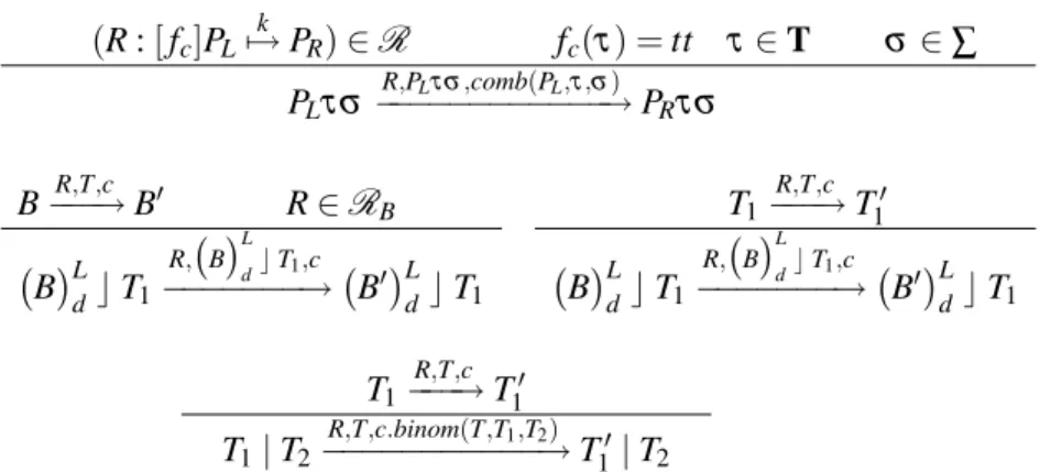
Figure 2 shows an example in 2-dimensional space. In the left picture, cell number 1 is about to divide, but all neighboring positions are occupied by other cells. Then in the right picture getpos()
chooses the position of cell number 2 as its target and divides cell number 1 into two newborn cells (grey colour). It pushes cell number 2 toward cell number 3, but cannot push cell number 3 forward because of the boundary. Then cell number 3 is moved to an adjacent empty position, along a different direction.
Figure 2: Application ofgetpos()
After executing reactionRµ (step 4 of the algorithm), we need to update the molecular populations
and propensity functions that are affected by application ofRµ. Gibson and Bruck [17] define a data
structure to support an extension of Gillespie’s First Reaction Method. We use their notion of dependency graph in order to simplify the process of updating molecular populations and propensity functions. In this way we need to update them only if they are affected by the application of reactionRµ.
4.4 Visualisation of Cell Cycle
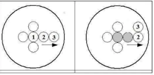
Figure 3 shows the visualisation of cell cycle in our tool. The picture on the top left shows the initial stage of the system, in which the sphere that limits the proliferation space only contains one small cell. This cell grows (top centre) and duplicates its chromosomes (top right). Nucleus division (bottom left) and cell division (bottom centre) complete the cell cycle. All newly born cells concurrently repeat the cell cycle and finally the simulation stops because the space is full of cells (bottom right).
Figure 3: Visualisation of cell cycle by our tool
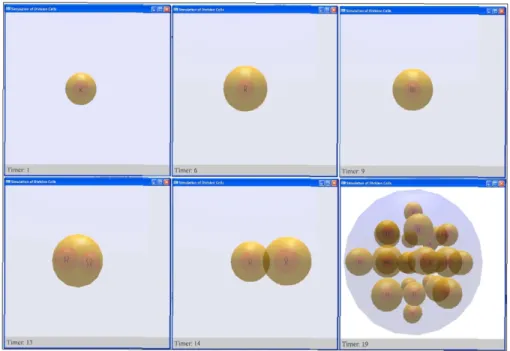
• healthy cell, if no virus is inside the cell;
• lightly infected cell, if the number of viruses inside it is less thanvirusT H;
• severely infected cell, if the number of viruses inside it is greater than or equal tovirusT H.
To represent the infection level of a cell, we use colours in our visualisation. We colour healthy cells with orange, lightly infected cells with green and severely infected cells with blue. Figure 4 shows the visualisation of virus attack in our tool. The tool also supports the generation of a report file, describing the details of reactions occurring in the system. By combining our observation from the visualisation and the report, we can find interesting things about the model. For instance, in the visualisation we may observe that a severely infected cell can no longer proliferate, while other infected cells can still proliferate. We can later analyse the report generated by the tool and find out that the observed situation is related to the stage of the cell at the moment when it is infected by virus. If the cell is infected while it is still growing, this may cause the cell to loose its growing capability, which means that the cell can no longer proliferate. In contrast if the cell is infected after the growing phase is already over, it can still proliferate.
5
Conclusions and Future Work
Figure 4: Visualisation of virus attack
biological system under analysis. We have chosen Spatial CLS to model all representation levels in or-der to formally describe, for every visual level, the spatial information needed to quantitatively define all visual details that are believed to be essential for an effective visualisation at that level. Visual details whose quantitative definition is a purely aesthetic matter are not included in the formal model and their quantitative definition is left to the implementation. Each molecular or visual level is defined by an initial term and a set of rewrite rules, which we called horizontal rules since they only refer to that level. Each visual level is linked to the molecular level by a meta-level of vertical rules, which also cater to lack of sufficient knowledge at molecular level.
We have then presented the budding yeast cell cycle as the case study to illustrate our approach, choosing the cellular level as the single visual level. Those visual details for which a quantitative charac-terisation is essential for visualisation, such as the position and size of cells, have been formally modelled, whereas irrelevant quantitative details, such as the position within the nucleus of duplicated chromo-somes, are not.
to the normal cell cycle, the tool supports the injection of a virus in the environment where the cells proliferate. The virus can enter a cell through its membrane, duplicate itself inside the cell, and cause the degradation of the growth factor receptor. The visualisation shows that some small infected cells can no longer proliferate while big infected cells can still proliferate. Although this specific situation is an obvious consequence of the degradation effect the virus has on the growth factor receptor of the cell, it actually illustrates that, in general, the visualisation of higher levels of organisation has the potential to highlight important behaviours that would not be captured through a formal analysis conducted at the molecular level.
As future work, we plan to extend the work by Basuki, Cerone and Milazzo [4], by implementing Spatial CLS within the MAUDE tool and parsing the output generated by MAUDE to provide the ap-propriate input to our tool. In this way, simulations performed using MAUDE could be visualised using the tool. Moreover, counterexamples generated by the model-checker associated with MAUDE could be also visualised. Finally we plan several extensions to the tool implementation, such as
• the definition of several visual levels, corresponding to different magnifications of the biological system, with zooming capabilities to move from consecutive visual levels;
• the capabilities to save simulations and to re-visualise them at a later stage;
• the structuring and visualisation of the textual information, currently provided as a single report file, by attaching it to the visual objects for which it is relevant.
References
[1] Hila Amir-Kroll, Avital Sadot, Irun R. Cohen, and David Harel. GemCell: A Generic Platform for Modelling Multi-Cellular Biological Systems.Theoretical Computer Science, 391:276 – 290, 2008.
[2] Roberto Barbuti, Giulio Caravagna, Andrea Maggiolo-Schettini, Paolo Milazzo, and Giovanni Pardini. The Calculus of Looping Sequences. In M. Bernardo, P. Degano, and G. Zavattaro, editors,Formal Methods for Computational Systems Biology, volume 5016 ofLNCS, pages 387–423. Springer, 2008.
[3] Roberto Barbuti, Andrea Maggiolo-Schettini, Paolo Milazzo, and Giovanni Pardini. Spatial Calculus of Looping Sequences.Electronic Notes on Theoretical Computer Science, 229(1):21–39, 2008.
[4] Thomas Anung Basuki, Antonio Cerone, and Paolo Milazzo. Translating Stochastic CLS into Maude. Elec-tronic Notes on Theoretical Computer Science, 227:37–58, 2009.
[5] Luca Bianco and Alberto Castellini. Psim: A Computational Platform for Metabolic P Systems. InMembrane Computing, volume 4860 ofLNCS, pages 1–20. Springer, 2007.
[6] Laurence Calzone, Franc¸ois Fages, and Sylvain Soliman. BIOCHAM: An Environment for Modeling Bio-logical Systems and Formalizing Experimental Knowledge. Bioinformatics, 22(14):1805–1807, July 2006. [7] Luca Cardelli. Brane Calculi - Interactions of Biological Membranes. In V. Danos and V. Schachter, editors,
Computational Methods in Systems Biology, volume 3082 ofLNCS, pages 257–280. Springer, 2005. [8] Nathalie Chabrier-Rivier, Franc¸ois Fages, and Sylvain Soliman. VICE: A VIrtual CEll. In V. Danos and
V. Schachter, editors,Computational Methods in Systems Biology, volume 3082 ofLNCS, pages 172–191. Springer, 2005.
[9] Katherine C. Chen, Laurence Calzone, Attila Csikasz-Nagy, Frederick R. Cross, Bela Novak, and John J. Tyson. Integrative Analysis of Cell Cycle in Budding Yeast. Molecular Biology of the Cell, 15:3841–3862, August 2004.
[10] D. Chiarugi, M. Curti, P. Degano, and R. Marangoni. VICE: A VIrtual CEll. In V. Danos and V. Schachter, editors,Computational Methods in Systems Biology, volume 3082 ofLNCS, pages 207–220. Springer, 2005. [11] Attila Csikasz-Nagy, Dorjsuren Battogtokh, Katherine C. Chen, Bela Novak, and John J. Tyson. Analysis of
[12] Vincent Danos and Jean Krivine. Formal Molecular Biology Done in CCS-R.Electronic Notes in Theoretical Computer Science, 180(3):31–49, 2007.
[13] Vincent Danos and Sylvain Pradalier. Projective Brane Calculi. In V. Danos and V. Schachter, editors,
Computational Methods in Systems Biology, volume 3082 ofLNCS, pages 134–148. Springer, 2005. [14] P. Degano and C. Priami. Enhanced Operational Semantics for System Biology. In C. Priami, editor,
Com-putational Methods in Systems Biology, volume 2602 ofLNCS, pages 178–181. Springer, 2003.
[15] H. Gautier, R. Mech, P. Prusinkiewicz, and C. Varlet-Grancher. 3D Architectural Modelling of Aerial Pho-tomorphogenesis in White Clover (Trifolium repens L.) using L-systems. Annals of Botany, 85:359–370, 2000.
[16] Jean-Louis Giavitto, Grant Malcolm, and Olivier Michel. Rewriting Systems and the Modelling of Biological Systems.Comparative and Functional Genomics, 5(1):95–99, 2004.
[17] Michael A. Gibson and Jehoshua Bruck. Efficient Exact Stochastic Simulation of Chemical systems with Many Species and Many Channels.Journal of Physical Chemistry A, 104(9):1876–1889, 2000.
[18] Mark Hammel and Przemyslaw Prusinkiewicz. Visualization of Developmental Processes by Extrusion in Space-Time. InProceedings of Graphics Interface ’96, pages 246–258, 1996.
[19] Simon Hardy and Pierre N. Robillard. Modeling and Simulation of Molecular Biology Systems Using Petri Nets: Modeling Goals of Various Approaches. Proceedings of the National Academy of Sciences of the United States of America, 2(4):619–637, 2004.
[20] David Harel, Yaki Setty, Sol Efroni, Naamah Swerdlin, and Irun R. Cohen. Concurrency in Biological Mod-eling: Behavior, Execution and Visualization. Electronic Notes on Theoretical Computer Science, 194:119– 131, 2008.
[21] J. Heath, M. Kwiatkowska, G. Norman, D. Parker, and O. Tymchyshyn. Probabilistic Model Checking of Complex Biological Pathways. InComputational Methods in Systems Biology, volume 4210 ofLNCS, pages 32–47. Springer, 2006.
[22] J. Heath, M. Kwiatkowska, G. Norman, D. Parker, and O. Tymchyshyn. Probabilistic Model Checking of Complex Biological Pathways.Theoretical Computer Science, 391:239–257, 2008.
[23] M. Kwiatkowska, G. Norman, and D. Parker. Using probabilistic model checking in systems biology. ACM SIGMETRICS Performance Evaluation Review, 35(4):14–21, March 2008.
[24] Fangting Li, Tao Long, Ying Lu, Qi Ouyang, and Chao Tang. The Yeast Cell Cycle is Robustly Designed.
PNAS, 101(14):4781–4786, April 2004.
[25] Olivier Michel, Antoine Spicher, and Jean-Louis Giavitto. Rule-Based Programming for Integrative Biolog-ical Modeling, Application to the Modeling of theλPhage Genetic Switch.Natural Computing, 2009. [26] Paolo Milazzo.Qualitative and Quantitative Formal Modeling of Biological Systems. PhD thesis, University
of Pisa, 2007.
[27] Gheorge P˘aun.Membrane Computing: An Introduction. Springer, 2002.
[28] Gheorge P˘aun and Grzegorz Rozenberg. A Guide to Membrane Computing.Theoretical Computer Science, 287:73–100, September 2002.
[29] Joanna L. Power, A. J. Bernheim Brush, Przemyslaw Prusinkiewicz, and David H. Salesin. Interactive Arrangement of Botanical L-System Models. In Proceedings of the 1999 Symposium on Interactive 3D graphics, pages 175–182. ACM, 1999.
[30] Corrado Priami and Paola Quaglia. Beta Binders for Biological Interactions. In V.Danos and V.Schachter, editors,Computational Methods in Systems Biology, volume 3082 ofLNCS, pages 20 – 33. Springer, 2005. [31] Venkatramana N. Reddy, Michael N. Liebman, and Michael L. Mavrovouniotis. Qualitative Analysis of
Biochemical Reaction Systems.Computers in Biology and Medicine, 26(1):9–24, 1996.
[32] Venkatramana N. Reddy, Michael L. Mavrovouniotis, and Michael N. Liebman. Petri Net Representation in Metabolic Pathways. InProceedings of the 1st International Conference on Intelligent Systems for Molecular Biology, pages 328–336. AAAI Press, 1993.
Looping Sequences. Master’s thesis, University of Pisa, 2007.
[34] Yaki Setty, Irun R. Cohen, Yuval Dor, and David Harel. Four-dimensional realistic modeling of pancreatic organogenesis.PNAS, 105(51):20374–20379, December 2008.
[35] Boris M. Slepchenko, James C. Schaff, Ian Macara, and Leslie M. Loew. Quantitative Cell Biology with the Virtual Cell.Trends in Cell Biology, 13(11):570–576, November 2003.
[36] Cristian Versari and Nadia Busi. Stochastic Simulation of Biological Systems with Dynamical Compartment Structure. InComputational Methods in Systems Biology, volume 4695 ofLNBI, pages 80–95. Springer, 2007.