Victor Fernando
Santos Neto
Revestimentos de base carbónica na indústria de
plásticos
“Carbon-based coatings for the modern plastics
industry”
Victor Fernando
Santos Neto
Revestimentos de base carbónica na indústria de
plásticos
“Carbon-based coatings for the modern plastics
industry”
Tese apresentada à Universidade de Aveiro para cumprimento dos requisitos necessários à obtenção do grau de Doutor em Engenharia Mecânica, realizada sob a orientação científica da Doutora Mónica Sandra Abrantes de Oliveira Correia, Professora Auxiliar do Departamento de Engenharia Mecânica da Universidade de Aveiro e do Doutor Nasar Ali, Director da Divisão de Investigação e Desenvolvimento da CNC Coating (UK)
"Deixe o mundo um pouco melhor do que encontrou."
in: Última Mensagem de Baden-Powell (1945) Fundador do movimento Escutista
“Leave this world a little better than you found it.”
in: Baden-Powell's Last Message (1945) Founder of the Scouting movement
o júri
presidente Prof. Doutor Carlos Fernandes da Silva
professor catedrático do Departamento de Ciências de Educação da Universidade de Aveiro
Prof. Doutor António Sérgio Pouzada
professor catedrático da Escola de Engenharia da Universidade do Minho
Prof. Doutor Waqar Ahmed
professor of the Department of Technology of the University of Central Lancashire (UK)
Prof. Doutor José Joaquim de Almeida Grácio
professor catedrático do Departamento de Engenharia Mecânica da Universidade de Aveiro
Prof.ª Doutora Mónica Sandra Abrantes de Oliveira Correia
professora auxiliar do Departamento de Engenharia Mecânica da Universidade de Aveiro
Doutor Nasar Ali
agradecimentos O autor agradece de forma reconhecida:
Aos seus orientadores, a Prof.ª Doutora Mónica Oliveira e o Doutor Nasar Ali;
À Universidade de Aveiro pelo financiamento da sua bolsa de doutoramento;
À Fundação para a Ciência e Tecnologia pelo financiamento do projecto POCTI/EME/60816/2004;
Ao Professor Doutor José Grácio, responsável cientifico pelo projecto acima referido e que permitiu a utilização de recursos fundamentais para o desenrolar deste doutoramento;
Ao Eng. Gil Costa e à F. Ramada (Ovar, Portugal) pelo fornecimento dos aços utilizados neste trabalho;
Ao Eng. António Festas, do Departamento de Engenharia Mecânica da Universidade de Aveiro, pela maquinação das amostras metálicas;
Aos Eng. Luís Godinho, Eng. Rui Pimenta e Eng. Henrique Dias, da Prirev (Vagos, Portugal), pela produção dos “interlayers” de nitreto de crómio; À Professora Doutora Fátima Cerqueira, da Universidade do Minho, pela
produção dos “interlayers” de silício;
À Dr. Elisa Ubeda e à Galol, S.A. (Valência, Espanha) pela produção dos “interlayers” de titânio;
À Eng.ª Marta Ferro, do Departamento de Cerâmica e Vidro da Universidade de Aveiro, pelo apoio na Microscopia Electrónica;
Ao Doutor Jorge Soares, do Departamento de Física da Universidade de Aveiro, pela ajuda na aquisição dos espectros de Raman a 514 nm;
À Eng.a Maria Celeste Azevedo, do Departamento de Química da Universidade de Aveiro, pela ajuda na aquisição dos espectros de Raman a 1064 nm;
À Doutora Rosário Soares, do Laboratório Central de Analises da Universidade de Aveiro, pela ajuda na aquisição dos espectros de DRX; Ao Professor Doutor Orlando Teodoro e ao Doutor C. Ghumman, da
Universidade Nova de Lisboa, pela ajuda na aquisição dos espectros de SIMS;
Ao Sr. Victor Marques e à MoldAveiro (Aveiro, Portugal), pela adaptação da placa moldante para receber os insertos revestidos;
À Eng.ª Tatiana Zhil’tsova e ao Eng. João Teles, do Departamento de Engenharia Mecânica da Universidade de Aveiro, pelo apoio na operação da máquina de injecção de termoplástico;
Ao Sr. Ricardo Beja, do Departamento de Engenharia Mecânica da Universidade de Aveiro, pela ajuda na operação da máquina de medição por coordenadas;
À Mestre Raquel Vaz pela colaboração e ajuda nos revestimento de diamante e respectiva caracterização.
palavras-chave Moldes de injecção de plástico, micromoldação, engenharia de superfícies, revestimentos, diamante, deposição química a partir da fase de vapor.
resumo Em Portugal, uma das indústrias com maior expressão e competitividade é, sem dúvida, a indústria de moldes. A aposta em produtos de maior valor acrescentado e em nichos de mercado tem sido fomentada e extremamente valorizada.
É neste contexto que surge a micromoldação. Uma tecnologia de produção, também cíclica, com todas as vantagens da moldação por injecção, que abre novos mercados, mas que requer conhecimento tecnológico especifico nas diferentes vertentes: equipamento, processo, ferramentas. Neste contexto, para as ferramentas de moldação urge solucionar problemas tecnológicos que se prendem com questões processuais intrínsecas à micromoldação, nomeadamente dificuldades de escoamento em micro-canais, desmoldação, etc. No que concerne a interface fluído/ferramenta moldante, deve referir-se que esta deve promover um mínimo de adesão, por forma a não comprometer a frente de enchimento e a operação de desmoldação. As ferramentas de moldação devem portanto ser de materiais com alta dureza, baixo coeficiente de atrito e uma condutividade térmica elevada. Uma forma de obter tais características é utilizar revestimentos duros, tais como revestimentos de diamante, que possuem um conjunto de propriedades físicas excepcionais, podendo minimizar substancialmente a necessidade de manutenção no molde. Tais propriedades são ainda de importância crucial de forma a garantir a qualidade final das peças.
O presente trabalho visa apresentar uma solução para alguns dos problemas acima apontados, bem como estabelecer a metodologia de operação e os limites de validade e ou viabilidade da aplicação de filmes finos de diamante em ferramentas micro-estruturadas para a industria de moldes.
keywords Plastic injection molds, micromolding, surface engineering, coatings, diamond, chemical vapor deposition.
abstract Molds industry in Portugal is one of the most dynamic sectors in the national economy. For that reason, its competitiveness is of utmost importance and requires further insight into the development of high value products and new markets. The latter has been pointed out, quite often, as a gateway to improve the sectors performance.
Micromolding is, within this context, seen as an area of great potential. Nevertheless, when such a dimensional reduction is considered, the tools are also subjected to problems due to melt flow characteristics on micro-channels. In what concerns the melt flow/molding tool interface it’s worth referring the requirements for minimum adhesion to avoid compromising the flow front advancement or demolding operations. Molding tools have therefore strict requisites in what concerns high hardness, low friction coefficients and high thermal conductivity materials. In order to attain the above, the use of hard coatings, such as diamond, which display outstanding physical properties, may minimize substantially the need for mold intervention. The latter is required to reestablish the surface finish to guarantee part quality.
The present work has as its fundamental objective to evaluate the viability and the added value of the diamond coatings on molding tools for thermoplastic micromolding.
CHAPTER 1 INTRODUCTION 1
1 THERMOPLASTIC INJECTION MOLDING AND TOOLS 1
2 THE WORLDWIDE MOLDS INDUSTRY – AN OVERVIEW 4
3 INDUSTRY CHALLENGE 8
CHAPTER 2 DIAMOND CVD COATINGS 13
1. INTRODUCTION 13
2. HISTORY AND DEVELOPMENTS 14
3. PROPERTIES AND APPLICATIONS 18
4. DIAMOND CVD ON STEEL SUBSTRATES REVIEW 21
CHAPTER 3 EXPERIMENTAL TECHNIQUES 31
1. INTRODUCTION 31
2. SUBSTRATE/MOLDING INSERTS SELECTION AND PREPARATION 32
3. DIAMOND DEPOSITION 34
4. DIAMOND EVALUATION 38
5. THERMOPLASTIC INJECTION MOLDING 55
6. THERMOPLASTIC PARTS EVALUATION 56
CHAPTER 4 DIAMOND CVD ON STEEL SUBSTRATES 59
1. INTRODUCTION 59
2. DIRECT DEPOSITION ON STEEL SUBSTRATES 60
3. USE OF INTERLAYERS FOR THE DEPOSITION ON STEEL SUBSTRATES 69
4. DEPOSITION USING CRN INTERLAYERS 71
5. NON-FERROUS SUBSTRATE MATERIALS 86
CHAPTER 5 PERFORMANCE OF DIAMOND COATED MOLD TOOLS 89
1. INTRODUCTION 89
2. PRELIMINARY TESTS 89
3. MICROCRYSTALLINE FILMS 98
4. SUB-MICROCRYSTALLINE FILMS 102
5. THREE-DIMENSIONAL FEATURED COATED MOLD TOOLS 108
6. NON-FERROUS SUBSTRATES MATERIALS COATED MOLD TOOLS 113
CHAPTER 6 CONCLUSIONS AND FURTHER WORK 119
1. CONCLUSIONS 119
2. FURTHER WORK PROPOSALS 122
FIGURE 1 - PLASTIC MOLDED OBJECTS ... 2
FIGURE 2 - INAUTON D65 INJECTION MOLDING MACHINE ... 3
FIGURE 3 - MOLDS FOR THERMOPLASTIC MOLDING ... 3
FIGURE 4 - MAIN EXPORT DESTINATIONS OF PORTUGUESE MOLDS IN 2006 [4] ... 6
FIGURE 5 - MAIN INDUSTRIES SUPPLIED IN 2006 [4] ... 7
FIGURE 6 - MINI MICRO-SWITCH PLUNGER [11] ... 9
FIGURE 7 - UNIT CELL FOR THE DIAMOND CUBIC CRYSTAL STRUCTURE ... 14
FIGURE 8 - REACTIONS TAKING PLACE INSIDE THE CVD CHAMBER DURING DIAMOND GROWTH ... 18
FIGURE 9 - SCHEMATIC OF THE CRITICAL PROCESSES TAKING PLACE IN AND ON THE STEEL SUBSTRATE DURING DIAMOND SYNTHESIS FROM THE VAPOUR PHASE ... 22
FIGURE 10 - RAMAN SPECTRA FROM THE FRONT AND THE REVERSE SIDES OF AN AS-DEPOSITED DIAMOND FILM ON A STEEL SUBSTRATE [34]... 23
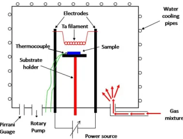
FIGURE 11 - HOT-FILAMENT REACTOR USED ... 34
FIGURE 12 - SCHEMATIC OF THE HFCVD SYSTEM USED TO DEPOSIT THE DIAMOND FILMS ... 35
FIGURE 13 - FILAMENT SETUP INSIDE THE CVD REACTOR ... 36
FIGURE 14 - SCHEMATIC REPRESENTATION OF THE TIME-MODULATED CVD PROCESS ... 38
FIGURE 15 - EMISSION OF ELECTRONS AND PHOTONS AS A RESULT OF THE BOMBARDMENT OF A SAMPLE WITH AN ELECTRON BEAM (ADAPTED FROM[85]) ... 39
FIGURE 16 - RAYLEIGH AND RAMAN SCATTERING AS A RESULT OF THE INTERACTION OF LIGHT WITH A MOLECULE (ADAPTED FROM [89]) ... 41
FIGURE 17 - QUANTUM REPRESENTATION OF ENERGY EXCHANGE IN THE NON-RESONANT RAMAN PHENOMENON (ADAPTED FROM [89]) ... 42
FIGURE 18 - SCHEMATIC REPRESENTATION OF THE SPECTROSCOPY TECHNIQUES USED. ADAPTED FROM [105] ... 49
FIGURE 19 - INDENTATION AND THE APPEARANCE OF CRACKS ... 53
FIGURE 20 - FILMS ROUGHNESS MEASUREMENT PRINCIPAL ... 54
FIGURE 21 - SCHEMATIC DRAWINGS OF THE ADAPTED MOLD TOOL (LEFT) AND THE MOLDED POLIMERIC PART (RIGHT) ... 55
FIGURE 22 - TMCVD DEPOSITION CONDITIONS USED ... 60
FIGURE 23 - SEM IMAGES OF DIRECT DIAMOND DEPOSITION ONTO STEEL USING CONVENTIONAL CVD (LEFT) AND TMCVD (RIGHT) ... 61
FIGURE 24 - SEM IMAGE OF A 17H DEPOSITION DIRECTLY INTO STEEL ... 61
FIGURE 25 - SEM IMAGE OF THE CARBON DIFFUSION INTO THE SUBSTRATE OF SAMPLE DCA01, DCA02, DCA03, DCA04, DCA05 AND DCA06 AFTER CARBON CVD DEPOSITION ... 64
FIGURE 26 - RELATIVE CONCENTRATIONS OF HYDROGEN, CARBON, C2 AND FE DEPTH PROFILE OF SAMPLES DCA01, DCA03 AND DCA04, BY SIMS ... 66
FIGURE 27 - X-RAY DIFFRACTION OF THE DIFFUSION SAMPLES ... 67
FIGURE 28 - RAMAN SPECTRUM OF THE TESTS SAMPLES ... 67
FIGURE 29 - VICKERS MICRO-HARDNESS ... 68
FIGURE 30 - ROCKWELL A HARDNESS ... 68
FIGURE 31 - SEM IMAGES OF DIAMOND DEPOSITION ONTO STEEL WITH TITANIUM INTERLAYER USING CONVENTIONAL CVD (LEFT) AND TMCVD (RIGHT) ... 70
FIGURE 32 - SEM IMAGES OF DIAMOND DEPOSITION ONTO STEEL WITH CHROMIUM NITRIDE INTERLAYER USING CONVENTIONAL CVD (LEFT) AND TMCVD (RIGHT) ... 70
FIGURE 33 - TIME-MODULATED CVD CONDITIONS USED ... 72
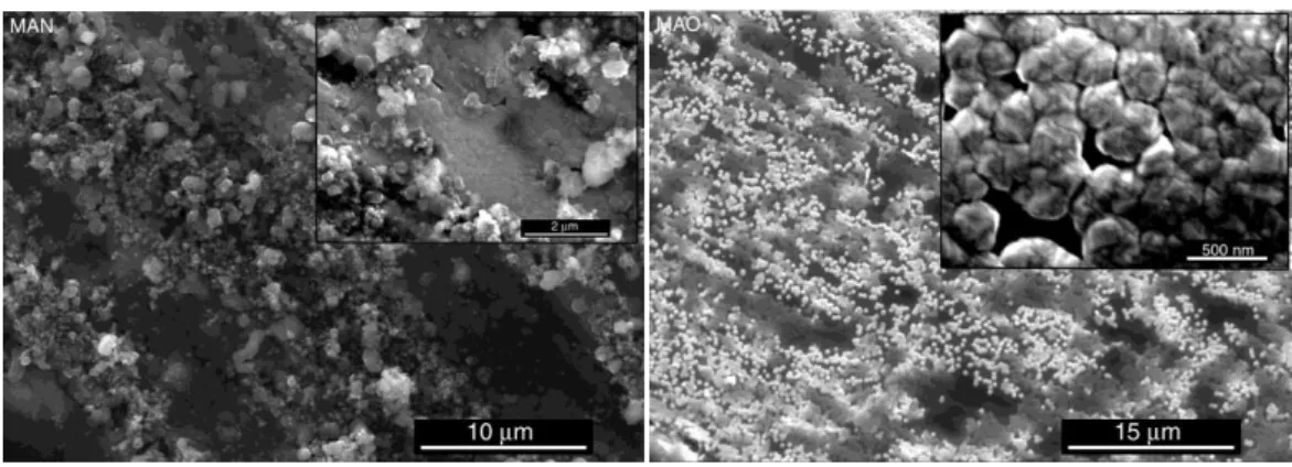
FIGURE 34 - SEM IMAGES OF DIAMOND DEPOSITION ONTO AISI 304 STEEL WITH CHROMIUM NITRIDE INTERLAYER USING DEP1 (LEFT) AND DEP4 (RIGHT) ... 73
FIGURE 35 - SEM IMAGES OF DIAMOND DEPOSITION USING DEP1 ONTO AISI 310 STEEL (LEFT) AND ONTO AISI 316 STEEL (RIGHT) WITH CHROMIUM NITRIDE INTERLAYER ... 74
FIGURE 36 - SEM IMAGES OF DIAMOND DEPOSITION ONTO AISI P20 MODIFIED STEEL WITH CHROMIUM NITRIDE INTERLAYER USING DEP1 (UP-LEFT), DEP2 (UP-RIGHT), DEP3 (DOWN-LEFT), DEP4 (DOWN-RIGHT) ... 75
FIGURE 37 - SEM AND X-RAY PROFILE AND MAP OF A P20 MODIFIED STEEL SAMPLE WITH A CRN INTERLAYER ... 76
FIGURE 38 - CROSS-SECTION SEM IMAGES AND EDS MAPS OF DIAMOND DEPOSITION ONTO AISI 304 STEEL WITH CHROMIUM NITRIDE INTERLAYER USING DEP4 (UP) AND ONTO AISI P20 MODIFIED STEEL WITH CHROMIUM NITRIDE INTERLAYER USING DEP1 (DOWN) ... 77
FIGURE 39 - SEM IMAGES OF AS-DEPOSIT DIAMOND FILM ON SAMPLES DC1, DC2, DC3 AND DC4 ... 79
FIGURE 40 - RAMAN SPECTRUM OF THE DIAMOND COATINGS OF SAMPLES DC1, DC2, DC3 AND DC4 ... 80
FIGURE 41 - TOF-SIMS DEPTH PROFILE OF SAMPLE DC1, DC2, DC3 AND DC4 ... 82
FIGURE 42 - EDS OF SAMPLES DC1, DC2, DC3 AND DC4 ... 83
FIGURE 43 - ROCKWELL C HARDNESS MEASURED VALUES FOR SAMPLES DC1, DC2, DC3 AND DC4 ... 83
FIGURE 44 - SEM IMAGES FROM BRINELL INDENTATIONS AT 187.5 KGF ON AISI P20 MODIFIED SAMPLES AFTER CYCLE DEP2 (LEFT) AND DEP3 (RIGHT) ... 84
FIGURE 45 - SEM IMAGES FROM BRINELL INDENTATIONS OF A SAMPLE OF AISI 304 AFTER CYCLE DEP4 AT 20 KGF (LEFT) AND AT 50 KGF (RIGHT) ... 84
FIGURE 48 - MOULD CAVITY (LEFT) AND CLOSE-UP OF THE DIAMOND-COATED INSERT PLATE (RIGHT) ... 91
FIGURE 49 - SEM IMAGE OF THE AS-DEPOSITED DIAMOND FILM ... 91
FIGURE 50 - HIGH-DENSITY POLYETHYLENE (HDPE) INJECTED PLATE ... 92
FIGURE 51 - SEM IMAGES OF THE DIAMOND FILM AFTER THE ROUTINE INJECTION CYCLE AT HIGH MAGNIFICATION (TOP) AND LOW MAGNIFICATION (BOTTOM) ... 93
FIGURE 52 - EDS OF THE DIAMOND FILM ... 94
FIGURE 53 - BRINELL HARDNESS OF THE STEEL SUBSTRATE, OF THE STEEL SUBSTRATE-COATED WITH CRN AND THE STEEL SUBSTRATE WITH CRN INTERLAYER AND DIAMOND COATED ... 95
FIGURE 54 - SEM IMAGES OF BRINELL HARDNESS INDENTATIONS, USING A 2.5 MM STEEL SPHERE AND LOADS OF 613 N, 490 N, 306.5 N AND 153.2 N ... 96
FIGURE 55 - SEM IMAGES OF BRINELL HARDNESS INDENTATIONS BOUNDARY ZONE, USING A 2.5 MM STEEL SPHERE AND LOADS OF 613 N, 490 N, 306.5 N AND 153.2 N... 96
FIGURE 56 - RAMAN SPECTRUM OF THE DIAMOND COATING BEFORE AND AFTER BRINELL INDENTATION AT 613 N (IN THE CENTRE, IN THE MIDDLE AND IN THE BOUNDARY OF THE INDENTATION) ... 97
FIGURE 57 - SEM IMAGES OF VICKERS MICRO-HARDNESS INDENTATIONS USING A LOAD OF 0.49 N, 0.98 N AND 1.96 N FOR 10 S AND 5 S ... 98
FIGURE 58 - TIME-MODULATED CVD CONDITIONS USED ... 99
FIGURE 59 - SEM IMAGES OF INSERTS AC1 (TOP LEFT), AC2 (TOP RIGHT), AC3 (BOTTOM LEFT) AND AC4 (BOTTOM RIGHT) BEFORE INJECTION MOLDING ... 100
FIGURE 60 - EDS OF THE MOLDING INSERTS ... 100
FIGURE 61 - OPTICAL MICROSCOPY IMAGES OF THE HDPE MOLDED SURFACES ... 101
FIGURE 62 - SEM IMAGES OF INSERTS AC1 (LEFT) AND AC2 (RIGHT) AFTER 500 INJECTION MOLDING ... 102
FIGURE 63 - DIAMOND DEPOSITION CONDITIONS ... 103
FIGURE 64 - SEM IMAGES OF DIAMOND COATINGS ON STEEL SUBSTRATES SAMPLE FD1 (TOP), FD2 (MIDDLE) AND FD3 (BOTTOM) ... 105
FIGURE 65 - RAMAN SPECTRA OF THE DIAMOND-COATED STEEL PLATES ... 105
FIGURE 66 - OPTICAL MICROSCOPIC IMAGES OF THE HDPE-INJECTED PLATE SURFACE, BY THE DIFFERENT INSERTS, IN RUN NUMBER 1, 50 AND 80 ... 106
FIGURE 67 - SEM IMAGES OF DIAMOND COATINGS ON STEEL SUBSTRATES AFTER HDPE MOULDING INJECTION SAMPLE FD1 (TOP), FD2 (MIDDLE) AND FD3 (BOTTOM) ... 107
FIGURE 68 - SCHEMATIC DRAWINGS OF THE ADAPTED MOLD TOOL (LEFT) AND THE MOLDED POLIMERIC PART (RIGHT) ... 108
FIGURE 69 - IMAGE OF THE 3D INSERTS ON THE MOLD TOOL ... 109
FIGURE 70 - SEM IMAGES OF INSERTS AD1 (LEFT) AND AD2 (RIGHT) AS DIAMOND COATED ... 109
FIGURE 71 - SEM IMAGE OF THE DIFFERENT REGIONS OF THE 3D FEATURES ON INSERTS AD1 AND AD2, AS-DEPOSITED... 110
FIGURE 72 - MOLDED PLASTIC PLATE ON RUN 400 ... 111
FIGURE 73 - DEGRADATION OF THE FEATURE HEIGHT ... 111
FIGURE 74 - SEM IMAGES OF INSERTS AD1 (LEFT) AND AD2 (RIGHT) AFTER 500 INJECTION MOLDING ... 112
FIGURE 75 - SEM IMAGE OF THE DIFFERENT REGIONS OF THE 3D FEATURES ON INSERTS AD1 AND AD2, AFTER INJECTION MOLDING ... 112
FIGURE 76 - SEM IMAGES OF DIAMOND COATINGS ON SILICON SUBSTRATES SAMPLE SD1 (TOP), SD2 (MIDDLE) AND SD3 (BOTTOM) ... 115
FIGURE 77 - RAMAN SPECTRUM OF THE SILICON-COATED STEEL PLATES... 115
FIGURE 78 - OPTICAL MICROSCOPIC IMAGES OF THE HDPE-INJECTED PLATE SURFACE, BY THE DIFFERENT INSERTS, IN RUN NUMBER 1, 50 AND 80 ... 116
FIGURE 79 - SEM IMAGES OF DIAMOND COATINGS ON SILICON SUBSTRATES AFTER HDPE MOLDING INJECTION SAMPLE SD1 (TOP), SD2 (MIDDLE) AND SD3 (BOTTOM) ... 117
TABLE 2 - CYCLIC REACTIONS LEADING TO THE DIAMOND DEPOSITION 17
TABLE 3 - MECHANICAL AND THERMAL PROPERTIES OF DIAMOND [17, 19, 24] 19
TABLE 4 - SUMMARY OF INTERLAYERS USED FOR DIAMOND DEPOSITION ON STEELS 25
TABLE 5 - RAMAN SCATTERING OF CARBON MATERIALS 44
TABLE 6 - DIAMOND, CRN AND FECR CRYSTALLOGRAPHIC DATABASE [104] 48
TABLE 7 - PARTICULAR DETAILS OF HRA, HRB AND HRC ROCKWELL SCALES [107] 52
TABLE 8 - CYCLE INJECTION MOLDING PROCESSING CONDITIONS 56
TABLE 9 - DEPOSITION CONDITIONS 60
TABLE 10 - DEPOSITION CONDITIONS 62
TABLE 11 - EXPERIMENTAL DETAILS 62
TABLE 12 - MEASURED MASS INCREASE AND DIFFUSION DEPTH 64
TABLE 13 - CHEMICAL COMPOSITION OF THE AISI 310 AND 316 STEELS [69] 74
TABLE 14 - INTERLAYER THICKNESS 78
TABLE 15 - DIAMOND DEPOSITION CONDITIONS 78
TABLE 16 - RAMAN SHIFT OF THE DIAMOND PEAK, CALCULATED RESIDUAL STRESS AND RAMAN QUALITY FACTOR 80 TABLE 17 - BRINELL HARDNESS, INDENTATION DEPTH, INDENTATION DIAMETER-DEPTH RATIO DETERMINATION AND
OBSERVABLE CRACKS 85
TABLE 18 - DIAMOND DEPOSITION CONDITIONS 90
TABLE 19 - CYCLE INJECTION MOULDING PROCESSING CONDITIONS 92
TABLE 20 - DESCRIPTION OF THE DIFFERENT INSERT MOLD TOOLS 99
TABLE 21 - DESCRIPTION OF THE DIFFERENT INSERT MOLD TOOLS 104
TABLE 22 - DESCRIPTION OF THE DIFFERENT INSERT MOLD TOOLS 109
Abbreviations
3D Three-dimensional
AISI American Iron and Steel Institute CVD Chemical Vapor Deposition
DIN Deutsches Institut für Normung e.V. (German Institute for Standardization) EDS Energy Dispersive X-ray Spectroscopy
F Helmholtz free energy HB Brinell hardness number
HFCVD Hot-filament Chemical Vapor Deposition HR Rockwell hardness number
HV Vickers hardness number
I Raman intensity
N Number of particles
n Number of atoms or molecules OM Optical Microscopy
Pc crystal pressure
Pv Vapor pressure
Q Quality factor
S Crystal surface
SEM Scanning Electron Microscopy SIMS Secondary Ion Mass Spectrometry
T Temperature
TMCVD Time-modulated Chemical Vapor Deposition
V Volume
XRD X-ray Diffraction Spectroscopy
Y Young's modulus Chemical Compounds Ar Argon CH3 Methyl CH4 Methane Cr Chromium CrN Chromium Nitride Fe Iron H Atomic hydrogen H2 Hydrogen Ni Nickel Si Silicon Ta Tantalum
TaC Tantalum Carbide
Ti Titanium
Greek letters
Frequency
Raman peak/band center
Stress
Poisson's ratio
Coefficients of thermal expansion
P Molecule polarizability
t Surface tension
µ Chemical potential
Energy 1 eV = 1.6022 x 10 J 1 cm-1 ≈ 8 meV
Flow 1 sccm = 1 ml/min (milliliter/minute)
Force 1 kgf = 9.807 N (Newton)
Length 1 Å = 0.1 nm (nanometer) = 1×10⁻¹⁰ m (meter) Pressure 1 Torr = 133.3224 Pa (Pascal)
1 Torr = 1.333224 mbar (milibar) 1 kgf/mm2 = 9.807x10⁶ Pa
Chapter 1
Introduction
1 Thermoplastic injection molding and tools
Injection molding is a manufacturing technique to produce parts, as the ones showed in figure 1, from thermoplastic and thermosetting polymers. It consists of a cyclic process in which a melted (plasticized) polymer is injected into a mold cavity or cavities (impression), where it is held under pressure until it is removed in a solid state, thus duplicating the impression of the mold. [1]
Typically, polymers or plastics (as they are commonly named) are defined as materials which can be molded or shaped into different forms under the influence of pressure and heat. Chemically, polymers are substances composed of long chains of repeating molecules, called monomers, made up predominantly of carbon and hydrogen atoms, which under the desirable conditions, connect together to form chain structures. In addition to carbon and hydrogen, oxygen, nitrogen, chlorine, and other elements may be found in some polymers. [2]
The main difference between thermoplastics and thermosetting polymers is that the first ones may become soft, remoldable and weldable when heated. Thermosetting polymers however cannot be welded or remolded when heated.
Figure 1 - Plastic molded objects
Three basic operations take place in the thermoplastic injection molding process: (i) heating the thermoplastic in the injection or plasticizing unit, so that it will flow under pressure; (ii) allowing the thermoplastic melt to solidify in the mold cavity or cavities; and (iii) opening of the mold to extract the molded product. These three steps are the operations in which the mechanical and thermal inputs of the injection equipment must be coordinated with the fundamental properties and behavior of the thermoplastic being processed. Figure 2 presents a picture of an Inauton D65 injection molding machine and figure 3 some mold tools for thermoplastic molding.
Different thermoplastics may display different characteristics, performances and will carry a different cost. The characteristics and performance are influenced by factors such as molecular size and weight, molecular distribution, and shapes or structures of individual molecules. Properties and behavior are also influenced by compounding of different amounts and combinations of additives (colorants, flame retardants, heat and light stabilizers, etc.), fillers (calcium carbonate, etc.), and reinforcements (glass fibers, glass flakes, graphite fibers, whiskers, etc.) that are used with plastics. Compounding also embraces the mixing (alloying, blending, etc.) of two or more plastics that may be miscible or immiscible, with or without additives.
Figure 2 - Inauton D65 injection molding machine
Molding tools or molds are the production tools used to produce polymer parts in injection molding. The mold is probably the most important part of the injection molding process. It is a controllable, complex and expensive device. If it is not properly designed, operated, handled, and maintained its operation will be costly and highly inefficient.
Under pressure, hot melt moves rapidly through the mold. During the injection into the mold, air in the cavity or cavities is released to prevent melt burning and the formation of voids in the product. Temperature-controlled cooling media (i.e. water, oil, etc.) circulates in the mold to remove heat.
The mold basically consists of a sprue, a runner, a cavity gate, and a cavity (impression). The sprue is the channel located in the stationary platen that transports the melt from the plasticator nozzle to the runner. In turn, melt flows through the runner and gate and into the cavity. With a single-cavity mold, usually no runner is used, so melt goes from the sprue to the gate. Different runner systems are in use to meet different processing requirements. The most popular are cold and hot runners. With a cold runner, the melt flowing from the sprue to the gate solidifies by the cooling action of the mold as the melt in the cavity or cavities solidifies. With a hot runner the sprue to the gate is insulated from the chilled cavity or cavities and remains hot, so that the melt never cools; the next shot starts from the gate, rather than from the nozzle as in a cold runner.
Molds are provided with different means, such as sliders, unscrewing devices, undercuts and extraction systems to eject products as well as solidified runners at the proper time. These basic operations require control of various parameters such as fill time and hold pressure. Molds are typically constructed from hardened steel, pre-hardened steel, aluminium, and/or beryllium-copper alloy.
2 The worldwide molds industry – an overview
Plastics can be divided into natural, semi-natural and synthetic plastics. Natural plastics include amber, horn, tortoiseshell and bitumen, and were used in the most ancient civilizations. The ancient Egyptians molded amber into items such as jewelry. [2]
John Wesley Hyatt, an American inventor, was the first to inject hot celluloid (a semi-natural polymer) into a mold, using an injection molding machine, producing billiard balls, in 1868. He and his brother Isaiah, patented an injection molding machine that used a plunger in 1872. The first screw injection molding machine was built on 1946 by James Hendry, revolutionizing the
plastics industry. Roughly 95% of all molding machines now use screws to efficiently heat, mix, and inject plastic into molds. [3]
The use of polymers to produce manufactured goods boosted since the boom appearance of synthetic polymers and with the end of the Second World War. The British plastic industry passed from selling 50 000 tons in 1939, to 160 000 in 1950, and to 550 000 tons in 1960, and have continued to grow since. [2]
Portugal is an international leader in the molds industry. It is the eighth-largest producer of dies and molds in the world and it exports to more than 70 countries. Portugal is also one of the world’s principal producers of precision molds for the plastics industry. Many multinational corporations recognize the industry’s excellence and increasingly choose Portuguese suppliers for their molding requirements due to their experience, skills, delivery times and pioneering use of advanced technologies. The industry has more than 500 companies active in Portugal, working in different specialized areas with specific molds techniques, from simple services to highly complex molds production. [4-6]
In the late 18th century an Englishman named William Stephens opened a glass-making plant in the town of Marinha Grande, the Fábrica Escola Irmãos Stephens, employing artisans from Genoa and Lisbon. The skill of the town's glassworkers came to rival the best in the world and the town still remains today the "glass capital" of Portugal. [7]
At the beginning of the 20th century, Marinha Grande began producing molds for glassware, having previously imported them from Germany and Austria. This was the foundation for the growth of the plastics molds industry. Aníbal H. Abrantes, a partner and lathe-worker in the first pressed glass molds plant in Marinha Grande, established the first molds plant for Bakelite products in 1944. Two years later Abrantes produced Portugal's first plastic injection mold. Other plastics mold companies began to open in Marinha Grande and in the northern town of Oliveira de Azeméis, another traditional glassmaking centre. The industry developed with the importation of foreign technology. Exports began in 1955 with the sale of the first Portuguese mold to Britain. By 1980, in the Marinha Grande area alone 64 companies employing 2000 people were operational. [7]
Today, the molds sector in Portugal employees about 7500 people, in more than 500 companies, most of them in the Marinha Grande area. Most of these companies are small to medium-sized, employing an average of 30 workers. [4, 6, 7]
The dynamism and commercial drive of Portuguese molding industry are recognized internationally for its competitiveness in quality, delivery times, technological capacity and
price. This worldwide reputation has enabled Portuguese mold makers to establish a presence in more than 70 countries. [7]
The industry exports about 90% of its production. These exports earned around € 369 million in 2006. In this year, and maintaining the trend of the last 3 years, the main exports destinations were France, Spain, Germany, United Kingdom and the United States of America, as it can be seen in figure 4. Automobile industry sector by itself accounted for approximately 78% of the molds produced. Other relevant sectors are electrical domestic appliances, packing, and domestic tools, as presented in figure 5. [4]
Nevertheless, the Portuguese mold making industry, as the European, is coming under increasing economic pressure from the Pacific Rim countries, which can supply tooling more cheaply. To slow down or reverse the decline in the Small and Medium based EU tooling industry, processes that offer mold makers a competitive advantage over non-EU imports are required.
Figure 4 - Main export destinations of Portuguese molds in 2006 [4] France; 19% Spain; 15% Germany; 14% UK; 8% USA; 8% Mexico; 3% Sweden; 3% Romania; 3% Argentina; 2% Others; 25%
Figure 5 - Main industries supplied in 2006 [4]
An American report on Competitive Conditions in the United States and Selected Foreign Markets of Tools, Dies, and Industrial Molds by the United States International Trade Commission (United States International Trade Commission, 2002) pointed out that the Portuguese mold making unique industry characteristic to be composed of small industry dedicated almost exclusively to exporting. The same report also highlighted the strengths to be: specialist training colleges; quick lead times (time required to produce a die or mold), technological capability, price, and low labor costs; quality, technology, service, skilled in producing high precision and complex dies and molds. And the weaknesses: small domestic market with lowest productivity indicators (sales per worker) among International Special Tooling and Machining Association members; lacks modern automotive and aerospace industries to stimulate technological advancement; and many die and mold producers tend to be small companies with limited financial and management resources.
New value strategies are being proposed and carried out [8, 9]. The integration of the mold tool in a high-tech engineering chain, that is not limited to the mold tool production, but assists from its conception to the end of its service, enlarges the intervention period of the molding system provider, reducing the importance of the mold production cost. A different or complementary business strategy is the specialization in high complexity mold with top pioneering and engineering solutions.
In both strategies, the technology knowledge must be enlarged and network partnerships between complementary enterprises, R&D institutions and prime clients must be considered.
Automobile ; 78% Electrical domestic appliances; 5% Packing; 6% Domestic tools; 5% Electronic; 5% Medicine; 1%
Increased tool functionality and productivity during component processing, decreased tool cost, wider range of tool application, reduced environmental, health and safety impact during both tool and component manufacture, and extended tool longevity and reduced maintenance times are key parameters for future strategies. [8, 9]
3 Industry challenge
As pointed in the previous section, the implementation of new value strategies implies challenges for the mold making industry, namely the improvement of technology comprehension. One of the main goals of the present doctoral thesis is to modestly contribute to the latter.
Microsystems-based products will be an important contributor to the industrial and economic future, as a key value adding element for many sectors of industry — and the predicted nanotechnology future will also be largely delivered by microtechnologies. The 21st century will most surely adopt micro and nano manufacturing technologies making use of a variety of materials, components and knowledge based technologies that provide functionality and intelligence to highly miniaturised systems. [10]
Machining has been the only feasible manufacturing alternative for manufacturers sourcing low to moderate quantities of micro components. The process of micro molding has been in existence for over 20 years, but because of the modest volumes or the complexity of the components it has often been avoided. However, in the last five years, with the advances in materials, processing and measurement techniques, micro molding can offer a range of cost-effective alternatives for components that are miniatures, complex and require high precision tolerances. [11, 12]
Machining places limitations on the material selection process where high-cost ceramics or engineered metallic materials are commonly used. As a result, sourcing low to moderate volume micro components has been a costly challenge for manufacturers. Advances in material science and plastic injection molding equipment permit complex machined micro components to be injection molded in metal, plastic, or plastic with metal or ceramic filler. Molded micro-switch plungers are shown in figure 6. There are a number of cost and design advantages that can be obtained by converting to injection molding. Engineers looking to decrease the overall size of their product, to incorporate complex features, to reduce the
Figure 6 - Mini Micro-switch Plunger [11]
number of components, or to reduce costs should consider micro molding as an alternative to machining. [12]
Plastic microinjection molding tools can clearly be seen as an added value strategy specialization, with a high complexity and top pioneering and engineering solutions requirements.
There are a number of benefits that can be achieved by converting to micro molding. One advantage is that the amount of time it takes to mold a component is a fraction of what it takes to machine a component. Another is particle contamination. Designers do not want to have the possibility of foreign matter being introduced into their fluid-carrying medical devices, for example. Micro molding eliminates the potential failure mode of having particulates left after machining and enables better surface finishing. Micro molding also gives more freedom to designers to place intricate features in products thereby enhancing their ability to create more innovative products. As the trend for smaller components becomes greater, it might become more difficult to machine complex geometries making micro molding the only option. In addition, micro molding also offers a dimensionally stable production process and improvement of mechanical and/or electrical properties using alternative resins or fillers. [12]
Although the advances acquired in the past couple of years in the microinjection molding technology process, there are still some problems on the downstream that must be overcome. Micro moldings may become statically charged and tend to adhere to surfaces around the molding area, making free fall extraction difficult or even impossible.
In the conventional thermoplastic injection molding, the wear of molding tools is known to be one of the main sources of breakdown failures, resulting in production losses [13]. In microinjection of thermoplastic parts, molds for components that are miniature, complex and require high precision tolerances are not wear free, on the contrary, the cavity wear can be even much more critical than in conventional molding [11, 12].
Issues such as aspect ratio have to be considered carefully, as fine details that can approach micron levels of dimension must be capable of withstanding cavity pressures created during the injection phase. The wear out of the molding tools creates demolding problems, compromising the polymeric parts finishing quality, speeding up the corrosion of the tools, and result in maintenance stops. Most of the mold tools have complex geometries and complex moving parts which favor the corrosion and wear mechanisms. Polymer abrasion, adhesion and corrosion are the catalyzers of these mechanisms. Furthermore, the increasing usage of polymers reinforced with glass fibers, minerals, or even carbon nanotubes, enhance the abrasive power of polymers. [14]
In terms of mold design, new materials are being developed with high coefficients of thermal conductivity, and coatings can be applied to assist part removal without damage.
Hard chrome and nickel plating are currently the most commonly employed method of treating the surface of conventional mold tools to improve durability. Although plating is an effective technique it does suffer from a number of attendant problems. Most significantly, all commercial chromium plating baths utilize CrVI, which is highly toxic and is hazardous to the environment and the user, requiring careful monitoring and legislated control. Nickel plating, although not as hazardous as Cr plating, still releases significant emissions into the environment. From a technical standpoint electrodeposited Cr coatings are inherently micro-cracked, resulting in poor corrosion resistance and spalling. Two further hard coating techniques of note are Physical Vapor Deposition and the Thermal Diffusion process and its variants. Both are used to deposit nitrides onto tools (particular TiN, CrN and NbN) but again these processes are severely limited by the size of the application cell. [14]
Chemical Vapor Deposition of polycrystalline diamond, in microcrystalline or nanocrystalline morphology, detains a number of extreme properties that point it as a technology suitable for
exploitation in numerous industrial applications. It possesses an extreme mechanical hardness and wear resistance, one of the highest bulk modulus, the lowest compressibility, the highest room temperature thermal conductivity, a very low thermal expansion coefficient at room temperature and is very resistant to chemical corrosion (see table 3). Most of these properties are attractive for cavities and molding tools.
The application and evaluation of CVD diamond thin films as a surface engineering to improve operation and durability of mold tools will be the prime objective of this doctoral thesis.
Chapter 2
Diamond CVD coatings
1. Introduction
Diamond is considered an ideal material for many applications due to its extreme properties. It is a metastable carbon polymorph at room temperature and atmospheric pressure. Its crystal structure belongs to the space group1 Oh7 (F4, /d 32/m) with two atoms per primitive Bravais cell. Its structure can be viewed as two interpenetrating face centered cubic lattices shifted along the body diagonal by 14,14,14 𝑎 2, where 𝑎 is the dimension of the cubic (mineralogical) unit cell, as shown in figure 7. Each carbon atom has a tetrahedral configuration consisting of sp3 hybrid atomic orbitals3. The 111 4 crystallographic plane comprises 6-atom hexagonal rings arranged so that the adjacent atoms are alternately dislocated upward and downward from the plane. The stacking sequence in the 111 5 direction is ABCABCABC. The lattice constant is 3.56 Å and the bond length is 1.54 Å. Natural diamond consists of 98.9% 12C and 1.1% 13C. The characteristic Raman spectroscopic signals for diamond are 1332 cm−1 for 12C and
1 The space group of a crystal or crystallographic group is a mathematical description of the symmetry
inherent in the structure.
2 The notation 𝑙𝑚𝑛 denote planes orthogonal to a direction 𝑙, 𝑚, 𝑛 in the basis of the reciprocal lattice
vectors. 𝑙, 𝑚 and 𝑛 are the Miller indices that are a notation system in crystallography for planes and directions in crystal (Bravais) lattices.
3
Hybridization, in chemistry, is the concept of mixing atomic orbitals to form new hybrid orbitals suitable for the qualitative description of atomic bonding properties. The hybridization theory was promoted by chemist Linus Pauling in order to explain the shape of molecular orbitals for molecules.
4 The notation 𝑙𝑚𝑛 denotes all planes that are equivalent to 𝑙𝑚𝑛 by the symmetry of the crystal. 5 The notation 𝑙𝑚𝑛 denotes all directions that are equivalent to 𝑙𝑚𝑛 by symmetry. 𝑙𝑚𝑛 denotes a
1284 cm−1 for 13C. A typical unit cell for the diamond cubic crystal structure can be seen in figure 7. [15, 16]
Carbon has two isomers. The first isomer is lonsdaleite found in meteorites. The positioning of atoms in each plane of the structure of lonsdaleite is the same as that in the cubic structure. However, the planes are linked in a manner which results in a stacking sequence of ABABAB. Consequently, the atoms experience closer chemical bonding, with lattice constants in the a and c directions of 2.52 and 4.12 Å, respectively. The distance between adjacent atoms is 1.52 Å. The corresponding Raman peak is in the range of 1315–1325 cm−1. Another isomer is graphite, the most common form of carbon. Each carbon atom has a sp2 atomic configuration and therefore, three in-plane sigma bonds. The remaining valence electron forms π bonds using a pz atomic orbital. Thus, the trigonally bonded 6-carbon rings are situated in a flat plane instead of being in alternate order plaited as in diamond. The planes are layered in an ABABAB sequence. The lattice constant in the basal plane between repeating layers is 6.707 Å, and the in-plane, nearest neighbor spacing is 1.42 Å. The signature Raman peak of the in-plane layers is 1580 cm−1. [15]
Figure 7 - Unit cell for the diamond cubic crystal structure
2. History and developments
The modern use of impregnated tools, which consume the vast majority of the industrial diamond used today, is probably a century old, and most of the growth witnessed by the industry has taken place in the last fifty years. However, diamond has been recognized as being a unique material for several centuries. Originally recognized for its spectacular cosmetic properties and found in southern India, its early use as an industrial tool was confined to that of engraving. Asian references to the cutting of the very hard jade stone can be traced back to
300 BC and possibly further. In the 18th century French philosopher Diderot described the use of a hand-held diamond tool for drilling stone. By the mid 1800s this had developed considerably, and diamond rock drills were powered by machines.
The very early developments in diamond tools took place relatively slowly, as presented in table 1. When only natural diamond was available, the development of new applications using diamond was largely self-defeating, since the more material they consumed, the less feasible they were in terms of world supply due to shortage of raw material.
The scenario changed noticeably in the 1950s when innovation changed to invention and synthetic diamond became a commercial reality. Large presses simulate the conditions of high pressures and temperatures that created natural diamond deep within the crust of the earth and through the application.
The first CVD diamond growth under low pressures was reported by Spitsyn and Deryagin from the Physics and Chemistry Institute of Moscow, in 1956 and by Eversole from the Union Carbide Corporation (USA), in 1962. Their method consisted of a cyclic pyrolysis, where diamond was used as a substrate and diamond growth occurred homoepitaxially. This method was further expanded by Angus et al. and Derjaguin et al. in the early 1970s. However, since
Table 1 - Chronology of diamond utilization [17, 18]
Date Event
340 BC Aristotle describes the use of diamond tipped drills in Greece.
1000s Pliny describes the use of diamond splinters in handles of iron to form an engraving tool in Italy. Reports describe the use of a diamond engraving tool called jade cutter knife in China.
1400s Crushed diamond powder used for polishing diamond.
1500s Leonardo da Vinci reports the use of diamond tools for glass cutting. 1600s Report on the first diamond drilling tool.
1700s Ramsden reports the first single diamond turning tool for application in metal working. Smith-Tennant reports diamond to be composed solely of carbon.
1800s Diamond grinding wheels are being used by Pritchard in England to shape lenses. France grants a patent for a diamond core drill for use in the French stone industry. Use of diamond as a wire drawing die.
Diamond drills for dentistry are introduced in the USA by Desau. 1900s Wheel for glass grinding developed by Carl Zeiss Jena.
First description of grinding tungsten carbide with diamond.
First successful diamond synthesis via High Pressure, High Temperature by ASEA, Sweden (February
16th, 1953).
Shockwave sintering of diamond reported.
Natural diamond used as heat spreaders for semiconductors. First large synthetic diamond crystals grown up to 0.25 cts in weight. Polycrystalline diamond launched commercially.
Growth of diamond crystals via low pressure CVD on non-diamond substrates announced in the Soviet Union.
Sales by volume of synthetic diamond products exceeds natural diamond for the first time. 2000s Development of high quality single crystal CVD diamond for electronic applications.
cyclic, hydrocarbon pyrolysis had a very slow diamond deposition rate (1 - 10 nm/h) and required a diamond grit substrate, its application was unrealistic. [15, 19]
In 1982, Matsumoto et al. made a breakthrough in CVD diamond technology. They used hot filaments (at 2000 °C) to directly activate hydrogen and hydrocarbon which were passed through the hot filament. The diamond film was then deposited onto a non-diamond substrate located 10 mm away from the filament. Graphite was etched simultaneously by atomic hydrogen during deposition which rendered the cycling of deposition and etching unnecessary and therefore led to a higher growth rate (1 µm/h). [20]
Thermodynamically, the crystal growth process is a matter of chemical potential equilibrium between two systems: the environment in the reactor chamber and the crystallites. Chemical potential governs the flow of particles between the systems. If two systems have different chemical potential, particles will flow from the system at the higher chemical potential to the system at lower chemical potential. Chemical potential, µ, is a function of the system temperature, T, volume, V, and number of particles, N, and is defined as:
𝜇 𝑇, 𝑉, 𝑁 ≡ 𝑑𝐹
𝑑𝑁 𝑇,𝑉 (1)
where F is the Helmholtz free energy. [21-23]
Applying the chemical potential concept [23], with the Laplace equation:
𝑃𝐶− 𝑃𝑉= 2𝜎𝑟𝑡 (2)
where t is the surface tension of the crystal and r is the body radius (considering a crystal with a shape similar to a droplet) and the product 2 𝜎𝑟𝑡 is known as the Laplace pressure, and with the Thomson-Gibbs equation:
𝜇𝑉− 𝜇𝐶 = 2𝜎𝑡𝑉𝐶
𝑟 (3)
it can be supposed that volume, Vc, is gained when transferring n atoms or molecules from the supersaturated ambient phase (vapor), with higher chemical potential, µv, to the crystal phase with lower bulk chemical potential, µc:
𝑃𝐶− 𝑃𝑉 𝑉𝐶 = 𝑛 𝜇𝑉− 𝜇𝐶 (4)
where Pv is the vapor pressure and Pc is the crystal pressure.
Nevertheless, to be able to promote the crystal growth it is required the appearance of small clusters of building units (atoms or molecules) in the volume of the supersaturated ambient phase (nucleation sites).
The crystal shape is due to the equilibrium of a small crystal with its ambient phase, that leads to the formation of a particular shape which is the most favorable from a thermodynamic point of view, this is, when the work to form such crystal is at a minimum [23].
The surface requires a work equal to tS, where S is the crystal surface, to create a new phase-dividing surface.
The volume part depends on the crystal volume or the atoms transferred. At a constant volume, the surface part depends only on the crystal shape, tending for a minimum of surface energy or an equilibrium shape. Then the conditions for a minimum Gibbs free energy changes with the crystal formation at a constant volume.
If instead of a crystal, there is a liquid droplet, the equilibrium shape would be evidently a sphere. In the case of a crystal, equilibrium shape is not that simple, due to the different crystallographic orientations and different specific surface energies. The latter meaning that the surface energy depends on the crystallographic orientation and in that sense it is anisotropic.
The growth of a polycrystalline diamond film starts from distinct nucleation sites. As individual randomly oriented nuclei grow larger, its diameters equal the average distance between the nucleation sites and start to form a continuous film. The subsequent film growth is dominated by competitive growth between randomly oriented grains. With increasing film thickness, more and more grains are overgrown and buried by adjacent grains. Only those crystals with the direction of fastest growth perpendicular to the surface will survive.
As mentioned above, thermal or plasma energy is the key factor to promote the fluctuations of the density to achieve small aggregates and to promote the thermodynamic environment to lead to crystal growth. Nevertheless, it has been gradually recognized that the superequilibrium concentration of atomic hydrogen has also an important role on diamond growth. [19]
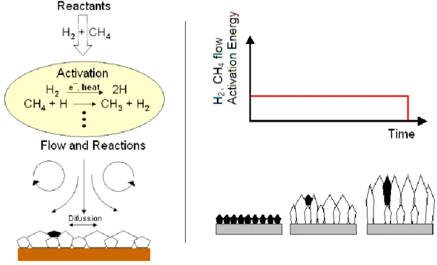
It is presently accepted that the growth of diamond crystals at CVD conditions, does not occur only due to a simple step process, but due to several stages and phenomena as presented in table 2 and figure 8.
Table 2 - Cyclic reactions leading to the diamond deposition
Stage Event
1st Activation of the gas mixture
2nd Transport of the active gas mixture to the substrate
3rd sp2 and sp3 simultaneous deposition
Figure 8 - Reactions taking place inside the CVD chamber during diamond growth
Various activating methods for diamond CVD such as DC-plasma, RF-plasma, microwave plasma, electron cyclotron resonance-microwave plasma CVD, and their modifications were developed.
A method also worthy of mention is the pyrolysis of fluorocarbons, such as CF4, that could produce epitaxial diamond growth. OH radicals, O2, O, F2, and F as graphite etchants are even better than atomic hydrogen.
Besides CVD, physical vapor deposition methods were also attempted and were expected to deposit diamond at low temperatures. Recent work has demonstrated that diamond nanocrystals in the matrix of amorphous carbon could be produced by direct low-energy ion bombardment using a mixture of CH4/H2/Ar ions. [15]
3. Properties and applications
Diamond exhibits a number of exceptional properties, as presented in table 3, which individually or in combination with other materials, makes it the potential application material for a range of industrial applications.
The strength of the carbon-carbon bond is the source of the exceptional mechanical properties of diamond. Dislocation of the atoms is difficult and consequently diamond is the hardest known substance.
It is chemically inert and due to the high strength of the covalent bonds it is highly resistant to chemical attack by acids or other chemical reagents. The only exceptions are materials that at high temperatures act as oxidizing agents - these provide the only effective way to attack diamond at normal pressures and temperatures (below about 1000 °C). Salts, such as sodium nitrate, are known to attack diamond when in the molten state at temperatures as low as 450 °C and, in oxygen itself, diamond starts to be oxidized at around 650 °C. The only other possible form of chemical attack is by two groups of metals. The members of the first group are strong carbide formers, and include tungsten, tantalum, titanium and zirconium. At very high temperatures, these will react chemically with diamond to form their respective carbides. The second group of metals includes iron, cobalt, manganese, nickel and chromium (and also the platinum group of metals). In the molten state these metals are true solvents for carbon. [17]
Table 3 - Mechanical and thermal properties of diamond [17, 19, 24]
Natural Synthetic Polycrystalline Thin Film Density (g/cc) 3.51 - 3.52 3.20 - 3.52 3.00 - 4.00 2.65 Volume Compressibility
(x 10-10 m²/N)
18.0 -- -- --
Coefficient of friction (dynamic) 0.03 0.03
Hardness, Knoop 8000 -- -- -- Microhardness, Knoop (GPa) 56.0 – 102 (001) face 58.0 - 88.0 (110),(111) face 54.0 - 84.0 49 - 78 65.0
Vickers Microhardness (GPa) 88.0 – 147 (001) face 98.0 (111) face 88.0 - 108 Type Ib 108 – 145 Type IIa 25.0 - 98.0 29.0 - 118 Hardness, Mohs 10.0 -- -- -- Abrasive Hardness 140000 -- -- --
Modulus of Elasticity (GPa) 700 - 1200 800 - 925 749 - 953 536 - 1035 Compressive Yield Strength
(MPa) 8680 - 16530 4500 - 5800 1900 - 6900 -- Poisson Ratio 0.100 - 0.290 0.200 0.0700 - 0.200 -- Fracture Toughness (MPa-m½) 3.40 6.00 - 10.7 6.00 - 8.80 --
Thermal Expansion Coef., linear (µm/m-°C)
1.18 -- 1.50 - 3.80 0.8 (at RT)
4.5 (at 800 °C) Specific Heat Capacity
(J/g-°C)
0.4715 -- -- 2.76 - 3.49
Thermal Conductivity (W/m-°C) 2000 2000 1200 - 1800 --
Melting Point (°C) 4027 -- -- --
Heat of Formation (kJ/mol) 714.4 -- -- --
Diamond has always been considered to be a highly suitable material for the fabrication of active electronic devices for the most demanding high power and high frequency applications. However, until recently it has not been available in sufficient quality or purity. The theoretical figure-of-merit comparisons indicate that CVD diamond should offer a substantially higher level of performance than other established electronic materials, such as silicon or gallium arsenide. Due to its large bandgap and material purity, diamond is an excellent electrical insulator. Doping of CVD diamond however, makes it possible to create materials that can conduct (semiconductors). [17, 19]
The use of the electrical properties of diamond is receiving growing interest from the scientific community, however diamond-based electronic devices could possibly include high-voltage switching in future generation power distribution networks and high power, high frequency communication systems.
It is unmatched in being transparent from near the ultra-violet cut-off at 225 nm to beyond a wavelength of 100 µm, including the atmospheric infrared transmission bands. [18, 25]
The use of diamond materials in optical applications such as infrared laser windows, was, for a long time, restricted by the size and cost of natural diamond. The use of CVD diamond is an economic alternative to zinc selenide (ZnSe) because of its hardness and high thermal conductivity.
Diamond's strong covalent bonds and rigid lattice result in high stress wave (phonon) velocity. This in turn gives diamond a high thermal conductivity, about five times that of copper at room temperature. The first natural diamond heat sink for a microwave diode was manufactured in 1967 and since then, this material has been used for the thermal management for microwave and laser diode devices.
Diamond can be used for many different applications because of its unique properties and because it is available in various forms. This versatility is mainly due to the different synthesis techniques that are presently employed which enable a diamond product to be tailored to match a specific application. High Pressure High Temperature synthesis produces diamond grit particles in sizes and characteristics that cater for many different abrasive applications - grinding, sawing and drilling. Polycrystalline diamond discs are also synthesized with this method to provide the raw material for cutting tools and drill products. As an industrial abrasive, diamond is involved in a wide range of industries including stone, construction, metalworking, glass, electronics, wood-working and oil and gas drilling. [19]
CVD synthesis produces coated and free standing diamond products in the most complex of shapes and in specific grades to exploit diamond's optical, thermal or electrical properties. This newer technology is expanding the use of diamond within the non-abrasive fields, where the range is also very diverse and includes components for usage such as optical windows, thermal devices, high performance electronic parts and medical instrumentation.
Diamond is now one of the most versatile materials used across all industries. From kitchen furniture to electric light bulbs; granite and ceramic tiles to silicon chips; aluminium alloy wheels to medical scalpels; car windows to face cream; space probes to oil and gas drilling. [17-19, 25-28]
4. Diamond CVD on Steel substrates review
Diamond films deposited on surfaces of non-diamond materials is termed as heteroepitaxial growth. Such thin films and surface coatings can be deposited onto a variety of materials, which can be classified into the following three groups:
strong carbide-forming materials, including Si, Ti, Cr, W and SiC.
strong carbon-dissolving materials, including Fe, Co and Ni.
small or non-carbon affinity materials, such as Cu and Au.
The synthesis of diamond on carbide-forming materials usually leads to the production of adherent diamond coatings. Silicon is a widely used material for depositing diamond films using CVD processes. This is because silicon has a sufficiently high melting point (1683 K), it forms a localized carbide layer and it has a comparatively low thermal expansion coefficient. On the other hand, diamond grown directly on strong carbon-dissolving materials, such as steel, or on non-carbon affinity materials, such as copper, yields poor adhesion. [29-34]
The application of diamond coatings on steel substrates would be of great importance for numerous industrial applications. The diamond coating can improve steel tool properties, such as hardness, wear resistance, chemical inertness and thermal conductivity.
As stated above, steel is a carbon-dissolving material, especially at diamond CVD conditions (1.3 wt.% C at 900°C). Therefore, during diamond CVD, the carbon swiftly diffuses into the steel substrate, forming a soot composed of graphite, Fe3C and other carbides, thus leaving behind relatively little carbon precursor at the steel surface, to initiate the formation of
carbon–carbon sp3 bonds, typically found in the diamond lattice. This normally results in poor diamond nucleation densities, film growth and diamond adhesion to the steel substrates. Nevertheless, this is not the only problem that hinders the successful deposition of diamond coatings on steel using vapor-assisted deposition processes. Iron (Fe) is known to have a high vapor pressure (2.53 × 10⁻⁸ mbar), so it expectedly diffuses out from the bulk steel material towards the substrate surface during the growth process [35]. Iron is known to catalyze the growth of sp2 carbon bonds found in graphite and also in carbon nanotubes. Furthermore, the difference in the thermal expansion coefficients of diamond (see table 3) and steel (11 µm/m.°C at room temperature to 13.2 µm/m.°C at 800 °C [36]) is sufficiently large, which results in the incorporation of residual stresses in the deposited diamond films and influences the adhesion in a negative way (weakens the adhesion strength at the diamond/steel interface).
Figure 9 shows the schematic of some of the key processes taking place during diamond growth from the vapor phase.
Direct diamond growth on as-received (no pre-treatments) bare steel substrates results in the formation of a diamond-based film, which delaminates from the substrate during post-deposition cooling. Primarily, a graphite layer is deposited on the steel, which acts as a precursor for subsequent non-adherent diamond growth. Figure 10 shows the Raman spectra representing the front and the reverse sides of a diamond film deposited directly on steel using microwave plasma CVD by Fan et al. [34]. The peaks for the reverse side of the film show that graphite is present.
Figure 9 - Schematic of the critical processes taking place in and on the steel substrate during diamond synthesis from the vapour phase
Figure 10 - Raman spectra from the front and the reverse sides of an as-deposited diamond film on a steel substrate [34]
Interlayer route
A possible solution to overcome the problems addressed above is to use an interlayer or an interlayer system, consisting of several intermediate sandwiched layers that block both inward carbon and outward Fe vapor diffusions. An ideal interlayer material should detain the following characteristics:
refractory material that can tolerate the high CVD temperature used for diamond synthesis (usually 700 – 900 °C);
good chemical compatibility with carbon (carbide former);
good adhesion to the substrate material;
thermally stable – structurally and geometrically – when submitted to typical temperatures of the CVD process;
accommodate thermal-induced stresses developed during the growth and ramp down processes, due to thermal expansion coefficient mismatch;
promote an effective barrier for carbon diffusion in Fe and outward diffusion of Fe vapor;
goog control of film thickness and surface morphology;
should be competitively priced.
0 20 40 60 80 8000 10000 12000 14000 16000 18000 20000 1100 1200 1300 1400 1500 1600 1700 Int ensit y ( ar b . u n it s) Raman Shift (cm-1) back side surface side
Good adhesion requires both substrate/interlayer mutual diffusion and interlayer/carbon affinity (carbide formation). Hence, in order to obtain a strong coupling between the substrate and the interlayer, Fe must diffuse adequately into the interlayer material. Iron is known to have low diffusion in W, Ta and Cr; medium diffusion in Cu, Ag and Au and high diffusion in Ti [37]. Among these materials, Cu, Au and Ag do not form carbides, therefore, those are not best suited for diamond deposition. However, carbon has a high diffusion in Ti, medium in Cr and Ta and weak in W. Diffusion depth calculations by Fan et al. [37] show that W, Cr and Ta are excellent diffusion barriers against Fe, while Ti and Si need to be much thicker to be just as effective.
Table 4 presents a summary of the interlayers and interlayer systems used for diamond deposition on steels. The table also provides information on the diamond film quality, coating adhesion and the coating process used to deposit the interlayer(s).
Chen et al. [38] reported the use of Si interlayer for the growth of diamond films on steel. They have obtained well-adhered diamond films. Silicon and diamond have similar thermal expansion coefficients and also similar structure arrangement. A multilayer structure based on refractory metals and silver has also been used [29]. This multilayer was effective in relieving the stress of the film, so that the CVD diamond displayed good adhesion [29].
Ion-implanted Si was used by Fenker et al. [39] with relative success. A very thin chemical vapor deposited silicon interlayer (75 nm) was employed by Buijnsters et al. [40], which gave very good results, in terms of diamond film quality and coating adhesion strength.
Cubic silicon carbide 3C–SiC was used by Klages et al. [41]. In this paper, the authors also reported the use of metal–diamond-type interlayer that resulted in good adhesion to the steel substrate and a push-button-like connection to the CVD diamond coating. Reasonable adhesion results for diamond films on steel substrates were achieved using Ni–diamond composites. This is possibly due to the additional compensation of thermal stresses by plastic deformation of the metal matrix.
Schäfer et al. [42] used SiC interlayer to produce well-facetted diamond films with good crystallinity. However, there was complete delamination of the coatings after post-deposition cooling to room temperature. The delamination was found to occur at the SiC–steel interface. Diamond films have been successfully grown on steel substrates with intermediate tungsten layers, using a d.c. arc plasma system with a CH4/H2 gas mixture, by Ralchenko et al. [36]. Although the Rockwell indentation tests revealed good adhesion of the diamond film, Raman spectroscopy have shown that the films were under high compressive stress.
Table 4 - Summary of interlayers used for diamond deposition on steels Interlayer(s) Interlayer thickness (μm) Diamond quality6 Diamond adhesion7 Interlayer
coating process Reference
CrNi 5 No film - - [35] TiN 5 No film - - [35] Ti(C,N) 5 No film - - [35] (Ti,Al)N 5 No film - - [35] CrN 5 No film - - [35] WC/C 5 No film - - [35]
Ti 2 Good Good Sputtering [37, 43,
44]
Si - Good Good - [38]
Mo/Ag/Nb 0.02/2–25/0.02 Medium Good Sputtering [29]
Si 0.026 Medium Medium Ion Implantation [39]
Si 0.075 Very good Good Hot-filament [40]
3C-SiC - - - CVD [41]
Metal-diamond composite
- - Good Electrodeposition [41]
SiC 0.3 Good Very weak Plasma activated CVD [42]
Ni-diamond
composite 15 Good Good Electroplated [42]
Cr-diamond
composite 15 Good Good Electroplated [42]
W 25 Good Good Hot-wall reactor [36]
TiN 3 Medium Weak Electron-beam evaporated [45]
TiN 2.2–3.0 Medium Weak PVD and cathodic arc
evaporation [46]
Cr 0.8 Good Good Electroplated [47]
Cr 1.0 Medium Good Sputtered [47]
Ti 1.8 Good Good Sputtered [47]
ZrN 10 Very good Very weak Reactive cathodic arc [48]
ZrC 10 Very good Weak Reactive cathodic arc [48]
TiC/Ti(C,N)/TiN 10 Very good Very weak Reactive cathodic arc [48]
TiC 10 Good Good Reactive cathodic arc [48]
Ni - Good Good Electroplated [49]
Ni/Ni-diamond
composite 0.5–1/18–20 Good -
Nitridation/Watts type
electroplating bath [50]
N - Good Good Ion beam [51]
N (CrN) - Good Good Ion nitriding [52]
Cr 20 – 25 Good Good Chromising [53]
CrC 10 – 15 Good Good Chromising [54, 55]
CrN 10 Good Good Electrochemical deposition and
nitridation [56]
CrN 20 Medium Good Electrochemical deposition and
nitridation [57-59] CrN 20 Medium Good Electrochemical deposition and nitridation [60]
CrN 2.5 Good Good Arc-plated [61, 62]
B 40 Good Medium Boriding [61, 62]
Ni/Cu/Ti 3–4/32–36/0.5–2.5 Very good Very weak Ni and Cu – electroplated;
Ti – PVD [63, 64]
Ni/diamond embedded crystallites/Cu
7/32/26 Good Medium Ni and Cu – electroplated [65]
6 Diamond quality depends on uniformity; Raman quality; crystalline and film stress. 7
![Figure 10 - Raman spectra from the front and the reverse sides of an as-deposited diamond film on a steel substrate [34]](https://thumb-eu.123doks.com/thumbv2/123dok_br/15901190.1091535/37.892.237.665.127.411/figure-raman-spectra-reverse-sides-deposited-diamond-substrate.webp)
![Figure 15 - Emission of electrons and photons as a result of the bombardment of a sample with an electron beam (Adapted from[85])](https://thumb-eu.123doks.com/thumbv2/123dok_br/15901190.1091535/53.892.246.633.834.1101/figure-emission-electrons-photons-result-bombardment-electron-adapted.webp)
![Table 7 - Particular details of HRA, HRB and HRC Rockwell scales [107]](https://thumb-eu.123doks.com/thumbv2/123dok_br/15901190.1091535/66.892.120.769.982.1120/table-particular-details-hra-hrb-hrc-rockwell-scales.webp)