Optimization of the Interoperability and Dynamic
Spectrum Management in Mobile Communications
Systems Beyond 3G
Orlando Manuel Brito Cabral
Thesis submitted in fulfilment of the degree of Doctor in
Electrical Engineering
Supervised by: Doctor Fernando José da Silva Velez
Co-supervised by: Doctor Neeli Rashmi Prasad
Covilhã, December 2010
The thesis was possible thanks to the contribution of many people. Foremost among these is Prof. Fernando J. Velez, my thesis mentor, whose technical excellence and unconditional support where the keystone to achieve the goals of this project. The discussions during our weekly meetings revealed to be essential in the conception of our formulations, and his vision on what future heterogeneous networks will be, was essential for this work to take form. I am grateful to Prof. Neeli Prasad for her mentoring and for welcoming me for several months in her group at the CTIF of Aalborg University. It allowed me to work in an international group for mobile communications research, with different expertise and experience. It allowed me to acquire valuable work experience. The group and individual objectives changed my view over research work. Within this group, Albena Mihovska and Filippo Meucci were real motivators and mentors for one of the best contributions from my thesis. I also do not forget Dorthe Sparre who helped me on settling in Aalborg, Denmark.
To Instituto de Telecomunicações (IT) and Universidade da Beira Interior (UBI), I would like to acknowledge the excellent lodging and outstanding working conditions. IT and UBI supported my attendance to research meetings and conferences, essential for my research and to divulge this work. In particular, I would like to thank to Dr.aSara Correia and Eng.aConceição Camisão.
This work was done with a grant from FCT, grant SFRH/BD/28517/2006, to which I acknowl-edge. I also acknowledge several projects I was involved in: IST-UNITE, whose contributions were the basis for the initial work plan, to CROSSNET, our FCT project on the cross-layer de-sign and cross-system aspects, COST 2100, COST IC0905 TERRA and COST 290 (and its very fruitful meetings).
I would like to thank to Alberto Segarra for being a good friend and helping in the construction of the IEEE 802.11e simulation tool. To the final year project and master students Jesus Juarez, Dany Santos, Rui Marcos, Francisco Merca, João Oliveira and Rui Costa, who were colleges in the work group and good friends. To the actual group of PhD students, João Ferro, Luís Borges, Norberto Barroca, Daniel Robalo and Rui Paulo for making the work group stable, with good environment, and a second family. To Helder Matos for being a good friend and good listener. To Paulo Machado for his precious help with the latex editor.
Finally, I am very grateful to my wife, Ana Luísa for all the support given and patience with my bad humor. To my mother and and sister Susana, for taking care of us in the most difficult moments.
The future wireless ecosystem will heterogeneously integrate a number of overlapped Radio Access Technologies (RATs) through a common platform. A major challenge arising from the heterogeneous network is the Radio Resource Management (RRM) strategy. A Common RRM (CRRM) module is needed in order to provide a step toward network convergence. This work aims at implementing HSDPA and IEEE 802.11e CRRM evaluation tools.
Innovative enhancements to IEEE 802.11e have been pursued on the application of cross-layer signaling to improve Quality of Service (QoS) delivery, and provide more efficient usage of radio resources by adapting such parameters as arbitrary interframe spacing, a differentiated backoff procedure and transmission opportunities, as well as acknowledgment policies (where the most advised block size was found to be 12). Besides, the proposed cross-layer algorithm dynamically changes the size of the Arbitration Interframe Space (AIFS) and the Contention Window (CW) duration according to a periodically obtained fairness measure based on the Sig-nal to Interference-plus-Noise Ratio (SINR) and transmission time, a delay constraint and the collision rate of a given machine. The throughput was increased in 2 Mb/s for all the values of the load that have been tested whilst satisfying more users than with the original standard. For the ad hoc mode an analytical model was proposed that allows for investigating collision free communications in a distributed environment.
The addition of extra frequency spectrum bands and an integrated CRRM that enables spectrum aggregation was also addressed. RAT selection algorithms allow for determining the gains ob-tained by using WiFi as a backup network for HSDPA. The proposed RAT selection algorithm is based on the load of each system, without the need for a complex management system. Sim-ulation results show that, in such scenario, for high system loads, exploiting localization while applying load suitability optimization based algorithm, can provide a marginal gain of up to 450 kb/s in the goodput. HSDPA was also studied in the context of cognitive radio, by consid-ering two co-located BSs operating at different frequencies (in the 2 and 5 GHz bands) in the same cell. The system automatically chooses the frequency to serve each user with an optimal General Multi-Band Scheduling (GMBS) algorithm. It was shown that enabling the access to a secondary band, by using the proposed Integrated CRRM (iCRRM), an almost constant gain near 30 % was obtained in the throughput with the proposed optimal solution, compared to a system where users are first allocated in one of the two bands and later not able to handover between the bands. In this context, future cognitive radio scenarios where IEEE 802.11e ad hoc modes will be essential for giving access to the mobile users have been proposed.
Keywords:
Common Radio Resource Management, Spectrum Aggregation, Beyond 3G, Cross-layer de-sign, SINR, ad hoc network, event driven simulation, optimization.
O futuro ecossistema sem fios vai integrar heterogeneamente um número de Tecnologias de Acesso Rádio (RAT) numa plataforma comum. O maior desafio nestas redes heterogéneas é a estratégia de Gestão de Recursos Rádio (RRM). É necessário um módulo da Gestão Comum de Recursos Rádio (CRRM) que estabeleça uma ponte para a convergência da rede. Este trabalho visa desenvolver ferramentas de avaliação de RRM entre redes HSDPA e IEEE 802.11e. Pesquisaram-se melhorias inovadoras para a norma IEEE 802.11e utilizando-se optimização inter-camada para melhorar a qualidade de serviço (QoS) e utilizar eficientemente os recursos disponíveis, adaptando parâmetros como o espaçamento arbitrário entre tramas, diferentes pro-cedimentos de backoff e as oportunidades de transmissão, bem como as políticas de acknowl-edgment (onde o tamanho de blocos recomendável alcançado é 12). Além disso, o algoritmo inter-camada proposto altera dinamicamente o tamanho da Arbitration Interframe Space (AIFS) e da janela de contenção (CW), de acordo com medidas obtidas a partir da qualidade de sinal recebido (SINR) e do tempo de transmissão, do atraso permitido e da taxa de colisões de cada máquina. O débito binário aumentou em cerca de 2 Mb/s para todos os valores de carga testados, satisfazendo-se mais utilizadores que com a norma original. Para o modo ad hoc, propôs-se um modelo analítico que permite investigar comunicações sem colisões num ambiente distribuído. Também se considerou a adição de bandas de frequência extra e um CRRM integrado que per-mite agregação de espectro. Os algoritmos de selecção da RAT perper-mitem determinar os ganhos obtidos usando a tecnologia WiFi como rede de apoio ao HSDPA. O algoritmo de selecção RAT proposto baseia-se na carga de cada rede, não sendo necessário um sistema de gestão complexo. Os resultados de simulação demonstram que, num cenário com carga elevada, obtém-se um ganho marginal de 450 kb/s no goodput explorando localização e aplicando o algoritmo de opti-mização baseado na adequabilidade da carga. Também se investigou o HSDPA no contexto dos rádios cognitivos, considerando duas estações de base operando em diferentes frequências (nas bandas do 2 GHz e 5 GHz) na mesma célula. O sistema escolhe automaticamente a frequência que vai servir cada utilizador através de um algoritmo Geral de Calendarização Multi-Banda (GMBS). Demonstrou-se que, permitindo o acesso a uma banda secundária e utilizando a pro-posta CRRM Integrado (iCRRM), obtém-se um ganho quase constante de 30 % para o débito binário utilizando a solução óptima, em comparação com um sistema em que os utilizadores são inicialmente atribuídos a uma das duas bandas, não podendo posteriormente migrar de banda. Neste contexto, propuseram-se cenários futuros para rádios cognitivos onde o modo ad hoc da norma IEEE 802.11e será essencial para utilizadores móveis.
Palavras-chave
Gestão Comum de Recursos Rádio, Agregação de Espectro, Pós-3G, optimização inter-camada, SINR, redes ad hoc, simulação baseada em acontecimentos, optimização
Acknowledgements v
Abstract vii
Resumo ix
Table of Contents xi
List of Figures xv
List of Tables xix
List of Acronyms xxi
1 Introduction 1
1.1 Motivation . . . 1
1.2 Objectives . . . 2
1.3 Contributions . . . 4
1.4 Organization . . . 5
2 IEEE 802.11e Event Driven Simulation 7 2.1 IEEE 802.11e general aspects . . . 8
2.2 Main concepts MAC sublayer functions . . . 9
2.2.1 Distribute Coordination Function . . . 9
2.2.2 Point Coordination Function . . . 10
2.2.3 Hybrid Coordination Function . . . 11
2.2.3.1 Enhanced Distributed Channel Access . . . 11
2.2.3.2 HCF Controlled Channel Access . . . 14
2.2.4 Coexistence of DCF, PCF, and HCF . . . 14
2.2.5 Overview of fragmentation/defragmentation . . . 14
2.3 Block Acknowledgment . . . 15
2.3.1 Setup and modification of the Block ACK parameters . . . 16
2.3.2 Data and ACK transfer . . . 17
2.3.3 Receive buffer operation . . . 20
2.3.4 Teardown of the Block ACK mechanism . . . 20 xi
2.4 IEEE 802.11a Physical and Link Layer . . . 20
2.5 Simulator description . . . 24
2.5.1 State transition diagram and actions description . . . 24
2.5.2 Functions for the events . . . 38
2.5.3 Validation of the simulator . . . 40
2.5.4 Performance results . . . 42
2.6 Summary and conclusions . . . 46
3 Optimization of IEEE 802.11e 49 3.1 Motivation . . . 50
3.2 The Block Acknowledgment procedure . . . 51
3.2.1 Related work . . . 51
3.2.2 System, scenario and assumptions . . . 52
3.2.3 Simulation results . . . 54
3.2.4 Summary and conclusions . . . 59
3.3 Cross-layer design . . . 60
3.3.1 Related work . . . 61
3.3.2 System, scenario and assumptions . . . 62
3.3.3 Cross-layer algorithm . . . 63
3.3.4 Cross-layer design simulation results . . . 68
3.3.5 Summary and conclusions . . . 72
3.4 Analytical model for an IEEE 802.11e ad hoc network . . . 73
3.4.1 Related work . . . 73
3.4.2 Notation and formulation . . . 74
3.4.3 Network model . . . 76
3.4.4 Scope of the model . . . 77
3.4.5 Numerical results . . . 79
3.4.6 Summary and conclusions . . . 81
3.5 Conclusions . . . 81
4 Common Radio Resource Management 83 4.1 CRRM in the coordination of different RATs . . . 85
4.1.1 Interworking scenario . . . 87
4.1.2 Positioning based suitability policy . . . 88
4.1.3 Numerical results . . . 92
4.1.4 Summary and conclusions . . . 97
4.2 Spectrum aggregation . . . 98
4.2.1 Overview . . . 98
4.2.2 Objective and system model . . . 100
4.2.3 General Multi-Band Scheduling . . . 104
4.2.4 Average SINR analysis with unitary frequency reuse pattern . . . 107
4.2.5 Results . . . 111
4.2.6 Summary and conclusions . . . 115
4.3 IEEE 802.11e ad hoc networking . . . 116
4.3.1 Empirical approach . . . 118
4.3.2 Genetic Algorithms approach . . . 119
4.4 Challenges for hierarchical HSDPA/WiFi scenario . . . 122
4.5 Conclusions . . . 123
5 Conclusions and future research 125 5.1 Suggestions for future research . . . 129
Appendices 131 A Distributed Coordination Function overview 133 A.1 Carrier Sense mechanism . . . 135
A.2 Interframe Space . . . 135
A.3 Random backoff time . . . 137
A.4 Backoff procedure . . . 138
A.5 Setting and resetting the Network Allocation Vector . . . 139
A.6 RTS/CTS usage with fragmentation . . . 140
B Hybrid Coordination Function overview 141 C Channel model 147 C.1 Path Loss . . . 148
C.2 Small-scale Fading . . . 149
C.3 Noise and Interference . . . 151
D Topologies evaluated 153
E Common Radio Resource Management extra results 155
F Cellular analysis for constant average SINR 159
1.1 Example of interoperability among WiMAX, WiFi and B3G. . . 2
2.1 Architecture for IEEE 802.11e. . . 8
2.2 Medium access control architecture. . . 10
2.3 The access categories in EDCA. . . 12
2.4 Fragmentation. . . 15
2.5 Block ACK sequence. . . 16
2.6 Immediate Block ACK. . . 18
2.7 Delayed Block ACK. . . 19
2.8 Format of the IEEE 802.11a PPDU. . . 22
2.9 State transition diagram (the incoming arrow for the Backoff_Timer state means a transition from and to the same state). . . 29
2.10 Goodput vs SNR for the 8 different transmission modes without fragmentation. 40 2.11 Goodput vs SNR for the 8 different transmission modes with fragmentation. . . 41
2.12 Goodput vs SINR without fragmentation when an optimal transmission mode selection is used. . . 41
2.13 Goodput vs SINR with fragmentation when an optimal transmission mode se-lection is used. . . 42
2.14 Bird’s view of cell area. . . 43
2.15 Delay as a function of the number of nodes for VO, VI, and BK applications. . 44
2.16 Goodput as a function of the number of nodes for VI, and BK applications. . . 45
2.17 Goodput as a function of the number of nodes for VO, downlink and uplink directions. . . 45
2.18 Channel utilization, as a function of the number of nodes, for VO, VI, and BK applications. . . 46
3.1 Illustration of the BA procedure within a TXOP. . . 54
3.2 Delay for BK and VI with and without Block ACK. . . 55
3.3 Goodput for BK and VI with and without Block ACK. . . 55
3.4 Procedure to count delay. . . 56
3.5 Delay for all services with Block ACK implemented for VI and BK traffic. . . . 57
3.6 Delay for video traffic. . . 57
3.7 Confidence intervals for the delay of video traffic. . . 58
3.8 Collisions for video and voice traffic. . . 58
3.9 Packet loss for voice and video traffic. . . 59
3.10 Total goodput with BA implemented for video and background traffic. . . 59
3.11 Video goodput with Block ACK implemented for video traffic. . . 60
3.12 Downward and upward information flows within cross-layer design. . . 62
3.13 Delay for VO in the access point with and without scheduler. . . 67
3.14 Goodput in the Access point with and without scheduler. . . 69
3.15 Satisfied users with and without scheduler. . . 70
3.16 Satisfied users with and without scheduler dependent of the TM. . . 71
3.17 Fairness among stations with and without scheduler. . . 71
3.18 Delay for the background traffic. . . 72
3.19 One hop transmission example. . . 75
3.20 Topology for N= 5. . . 78
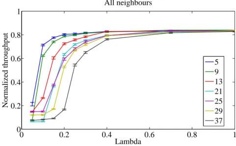
3.21 Normalized throughput for all neighbours . . . 79
3.22 Normalized throughput as a function ofλfor N=5 and N=9. . . . 80
3.23 Normalized throughput as a function ofλfor N=13 and N=21. . . . 80
3.24 Normalized throughput as a function ofλfor N=25 and N= 29. . . 80
3.25 Normalized throughput as a function ofλfor N=37. . . . 81
4.1 Interoperability scenario targeting WiFi and HSDPA. . . 88
4.2 Suitability profile. . . 89
4.3 Throughput in HSDPA with CRRM entity exploring the diversity gain for a ra-dius equal to 50 m, a) for load thresholds equal to 0.6, and b) for load thresholds equal to 0.7. . . 95
4.4 HSDPA throughput vs. number of users without CRRM entity. . . 96
4.5 Accumulated dropped sessions vs. users. . . 96
4.6 Throughput results vs. number of user for several values of the cell radius (with and without the use of localization information). . . 97
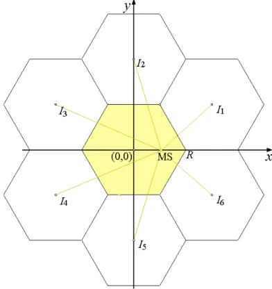
4.7 Scenario of common frequency pool [1]. . . 101
4.8 CRRM in the context of SA with two separated frequency bands. . . 102
4.9 Channel Quality measurements and MCS selection cycle. . . 104
4.10 Allocation matrix example over two frequency bands. . . 106
4.11 Example of an allocation matrix X for single-frequency single-code GMBS. . . 107
4.12 Simulation topology of the HSDPA networks. . . 108
4.13 From left to right, SINR as a function of the MS-BS distance for two cell radii (R∈ {300,1500} m) and PT x=1 dBW. . . 109
4.14 Interference received from neighbouring cells. . . 109
4.15 Average SINR [dB] as a function of the cell radius in meters. . . 110
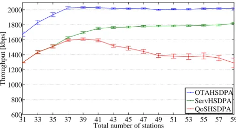
4.16 Average throughputs without the iCRRM. . . 112
4.17 Average service throughput with the iCRRM with normalized power. . . 113
4.18 Gain between the presence of and the iCRRM and just a CRRM as a function of the cell radius for 60 users. . . 113
4.19 Variation of the load with the number of stations for both frequency bands and R=300, 900 and 1500 m. . . 114
4.20 Exchanges between frequency bands for cell radius a) R=300, b) R=900 and c) R=1500 m . . . 114
4.21 CQI15 usage for a cell radius R=300, 900 and 1500 m. . . 115
4.22 PER variation for a cell radius a) R=300, b) R=900 and c) R1500 m. . . 115
4.23 Packets delivered in topology 1 with the Tournament selection (solid lines) and List selection (dashed lines) algorithms. . . 121
4.24 The scenario under study: users get access to services from a WiFi or an HSDPA connection, depending on which one is more suitable. . . 122
A.1 Different IFS. . . 136
A.2 Exponential increase of the CW . . . 138
A.3 NAV and RTS/CTS with fragmentation. . . 140
B.1 TXOPLimit. . . 142
D.1 Topologie forλ= 9.5805 ∙ 10−4andλ= 1.916 ∙ 10−3. . . 153
D.2 Topologie forλ= 3.832 ∙ 10−3andλ= 4.790 ∙ 10−3. . . 154
D.3 Topologie forλ= 7.665 ∙ 10−3and 8.622∙ 10−3. . . 154
D.4 Topologie forλ= 9.580 ∙ 10−3. . . 154
E.1 Throughput in HSDPA with CRRM entity exploring the diversity gain for a radius equal to 50 m, a) for load thresholds equal to 0.5 and b) for load thresholds equal to 0.8. . . 156
E.2 HSDPA throughput vs. number of users without CRRM entity, a) for radius=75m and b) for radius=100m. . . 157
F.1 Average power and interference [dBW] within a cell as a function of the inter-cell distance [m] with PT x1 dBW. . . 159
2.1 User priorities to access categories mappings . . . 12
2.2 EDCA default settings. . . 13
2.3 IEEE 802.11a PHY modes. . . 21
2.4 IEEE 802.11a OFDM PHY characteristics. . . 21
2.5 Actions of the events in the simulator . . . 24
2.6 IEEE 802.11a PHY modes. . . 42
2.7 Traffic parameters [2] . . . 43
3.1 MAC and PHY parameters. . . 53
3.2 Traffic parameters [2], and usage. . . 54
3.3 Traffic Parameters [2]. . . 63
3.4 Mapping ofρ, N, #C, #U. . . . 78
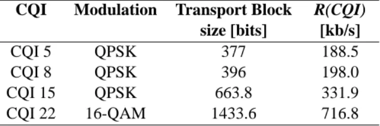
4.1 Transport block size and bit rate associated to CQI . . . 90
4.2 WiFi traffic parameters [2] . . . 92
4.3 WiFi MAC and PHY parameters . . . 92
4.4 HSDPA and WiFi simulation parameters. . . 93
4.5 Parameters and Models used for 2 and 5 GHz bands . . . 102
4.6 Transport block size and bit rate associated to CQI. . . 103
4.7 Values for the normalized transmitter power PT x,R0 [dBW], for the 2 and 5 GHz bands. . . 111
4.8 The relation between the SINR, modulation and data rate. . . 118
4.9 The setpoints in study. . . 119
4.10 Results for each cost function. . . 119
3GPP 3rd Generation Partnership Project
AC Access Category
ACK Acknowledgement
ACt Allocation Constraint
ACU Admission Control Unit
ADDBA Add Block ACK
AIFS Arbitration Interframe Space
AMC Adaptive Modulation and Coding
AoA Angle of Arrival
AP Access Point
ARF Automatic Rate Fallback
ARQ Automatic Repeat Request
AT Aggregated Throughput
B3G Beyond 3G
BA Block Acknowledgement
BC Bandwidth Constraint
BE Best Effort
BER Bit Error Rate
BFWA Broadband Fixed Wireless Access
BK Background
BRAN Broadband Radio Access Networks
BS Base Station
BSS Basic Service Set
CA Carrier Aggregation
CAP Controlled Access Phase
CF Contention Free
CFP Contention Free Period
CP Contention Period
CPC Cognitive Pilot Channel
CPICH Common Pilot Channel
CQI Channel Quality Indicator
CR Cognitive Radio
CRRM Common Radio Resource Management
CS Carrier Sense
CSI Channel State Information
CSMA Carrier Sense Multiple Access xxi
CSMA-CA Carrier Sense Multiple Access with Collision Avoidance
CTS Clear to Send
CW Contention Window
DCF Distribute Coordination Function
DELBA Delete Block Acknowledgement
DIFS DCF Interframe Space
DIFS Distributed Inter-Frame Space
DL Downlink
DS Distribution System
DSM Distribution System Medium
DVB-H Digital Video Broadcast - Handhelds
EDCA Enhanced Distributed Channel Access
EDCAF Enhanced Distributed Channel Access Function
EIFS Extended Interframe Space
ETSI European Telecommunications Standards Institute
FCC Federal Communications Commission
FCS Frame Check Sequence
FEC Forward Error Correction
GAP General Assignment Problem
GMBS General Multi-Band Scheduling
H-ARQ Hybrid Automatic Repeat Request
HC Hybrid Coordinator
HCCA HCF Controlled Channel Access
HCF Hybrid Coordination Function
HSDPA High Speed Downlink Packet Access
HS-DPCCS High-Speed Dedicated Physical Control Channel
HS-PDSCH High Speed Physical Downlink Shared Channel
HSUPA High Speed Uplink Packet Access
iCRRM Integrated CRRM
IFFT Inverse Fast Fourier Transform
IFS Interframe Space
IMT-A International Mobile Telecommunications-Advanced
IP Integer Programming
ISI Inter-Symbol Interference
LAN Local Area Network
LTE Long Term Evolution
MAC Medium Access Control
MBS Multi-Band Scheduling
MCS Modulation and Coding Scheme
MMPDU MAC Management Protocol Data Unit
MO-GAP Multiple Objectives GAP
MPDU MAC Protocol Data Unit
MS Mobile Station
MSDU MAC Service Data Unit
NAV Network Allocation Vector
nQSTA non QoS station
NRTV Near Real Time Video
OFDM Orthogonal Frequency Division Multiplexing
OSI Open Systems Interconnection
PC Point Coordinator
PCF Point Coordination Function
PER Packet Error Rate
PF Profit Function
PHY Physical Layer
PIFS Point Coordination Function (PCF) Interframe Space
PLCP Physical Layer Convergence Procedure
PPDU PLCP Protocol Data Unit
PSDU Physical layer Service Data Unit
QAP QoS AP
QBSS QoS Network BSS
QLRC QoS Long Retry Counter
QoE Quality of Experience
QoS Quality of Service
QSRC QoS Short Retry Counter
QSTA QoS STA
RA Resource Allocation
RAN Radio Access Network
RAT Radio Access Technology
RNC Radio Network Controller
RR Round Robin
RRM Radio Resource Management
RSS Received Signal Strength
SA Spectrum Aggregation
SDR Software-defined Radio
SIFS Short Interframe Space
SIFS Short Inter-Frame Space
SINR Signal to Interference-plus-Noise Ratio
SIR Signal-to-Interference Ratio
SO-GAP Single Objective General Assignment Problem
STA Station
TC Traffic Category
TDoA Time Difference of Arrival
TID Traffic Identifier
ToA Time of Arrival
TS Traffic Stream
TTI Time Transmission Interval
TXOP Transmission Opportunities
UMTS Universal Mobile Telecommunication Systems
UP User Priorities
VI Video
VO Voice
WCDMA Wideband Code Division Multiple Access
WiMAX World Wide Interoperability for Microwave Access
WLAN Wireless Local Area Network
Introduction
1.1
Motivation
The fast development and deployment of multimedia wireless and mobile communication sys-tems Beyond 3G (B3G) is mainly driven by the demand of multimedia traffic, and research on network design and multi-service traffic aspects is strategic. Furthermore, heterogeneous mobile and wireless networks are nowadays available in the market, with very different characteristics, and dimensioning approaches. The research community is now directing its interest towards new ways of optimising not only each system individually, through cross-layer design in the context of All-IP networks but also of achieving cross-system optimization, making the simultaneous use of systems with totally different access technologies transparent to the user. Innovative ar-chitectures and protocols are being proposed for this coexistence, and mechanisms to guarantee the Quality of Service (QoS) will be explored, including Medium Access Control (MAC) layer solutions. Since there are totally different protocols and requirements in each system, a har-monized solution is sought. Aspects of intersystem handover, dynamic resource allocation and dynamic spectrum use are going to be addressed. The QoS provision for each service (within different traffic classes), and, based on adequate characterisation parameters, the identification of suitable schemes and network planning methodologies to guarantee high capacity (in several scenarios) are of particular interest in this thesis. One of the main ideas to be explored is related with the need for cooperation among physical, MAC, network and transport layers; the way that this can be done and the new definitions of cross-layer protocols are therefore important areas for study and investigation.
FIGURE1.1: Example of interoperability among WiMAX, WiFi and B3G.
The coexistence scenario across heterogeneous networks should be seen by the end user as the ability to attain a plethora of multimedia services under a single platform in a ubiquitous and transparent fashion, providing the impetus for system solutions addressing network discovery, selection, connection, and reselection as the terminal equipment migrates between collocated networks.
In the scope of this thesis, interoperability among B3G and IEEE 802.11 is investigated, since these technologies, together with IEEE 802.16 and Long Term Evolution, as shown in Figure 1.1, are widely seen as the enablers for converging the wireless and mobile worlds. By using the existing simulation platforms for different systems such as High Speed Downlink Packet Access (HSDPA) and WiFi, a common Radio Resource Management (RRM) module has been developed in order to provide a step toward network convergence to hide the heterogeneity between operators and technologies.
1.2
Objectives
This work aims at implementing HSDPA and IEEE 802.11e evaluation tools for evaluating RRM protocol performance. Furthermore, cross-layer scheduling and link adaptation provide key output to enhance the effective capacity and coverage in a more cost-effective way. The IEEE 802.11 (also known as WiFi) technology has seen high penetration in the Broadband Fixed Wireless Access (BFWA) market to provide data services to hotspot areas, mainly due to ease of network deployment and low cost. However, with the QoS constraints becoming evermore stringent, the IEEE opted to evolve the 802.11 standard to 802.11e, a WiFi technology
for QoS support. The key enhancement in this evolved standard can be found in the MAC layer, which now provides support for differentiated service classes and proposes techniques to enhance the ability of the Physical Layer (PHY) to deliver time-critical multimedia traffic. This work addresses innovative enhancement to IEEE 802.11e by pursuing research studies on the application of cross-layer signaling to improve QoS delivery, and provide more efficient usage of radio resources by adapting such parameters as arbitrary interframe spacing, a differentiated backoff procedure, and transmission opportunities, as well as acknowledgment policies. A key output from this work is also the development of an event-driven PHY/MAC layer simulator for IEEE 802.11e.
Radio Access Technology (RAT) selection algorithms have been studied in the literature, and nowadays equipment with several RATs incorporated is already common. One needs to deter-mine the gains obtained by using WiFi as a backup network for HSDPA have been obtained. The coexistence of the two standards allows prevention of QoS deterioration when in a low mobility scenario. The proposed RAT selection algorithm is based on the load of each system, and the re-search seeks the gain on supported network load with the implementation of this QoS procedure over the HSDPA-alone system whilst considering positioning. As a consequence, when there is heavy load on the IEEE 802.11e network, acceptance of high-priority services will affect the delay in low-priority services like FTP.
Supporting additional system capacity and higher data rates through high speed RAT, such as the International Mobile Telecommunications-Advanced (IMT-A), users can be granted univer-sal access to broadband services. One important enabling factor is the availability of bandwidth, which is also related to the assignment of frequency spectrum bands for IMT-A different tech-nologies. This is impeded by the existing highly fragmented radio frequency spectrum that does not match the actual demand for transmission and network resources. Such fragmentation poses a challenge during dynamic spectrum use where multiple frequency bands can be assigned in support of the users and the mobile transmission system’s ability to support a wide range of services across all elements of the network (i.e., core, distribution and access [1]).
The fragmented available spectrum can be virtually joined through the Spectrum Aggregation (SA) technique suggested by IMT-A and Long Term Evolution-Advanced (LTE-A) [3], [4], [5]. Information about how to aggregate contiguous and not contiguous parts of the highly fragmented spectrum to be used and how to allocate users over the dedicated and shared bands
of an operator, can improve the overall system capacity, through the integration of spectrum and network resource management functionalities.
1.3
Contributions
A substantial part of the work presented in this thesis followed the steps of the IST-UNITE European project in which scenarios were created, cross layer optimization for several RATs was proposed, protocols and mechanisms that allow for the interoperability of the same RATs were proposed.
This thesis has several original contributions on Optimization of the Interoperability and Dy-namic Spectrum Management in Mobile Communications Systems Beyond 3G that have al-ready been reflected in the work developed in the framework of the IST-UNITE project [6], [7] and CROSSNET project [8] and in papers published, accepted for publication or submitted to evaluation both in conferences and journals:
• After developing the IEEE 802.11e simulator, this work on event-driven simulation for
IEEE 802.11e optimization was published in [9];
• The IEEE 802.11e standard specifies acknowledgement policies but it leaves the size of
the buffer that implements this procedure open. The research of the impact of the buffer size on the implementation of IEEE 802.11e block acknowledgement policies was pub-lished in [10], [11];
• Two functions that provide the IEEE 802.11e Enhanced Distributed Channel Access (EDCA)
Arbitration Interframe Space (AIFS) and the contention window limits in a dynamic man-ner are proposed in [12], trough a cross-layer design of a weighted scheduler algorithm;
• Research work was done on routing for ad hoc networks with the work colleague Joao
Ferro [13], [14]. The channel conditions and link layer information of each station are used in determining the best possible path with the IEEE 802.11e cross-layer multi-hop simulator that incorporates network layer components;
• Cognitive radio in the scope of ad hoc networks was addressed in [15]. A network of
hierarchically bonded with user access to a flexible wireless ad hoc IEEE 802.11e network is considered;
• Common Radio Resource Management (CRRM) interoperability between HSDPA and
IEEE 802.11e was also addressed. A suitability function for the RAT selection was pro-posed and evaluated [16], [17]. In [18], the impact of positioning in the performance of RAT selection with the load suitability function was studied;
• In the scope of CRRM, besides managing several Radio Access Technologies, SA, a new
new procedure proposed in Long Term Evolution (LTE), was also explored, in which sev-eral bunch of spectrum bands are managed. An Integrated CRRM (iCRRM) was proposed in [19] that facilitates the management of several spectrum bands.
1.4
Organization
The outline of this thesis is described in what follows.
Besides introduction, the thesis has more four Chapters, and six Appendices. Chapter 2 has two parts. The first part introduces the main aspects that characterize the IEEE 802.11e standard (Section 2.1 to 2.5). The second part presents the main aspects of the developed IEEE 802.11e simulator, as well as performance results (section 2.6 and 2.7 ). Finally conclusions are drawn in section 2.8, where proposal for future work are also discussed.
Chapter 3 presents the optimization of IEEE 802.11e. It is divided into three parts: Section 3.2 addresses the optimization of the BA procedure, while Section 3.3 addresses the optimization through cross-layer design. Section 3.4 presents an analytical formulation for a multi-hop ad hoc network. The first part starts by presenting the BA procedure followed by a review of the state of the art on BA. Then, the system scenario and assumptions in which tests were performed are addressed and finally a summary and conclusions regarding the BA studies are presented. The second part of the chapter starts by presenting the state of the art on optimization procedures for IEEE 802.11 and on the interoperability among wireless systems, then it are described the assumptions for system and scenarios, including details on traffic parameters, followed by the description of the developed cross-layer algorithm. Then, a comparison of simulation results between the presence and absence of the proposed weighted cross-layer design algorithm is performed. Very promising results are obtained by using the MAC plus PHY layers simulator.
Finally, conclusions are drawn as well as suggestions for future work. The third part of this Chapter presents the notation and formulation, followed by the network and model scope, then some numerical results and in the end, a summary and conclusions.
Chapter 4 is divided into three Sections that consider CRRMs in different perspectives. In the first Section, the CRRM has the capacity to schedule users in completely different RATs: one is centralized, HSDPA, whilst the other is distributed, WiFi. The interworking scenario is pro-posed, and the positioning based suitability policy is described, in terms of the RAT selection procedures and of the identification of suitable metrics for normalized load whilst WiFi and HSDPA. The numerical results accounting for localization in RAT selection are then addressed. Finally, the conclusions are drawn. In the second Section, one addresses a CRRM that is capa-ble of scheduling users in different bands within the same RAT. First, the objective of the work and system model are presented, followed by the General Multi-Band Scheduling (GMBS) as a General Assignment Problem (GAP). Then, a formulation to obtain the average Signal to Interference-plus-Noise Ratio (SINR), with unitary reuse pattern is proposed and its dependence on the cell coverage distance is analyzed. Finally, the SA results with the proposed iCRRM are discussed, and conclusions are drawn. In this chapter it is also proposed a scenario for interop-erability between HSDPA and WiFi in which the end-user is travelling in public transportation system and requesting multimedia services to the operator. It was sought the most efficient way to manage routing packets inside the WiFi ad hoc network. Finally, the challenges that need to be addressed in order to materialize the envisaged cognitive radio scenario in public transportation are discussed.
Finally Chapter 5 presents the conclusions, some final considerations and suggestions for future research.
IEEE 802.11e Event Driven Simulation
In recent years, an amazingly rapid evolution in Wireless Local Area Network (WLAN) as occurred. Due to the low cost, and easiness of deployment, IEEE 802.11 WLANs have been used so widely that they become the dominant WLAN technology. This is mainly because the technology is reaching an unprecedented maturity in regard to providing higher bit rates as the time goes by; however, it could not fulfil the increasing demand for QoS support from the increasingly popular multimedia applications yet.
To overcome this limitation, the IEEE 802.11e standard [20] is specified aiming to support QoS by providing differentiated classes of service in the MAC layer and to enhance the ability of the physical layer so that they can deliver time-critical multimedia traffic, in addition to traditional data packets.
A C++ simulator was developed that enables simulations that analyse the performance and al-lows the improvement of IEEE 802.11e mechanisms, such as optimization of arbitrary inter frame spacing, differentiated backoff procedure, and the transmission opportunities for each service class, as well as experiments on acknowledgment policies.
This chapter is organized into two parts. The first part introduces the main aspects that charac-terize the IEEE 802.11e standard (Section 2.1 to 2.5). The second part presents the main aspects of the developed IEEE 802.11e simulator, as well as performance results (section 2.6 and 2.7 ). Finally conclusions are drawn in section 2.8, where proposal for future work are also discussed. Complete details on the Distributed Coordination Function are addressed in Appendix A, while Appendix B gives a detailed overview of the Hybrid Coordination Function.
FIGURE2.1: Architecture for IEEE 802.11e.
2.1
IEEE 802.11e general aspects
The IEEE 802.11 architecture consists of several components that interact to provide a WLAN that supports station mobility transparently to upper layers. The Basic Service Set (BSS) is the basic building block of an IEEE 802.11 Local Area Network (LAN). Figure 2.1 shows two BSSs, each of which have two stations that are members of the BSS. It is useful to think of the ovals used to depict a BSS as the coverage area within which the member stations of the BSS may remain in good quality communication. If a station moves out of its BSS it can no longer directly communicate with other members of the BSS. PHY limitations determine the direct station-to-station distance that may be supported. For some networks this distance is sufficient; for other networks, increased coverage is required. Instead of existing independently, a BSS may also form a component of an extended form of network that is built with multiple BSSs. The architectural component used to interconnect BSSs is the Distribution System (DS). IEEE 802.11 logically separates the Wireless Medium (WM) from the Distribution System Medium (DSM). Each logical medium is used for different purposes, by a different component of the architecture.
The DS enables mobile device support by providing the logical services necessary to handle address to destination mapping and seamless integration of multiple BSSs. An Access Point (AP) is a Station (STA) that provides access to the DS by providing DS services in addition to acting as a STA Data move between a BSS and the DS via an AP. All APs are also STAs; thus they are addressable entities. The addresses used by an AP for communication on the WM and on the DSM are not necessarily the same.
All data from non-IEEE 802.11 LANs enter the IEEE 802.11 architecture via a portal. The gateway provides logical integration between the IEEE 802.11 architecture and existing wired LANs. It is possible for one device to offer both the functions of an AP and a gateway.
For wireless PHYs, well-defined coverage areas simply do not exist. Propagation characteristics are dynamic and unpredictable, a small change in position or direction may result in dramatic
differences in signal strength. Whether a STA is stationary or mobile similar effects occur . The IEEE 802.11e QoS facility provides MAC enhancements to support LAN applications with QoS requirements. The QoS enhancements are available to QoS STA (QSTA) associated with a QoS AP (QAP) in a QoS Network BSS (QBSS). This amendment provides two mechanisms for the support of applications with QoS requirements, the EDCA and the HCF Controlled Channel Access (HCCA) used to support applications with QoS requirements. To handle QoS traffic in a manner comparable to other IEEE 802.11 LANs, the IEEE 802.11 QoS facility requires the IEEE 802.11 MAC sublayers to incorporate functionalities that are not traditional.
The first mechanism, called the EDCA, delivers traffic based on differentiating User Prioritiess (UPs). This differentiation is achieved by varying the following for different UP values:
• amount of time a STA senses the channel to be idle before backoff or transmission; • length of the contention window to be used for the backoff;
• duration a STA may transmit after it acquires the channel.
The second mechanism, called HCCA, allows for the reservation of Transmission Opportunitiess (TXOPs) with the HC. A non–AP QSTA based on its requirements requests o an entity called Hybrid Coordinator (HC) for a TXOPs, both for its own transmissions as well as for transmis-sions from the QAP to itself.
2.2
Main concepts MAC sublayer functions
The enhanced MAC architecture of WiFi with QoS support can be described as presented in Figure 2.2. PCF and Hybrid Coordination Function (HCF) are provided through the services of the Distribute Coordination Function (DCF). In a non QoS station (nQSTA) the HCF is not present, it is the basic model of a STA in the WM. In a QSTA implementation, both DCF and HCF are present. PCF is optional in all STAs.
2.2.1 Distribute Coordination Function
The fundamental access method of the IEEE 802.11 MAC is a DCF known as Carrier Sense Multiple Access with Collision Avoidance (CSMA-CA). The DCF shall be implemented in all
FIGURE2.2: Medium access control architecture.
STAs, for use within both independent BSS and infrastructure network configurations. For a STA to transmit, it shall sense the medium to determine if another STA is transmitting. If the medium is not determined to be busy, the transmission may proceed. The CSMA-CA distributed algorithm mandates that a gap of a minimum specified duration exist between contiguous frame sequences. A transmitting STA shall ensure that the medium is idle for this required duration before attempting to transmit. If the medium is determined to be busy, the STA shall defer until the end of the current transmission. After deferral, or prior to attempting to transmit again imme-diately after a successful transmission, the STA shall select a random backoff interval and shall decrement the backoff interval counter while the medium is idle. A more complete overview of DCF is presented Appendix A, including the carrier sense mechanism, the interframe spacing, the random backoff timer and the backoff procedure, setting and resetting the network allocation vector, the usage of RTS/CTS with fragmentation.
2.2.2 Point Coordination Function
The IEEE 802.11 MAC layer may also incorporate an optional access method called a PCF, which is only usable on infrastructure network configurations. This access method uses a Point Coordinator (PC), which shall operate at the access point of the BSS, to determine which STA currently has the right to transmit. The operation is essentially that of polling, with the PC performing the role of the polling master. The operation of the PCF may require additional coordination, not specified in the IEEE 802.11 standard, to permit efficient operation in cases where multiple point-coordinated BSSs are operating on the same channel, in overlapping phys-ical space.
The PCF uses a virtual Carrier Sense (CS) mechanism aided by an access priority mechanism. The PCF shall distribute information within beacon management frames to gain control of the medium by setting the Network Allocation Vector (NAV) in STAs. In addition, all frame trans-missions under the PCF may use an Interframe Space (IFS) that is smaller than the Distributed Inter-Frame Space (DIFS) for frames transmitted via the DCF. The use of a smaller IFS implies that point-coordinated traffic shall have priority access to the medium over STAs in overlap-ping BSSs operating under the DCF access method. The access priority provided by a PCF may be utilized to create a Contention Free (CF) access method. The PC controls the frame transmissions of the STAs so as to eliminate contention for a limited period of time.
2.2.3 Hybrid Coordination Function
The QoS enhancement added by IEEE 802.11e amendment includes an additional coordination function called HCF that is only usable in a QoS network with QBSS configurations. The HCF shall be implemented in all QSTAs. The HCF combines functions from the DCF and PCF with some enhanced QoS-specific mechanisms and frame subtypes to allow a uniform set of frame exchange sequences to be used for QoS data transfers during both the Contention Period (CP) and Contention Free Period (CFP). The HCF uses both a contention-based channel access method, called the EDCA mechanism for contention-based transfer and a controlled channel access, referred to as the HCCA mechanism, for contention-free transfer. Appendix B provides a detailed overview of the Hybrid Coordination Function.
2.2.3.1 Enhanced Distributed Channel Access
The EDCA mechanism provides differentiated, distributed access to the WM for QSTAs using eight different UPs. The EDCA mechanism defines four Access Category (AC) that provide support for the delivery of traffic with UPs at the QSTAs. The AC is derived from the UPs as presented in Table 2.1. The mapping between UPs and ACs is described in Figure 2.3.
For each AC, an enhanced variant of the DCF, called an Enhanced Distributed Channel Access Function (EDCAF), contends for TXOPs using a set of EDCA parameters from the EDCA Parameter Set element or from the default values for the parameters when no EDCA Parameter Set element is received from the QAP of the QBSS with which the QSTA is associated, where:
FIGURE2.3: The access categories in EDCA. TABLE2.1: User priorities to access categories mappings
Priority UP (Same as 802.1D AC Designation
802.1D user priority) Designation
Lowest 1 BK AC_BK Background
↓
2 — AC_BK Background
0 BE AC_BE Best Effort
3 EE AC_BE Best Effort
4 CL AC_VI Video
5 VI AC_VI Video
6 VO AC_VO Voice
Highest 7 NC AC_VO Voice
1. The parameters used by the EDCAF to control its operation are defined by the MIB at-tribute table dot11QAPEDCATable [20] at the QAP and by MIB atat-tribute table dot11-EDCATable [20] at the non-AP QSTA.
2. The minimum specified idle duration time is not the constant value DIFS as defined for DCF, but is a distinct value (contained in the MIB attribute table dot11QAPEDCATable-AIFSN [20] for a QAP and in the MIB table dot11EDCATabledot11QAPEDCATable-AIFSN [20] for a non-AP QSTA) assigned either by a management entity or by a QAP.
3. The contention window minimum and maximum limits, aCW min and aCW min, respec-tively, from which the random backoff is computed, are not fixed per PHY, as with DCF, but are variable (contained in the MIB attribute tables dot11QAPEDCACWmin and
TABLE2.2: EDCA default settings.
Access Category CWmin CWmax AIFS
AC_BK aCWmin (7) aCWmax (255) SIFS + 7*TS
AC_BE aCWmin (7) aCWmax (255) SIFS + 3*TS
AC_VI (aCWmin+1)/2-1 aCWmin (7) SIFS + 2*TS AC_VO (aCWmin+1)/4-1 (aCWmin+1)/2-1 SIFS + 2*TS
dot11QAPEDCACWmax for a QAP and in the MIB attribute tables dot11EDCATable-CWmin and dot11EDCATableCWmax for a non-AP QSTA) and assigned by a manage-ment entity or by a QAP, as presented in Table 2.2.
4. Collisions between contending EDCAFs within a QSTA are resolved within the QSTA so that the data frames from the higher priority AC receives the TXOP and the data frames from the lower priority colliding ACs behave as if there were an external collision on the WM. However, this collision behavior does not include setting retry bits in the MAC headers of MAC Protocol Data Units (MPDUs) at the head of the lower priority ACs, as would be done after a transmission attempt that was unsuccessful due to an actual external collision on the WM.
5. During an EDCA TXOP won by an EDCAF, a QSTA may initiate multiple frame ex-change sequences to transmit MAC Management Protocol Data Units (MMPDUs) and/or MAC Service Data Units (MSDUs) within the same AC. The duration of this EDCA TXOP is bounded, for an AC, by the value in dot11QAPEDCATXOPLimit MIB variable for a QAP and in dot11EDCATableTXOPLimit MIB table for a non-AP QSTA.
The management frames shall be sent using the access category AC_VO without being restricted by admission control procedures. A QSTA shall also send management frames using the access category AC_VO before associating with any BSS, even if there is no QoS facility available in that BSS.
A more complete overview of HCF is given in Appendix B, which includes details on EDCA TXOP, obtaining an EDCA TXOP, multiple frame transmission in an EDCA TXOP, and the EDCA backoff procedure.
2.2.3.2 HCF Controlled Channel Access
The HCCA mechanism uses a QoS-aware centralized coordinator, called a HC, and operates under rules that are different from the PC of the PCF. The HC is collocated with the QAP of the QBSS and uses the HC’s higher priority of access to the WM to initiate frame exchange sequences and to allocate TXOPs to itself and other QSTAs in order to provide limited-duration Controlled Access Phase (CAP) for CF transfer of QoS data.
The HC traffic delivery and TXOP allocation may be scheduled during the CP and any locally generated CFP (generated optionally by the HC) to meet the QoS requirements of a particular Traffic Category (TC) or Traffic Stream (TS). TXOP allocations and contention-free transfers of QoS traffic can be based on the HC’s QBSS-wide knowledge of the amounts of pending traffic belonging to different TS and/or TCs and are subject to QBSS-specific QoS policies. The HCF protects the transmissions during each CAP using the virtual CS mechanism.
2.2.4 Coexistence of DCF, PCF, and HCF
The DCF and the centralized coordination function (either PCF or HCF) shall coexist in a man-ner that permits both to operate concurrently within the same BSS. When a PC is operating in a BSS, the PCF and DCF access methods alternate, with a CFP followed by a CP.
When an HC is operating in a QBSS, it may generate an alternation of CFP and CP in the same way as a PC, using the DCF access method only during the CP. The HCF access methods (controlled and contention-based) operate sequentially when the channel is in CP. Sequential operation allows the polled and contention-based access methods to alternate, within intervals as short as the time to transmit a frame exchange sequence.
2.2.5 Overview of fragmentation/defragmentation
The process of partitioning a MAC Service Data Unit (MSDU) or a MAC Management Pro-tocol Data Unit (MMPDU) into smaller MAC level frames, MPDUs, is called fragmentation. Fragmentation creates MPDUs smaller than the original MSDU or MMPDU length to increase reliability, by increasing the probability of successful transmission of the MSDU or MMPDU in cases where channel characteristics limit reception reliability for longer frames, as shown in Figure 2.4. QSTAs may use fragmentation to use the medium efficiently in consideration of
FIGURE2.4: Fragmentation.
the duration available in granted TXOPs. Fragmentation is accomplished at each immediate transmitter. The process of recombining MPDUs into a single MSDU or MMPDU is defined as defragmentation. Defragmentation is accomplished at each immediate recipient.
Only MPDUs with a unicast receiver address shall be fragmented. Broadcast/multicast frames shall not be fragmented even if their length exceeds adot11FragmentationThreshold.
The MPDUs resulting from the fragmentation of an MSDU or MMPDU are sent as independent transmissions, each of which is separately acknowledged. This permits transmission retries to occur per fragment, rather than per MSDU or MMPDU. Unless interrupted due to medium occupancy limitations for a given PHY or TXOP limitations for QSTA, the fragments of a single MSDU or MMPDU are sent as a burst during the CP, using a single invocation of the DCF or EDCA medium access procedure. The fragments of a single MSDU or MMPDU are either:
• Sent during a CFP as individual frames obeying the rules of the PC medium access
pro-cedure or
• Sent as a burst in an EDCA or HCCA TXOP.
2.3
Block Acknowledgment
The Block Acknowledgement (BA) mechanism improves channel efficiency by aggregating sev-eral acknowledgments into one frame. There are two types of Block ACK mechanisms: imme-diate and delayed. Immeimme-diate Block ACK is suitable for high-bandwidth, low-latency traffic while the delayed Block ACK is suitable for applications that tolerate moderate latency. The QSTA with data to send using the Block ACK mechanism is referred to as the originator, and the receiver of that data as the recipient.
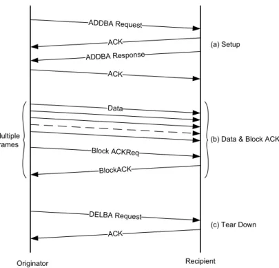
The Block ACK mechanism is initialized by an exchange of Add Block ACK (ADDBA) Re-quest/Response frames. After initialization, blocks of QoS data frames can be transmitted from
FIGURE2.5: Block ACK sequence.
the originator to the recipient. A block may be started within a polled TXOP or by winning EDCA contention. The number of frames in the block is limited, and the amount of state that is to be kept by the recipient is bounded. The MPDUs within the block of frames are acknowledged by a BlockAck control frame, which is requested by a BlockAckReq control frame.
Figure 2.5 illustrates the message sequence chart for the setup, data and Block ACK transfer, and the teardown of the Block ACK mechanism.
2.3.1 Setup and modification of the Block ACK parameters
A QSTA that intends to use the Block ACK mechanism for the transmission of QoS data frames to a peer should first check whether the intended peer QSTA is capable of participating in Block ACK mechanism by discovering and examining its buffer of Block ACK. If the intended peer QSTA is capable of participating, the originator sends an ADDBA Request frame indicating the Traffic Identifier (TID) for which the Block ACK is being set up. The Block ACK Policy and Buffer Size fields in the ADDBA Request frame are advisory and may be changed by the recipient. The receiving QSTA responds by an ADDBA Response frame. The receiving QSTA, which is the intended peer, has the option of accepting or rejecting the request. When the QSTA accepts, then a Block ACK agreement exists between the originator and recipient. When the
QSTA accepts, it indicates the type of Block ACK and the number of buffers that it allocates for the support of this block. If the receiving QSTA rejects the request, then the originator shall not use the Block ACK mechanism.
Once the Block ACK exchange has been set up, data and ACK frames are transferred using the procedure described in the next section.
2.3.2 Data and ACK transfer
After setting up for the Block exchange following the procedure in previous section, the origina-tor may transmit a block of QoS data frames separated by SIFS period, with the total number of frames not exceeding the Buffer Size subfield value in the associated ADDBA Response frame. Each of the frames have the ACK Policy subfield in the QoS Control field set to Block ACK. The RA field of the frames is be the recipient’s unicast address. The originator requests acknowl-edgment of outstanding QoS data frames by sending a BlockAckReq frame. The recipient has to maintain a Block ACK record for the block.
Subject to any constraints in this subclause about permitted use of TXOP according to the chan-nel access mechanism used, the originator may:
• Separate the Block and BlockAckReq frames into separate TXOPs; • Split a Block frame across multiple TXOPs;
• Sequence or interleave MPDUs for different RAs within a TXOP.
A protective mechanism (such as transmitting using Request to Send (RTS)/Clear to Send (CTS)) should be used to reduce the probability of other STAs transmitting during the TXOP. If no protective mechanism is used, then the first frame that is sent as a block has a response frame and has the Duration field set so that the NAVs are set to appropriate values at all STAs in the QBSS.
The originator uses the Block ACK starting sequence control to signal the first MPDU in the block for which an acknowledgment is expected. MPDUs in the recipient’s buffer with a se-quence control value that any complete MSDUs from buffered preceding MPDUs and indicate these to its higher layer. The recipient then releases any buffers held by preceding MPDUs.
FIGURE2.6: Immediate Block ACK.
The range of the outstanding MPDUs (i.e., the reorder buffer) begins on an MSDU boundary. The total number of frames that can be sent depends on the total number of MPDUs in all the outstanding MSDUs. The total number of MPDUs in these MSDUs may not exceed the reorder buffer size in the receiver.
The recipient maintains a Block ACK record consisting of originator address, TID, and a record of reordering buffer size indexed by the received MPDU sequence control value. This record holds the acknowledgment state of the data frames received from the originator.
If the immediate Block ACK policy is used, the recipient responds to a BlockAckReq frame with a Block ACK frame. If the recipient sends the Block ACK frame, the originator updates its own record and retries any frames that are not acknowledged in the Block ACK frame, either in another block or individually. If the delayed Block ACK policy is used, the recipient responds to a BlockAckReq frame with an ACK frame. The recipient then sends its Block ACK response in a subsequently obtained TXOP. Once the contents of the Block ACK frame have been prepared, the recipient sends this frame in the earliest possible TXOP using the highest priority AC. The originator responds with an ACK frame upon receipt of the Block ACK frame.
The Block ACK frame contains acknowledgments for the previous MPDUs. In the Block-ACK frame, the QSTA acknowledges only the MPDUs starting from the starting sequence MPDU until the last MPDU that has been received, and the QSTA sets bits in the Block ACK bitmap corresponding to all other MPDUs to 0. If the BlockAck frame indicates that an MPDU was not received correctly, the originator retries that MPDU subject to that MPDU’s appropriate lifetime limit. A typical Block ACK frame exchange sequence using the immediate Block ACK is pre-sented in Figure 2.6. A typical Block ACK sequence using the delayed Block ACK is prepre-sented
FIGURE2.7: Delayed Block ACK.
in Figure 2.7. The subsequent Block ACK request starting sequence number is higher than or equal to the starting sequence number of the immediately preceding BlockAckReq frame. The originator may continue to transmit MPDUs to the recipient after transmitting the Block-AckReq frame, but before receiving the Block ACK frame (applicable only to delayed Block ACK). The bitmap in the Block ACK frame includes the status of frames received between the start sequence number and the transmission of the BlockAckReq frame. A recipient sending a delayed Block ACK frame may update the bitmap with information on QoS data frames re-ceived between the receipt of the BlockAckReq frame and the transmission of the Block ACK frame.
If there is no response (i.e., neither a Block ACK nor an ACK frame) to the BlockAckReq frame, the originator may retransmit the BlockAckReq frame within the current TXOP (if time permits) or within a subsequent TXOP. MSDUs that are sent using the Block ACK mechanism are not subject to retry limits but only to MSDU lifetime. The originator need not set the retry bit for any possible retransmissions of the MPDUs.
The BlockAckReq frame is discarded if all MSDUs referenced by this BlockAckReq frame have been discarded from the transmit buffer due to expiry of their lifetime limit. In order to improve efficiency, originators using the Block ACK facility may send MPDU frames with the ACK Policy subfield in QoS control frames set to Normal ACK if only a few MPDUs are available for transmission. The Block ACK record is updated irrespective of the ACK Policy subfield in the QoS data frame for the TID with an active Block ACK. When there is sufficient number of MPDUs, the originator may switch back to the use of Block ACK. The reception of QoS data frames using Normal ACK policy are not used by the recipient to reset the timer to detect Block ACK timeout. This allows the recipient to delete the Block ACK if the originator does not switch back to using Block ACK.
2.3.3 Receive buffer operation
Upon the reception of a QoS data frame from the originator for which the Block ACK agreement exists, the recipient shall buffer the MSDU regardless of the value of the ACK Policy subfield within the QoS Control field of the QoS data frame. The recipient always indicates the reception of MSDU to its MAC client in order of increasing sequence number.
2.3.4 Teardown of the Block ACK mechanism
When the originator has no data to send and the final Block ACK exchange has completed, it sig-nals the end of its use of the Block ACK mechanism by sending the Delete Block Acknowledgement (DELBA) frame to its recipient. There is no management response frame from the recipient. The recipient of the DELBA frame releases all resources allocated for the Block ACK transfer. The Block ACK agreement may be torn down if there are no Block ACK, BlockAckReq, or QoS data frames (sent under Block ACK policy) for the Block ACK’s TID received from the peer within a duration of Block ACK timeout value.
2.4
IEEE 802.11a Physical and Link Layer
The IEEE 802.11a standard [2] [21] defines an Orthogonal Frequency Division Multiplexing (OFDM)-based PHY that operates in the 5 GHz frequency bands, being able to achieve bit-rates as high as 54 Mb/s. It defines 8 non-overlapping channels of 20 MHz each across the low and middle 5 GHz bands (5.15-5.35 GHz) and 4 more channels across the high 5 GHz band (5.725-5.825 GHz). Each of these channels is divided into 52 subcarriers, with each subcarrier being approximately 300 kHz wide. In each channel 48 subcarriers are used for data transmission, while the remaining four subcarriers are used as pilots for coherent detection. A high data rate is achieved by combining 48 lower bit-rate data streams transmitted in parallel, each modulating a different subcarrier. The parallel transmission of 52 modulation symbols, one in each subcar-rier, forms an OFDM symbol. These OFDM symbols are created by an Inverse Fast Fourier Transform (IFFT), which combines the subcarriers before transmission.
TABLE2.3: IEEE 802.11a PHY modes.
Mode Modulation Code Rate Bit-rate BpS
1 BPSK 1/2 6 Mb/s 3 2 BPSK 3/4 9 Mb/s 4.5 3 QPSK 1/2 12 Mb/s 6 4 QPSK 3/4 18 Mb/s 9 5 16-QAM 1/2 24 Mb/s 12 6 16-QAM 3/4 36 Mb/s 18 7 64-QAM 2/3 48 Mb/s 24 8 64-QAM 3/4 54 Mb/s 27
TABLE2.4: IEEE 802.11a OFDM PHY characteristics.
Characteristics Value Comments
aSlotTime 9 μs slot time
aSIFSTime 16 μs SIFS time
aDIFSTime 34 μs aDIFSTime= aSIFSTime + 2aSlotTime
aCWmin 15 min contention window size in unit of aSlotTime
aCWmax 1023 max contention window size in unit of aSlotTime
IEEE 802.11a specifies 8 different transmission modes, obtained with different combinations of modulation and convolutional code rate. Each transmission mode corresponds to a different bit-rate. Within an OFDM symbol the same transmission mode is used in all data subcarriers. The IEEE 802.11a transmission modes are listed in Table 2.3, together with the respective number of bytes transmitted in one OFDM symbol (Bytes-per-Symbol, BpS), and the IEEE 802.11a OFDM PHY characteristics in Table 2.4. The convolutional encoder always encodes data with code rate 1/2. The 3/4 and 2/3 codes are derived from the original 1/2 code by a technique called puncturing. Puncturing is a procedure for omitting some of the encoded bits in the transmitter, and inserting a dummy “zero” metric into the convolutional decoder at the receiver, in place of the omitted bits. This technique is a simpler and more efficient way of generating a higher code rate.
Within indoor radio environments, signals coming from multiple indirect paths added to the direct path induce delay spread. This may be large enough to cause Inter-Symbol Interference (ISI) if high rates are used. In OFDM counters this effectis opposed within each subcarrier by transmitting data in parallel using lower-rate subcarriers. However, ISI can be further reduced with the introduction of a guard interval in the beginning of each OFDM symbol. A guard interval longer than the maximum channel excess delay ensures that ISI is eliminated. With a guard interval of length Tg, a new block duration is obtained as Tb0= Tg+ Tb. In IEEE 802.11a, Tg=Tb/4=800 ns, which means that T’b=4 ns.
FIGURE2.8: Format of the IEEE 802.11a PPDU.
The cyclic prefix has two drawbacks worth to be mentioned. One of them is the overhead transmitted over the radio channel, which reduces the maximum data rate achievable on top of OFDM. The other one is that the cyclic prefix of duration Tgleads to a power loss, as the receiver only uses the energy received during time Tb, discarding the energy that corresponds to Tg. A power lossαgmust thus be taken into account:
αg= Tb
Tb0 (2.1)
Consequently, the ratio between the effective average symbol energy and the noise power spec-tral density, Eav/No, is related to the SINR in the following way:
Eav No =αg∙ Es No =αg∙ SINR (2.2)
where Es/N0is the ratio between the raw average symbol energy (i.e., including the energy of
the cyclic prefix) and the noise power spectral density (see Annex F).
The PLCP Protocol Data Unit (PPDU) frame format is depicted in Figure 2.8. It consists of a Physical Layer Convergence Procedure (PLCP) preamble of 12 OFDM symbols, followed by the PLCP SIGNAL field and a variable size DATA field.
The preamble field is composed of 10 repetitions of a “short training sequence” (used for auto-matic gain control, diversity selection, timing acquisition, and coarse frequency acquisition in the receiver) and two repetitions of a “long training sequence” (used for channel estimation and fine frequency acquisition in the receiver), preceded by a guard interval. The PLCP header is composed of the SIGNAL field and the SERVICE field. The former constitutes an OFDM sym-bol, and is transmitted with the lowest rate (BPSK-1/2), being composed of the payload RATE indicator, a reserved bit, the payload LENGTH, an even parity bit and six “zero” tail bits. The SERVICE field belongs to the DATA part and comprises seven “zero bits” used to synchronise the descrambler, followed by 9 bits reserved for future use. The DATA field also comprises the
Physical layer Service Data Unit (PSDU) followed by 6 “zero” tail bits and a number of pad bits so that the total length of the DATA part corresponds to an integer number of OFDM symbols. The DATA part is encoded with the RATE specified in the SIGNAL field.
Link adaptation
Link-adaptation can be based on several techniques:
1. Adaptation of frame size;
2. Automatic Repeat Request (ARQ); 3. Forward Error Correction (FEC);
4. Selection of coded modulation schemes with different bandwidth efficiency (bits/symbol) and thus different physical bit-rate (this technique is usually called as rate-adaptation).
All these techniques incur on an overhead penalty, which must be weighted against the over-all goodput and energy efficiency that can be achieved. There are several proposals of link-adaptation schemes presented in [22], [23], [24], [25].
Another rate-adaptation mechanism for IEEE 802.11a is proposed in [26] and further developed in [27]. In this algorithm, the sender chooses the bit-rate that achieves the highest goodput taking into account a Channel State Information (CSI) estimate and the number of transmission attempts. A PHY mode threshold table is calculated based on a conditional probability density function that models channel status variation. This rate-adaptation mechanism is compared with Automatic Rate Fallback (ARF) by means of computer simulation, demonstrating its better performance. The algorithm considers no CSI feedback protocol. Instead the sender estimates the path loss at the receiver based on the received power of frames that come from the receiver (e.g., ACK and CTS frames) and on the transmission power indication in the PPDU. Thus, it is assumed that the path loss is the same in both directions, which may not be true due to multipath effects. The sender also estimates the noise at the receiver based on local noise power, which does not take into account the differences in terms of the experienced interference.
A requirement for the effectiveness of link-adaptation is to have a good estimate of the channel status. This can be accomplished with different techniques. In [22] and [28] the estimation of the packet error probability is obtained from the ratio between the number of failed transmis-sions and the total number of transmission attempts. The disadvantage of such approach is that


![Figure 4.11 presents one example, for a given case, for the allocation matrix X = [x bu ], with b = { 1, ..., m } and u = { 1, ..., n }](https://thumb-eu.123doks.com/thumbv2/123dok_br/18860002.930291/131.892.375.577.120.296/figure-presents-example-given-case-allocation-matrix-x.webp)