Abstract—The aftermath of the 1994 Northridge earthquake has spawned a variety of beam-column connection strategies for steel moment frames. Of these, the Reduced Beam Section (RBS) approach has been shown to be both economic and efficient in dissipating the acquired energy. The current literature shows that these conclusions have been drawn largely from experimental testing and numerical simulations on individual members and joints, with very little attention being paid to the behavior of the complete structural system.
In the present study, a new type of RBS connection that utilises a reduced web, in contrast to the more usual reduced flange, is shown to have a number of additional benefits, particularly for retrofitting schemes. The work is also placed in the context of the structural system rather than individual members. Thus nonlinear analyses of 4-, 8- and 16-story frames are conducted to establish the most effective configuration of RBS connections that optimize energy dissipation, economy and buildability. The results show that providing RBS connections in the lower storys has a much greater impact than when provided in the upper storys.
Index Terms— Reduced beam section, energy dissipation, retrofit, nonlinear analyses.
I. INTRODUCTION
Steel moment resisting frames (SMRFs), in which the beam to column connection is fully welded, have been widely used over many years in those areas of the USA that are prone to seismic activity. The construction process is economic and versatile and the joints were always assumed to have a high capacity for plastic deformation and consequently the ability to absorb and dissipate the energy from any ground motion. However, in the aftermath of the Northridge earthquake, it was widely observed that the joints had failed through brittle cracking of the welds.
These findings developed much research activity across a broad spectrum of issues concerned with steel moment frames and as a consequence substantial improvements were made inmany areas of their design and construction. Most
Manuscript received March 19th, 2009.
Yousef Ashrafi is with the Department of Civil Engineering, Sahand University of Technology, PO Box 51335/1996, Tabriz, Iran (e-mail: y_ashrafi@ sut.ac.ir).
Behzad Rafezy is with the Department of Civil Engineering, Sahand University of Technology, PO Box 51335/1996, Tabriz, Iran (e-mail: rafezyb@ sut.ac.ir).
W. Paul Howson is with the Cardiff School of Engineering, Cardiff University, The Parade, Cardiff CF24 3AA, UK (phone: +44(0)29 2087 4263; fax: +44(0)29 2087 4597;e-mail: [email protected])
notable of these, were the measures taken to improve the ductility and energy absorption of the frame connections, resulting in the RBS connections that are widely used today [1,2].
In the present study, a new type of RBS connection that utilises a reduced web, in contrast to the more usual reduced flange, is shown to have a number of additional benefits, particularly for retrofitting schemes. The work is also placed in the context of the structural system rather than individual members.
II. NUMERICAL STUDIES OF RBS CONNECTIONS AND FRAMES
Throughout the process of developing and improving RBS sections, a great deal of experimental and theoretical work has been undertaken. In the context of the present paper, some notable contributions have been made by Zekioglu et al. [3] who used non-linear finite element analysis to investigate tapered cut RBS connections, while Engelhardt et al. [4], Gilton et al. [5] and Gilton and Uang [6] also used finite element analysis to study radius cut RBS connections. The common outcome from all these studies was that a reduced beam section was able to alleviate strain concentrations in the critical connection region compared to non-RBS connections [7]. In addition, Lee and Foutch [8] conducted extensive numerical studies of RBS steel frames of various heights. The buildings used in their study were designed according to the provisions of FEMA 302 [9]. The system models accounted for the effects of ductile connections, panel zone deformation, and interior gravity frames. The information and procedures that they developed served in part as a basis for formulating the provisions for performance based design of steel frames [10].
III. FINITE ELEMENT ANALYSIS
For the present paper, a non-linear finite element analysis was performed on each of three frames comprising 4, 8 and 16 storys, respectively. This was accomplished using the ANSYS finite element suite [11] with the frames being modelled using the element SHELL43. This element allows for three translations and three rotations at each node and can take account of plasticity, large displacement and large strain, while additionally offering the possibility of chasing isotropic and kinematic hardening. The plasticity model used was based on von Mises yield criterion and its associated flow rule, while kinematic hardening was incorporated
Evaluation of the Performance of Reduced Beam
Section (RBS) Connections in Steel Moment
Frames Subjected to Cyclic Loading
through a Bauschinger model that is known to be realistic when dealing with seismic loads.
IV. CASE STUDY FRAMES
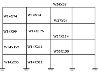
The three building frames to be investigated are all symmetric in the sway plane and comprise four bays with 4, 8, and 16 storys, respectively. All bays are 9.1 m wide and the story height is 4.2 m to first story level and 3.5 m subsequently. The buildings consist of special moment-resisting frames at each end that is parallel to the sway direction, with braced frames in the perpendicular direction [7]. The seismic design is based on the FEMA-350 provisions [10] for a special moment resisting frame on a rock profile located in seismic zone 4. A typical test frame is shown in Fig. 1. Details of the beam and column sections, double plate thickness and configuration of RBS connection, are given in Tables 1 to 3.
Fig 1. The four story frame.
Table 1. Details of the four story moment-resisting frame.
Table 2. Details of the eight story moment-resisting frame.
.
Table3. Details of the sixteen story moment-resisting frame.
assessed for each of the building frames considered, as defined below:
A - No beams have RBS connections. B - All beams have RBS connections.
C - Only beams on one side of the sway frame have RBS connections.
D - Only beams above the mid-height of the building have RBS connections.
E - Only beams below the mid-height of the building have RBS connections.
Wherever an RBS connection is used, it is always of the reduced web type shown in Figs. 2 (a) and (b) below
Fig. 2(a) Fig. 2(b) where a=0.4d, b= 1.7d, c=0.075d and d= depth of the beam. The basic properties of the steel were taken to be: Young’s modulus = 2.1 × 10⁵ MPa, Poisson’s ratio = 0.3, yield stress = 240 MPa, ultimate tensile strength = 370 MPa and the tangent modulus = Young’s modulus / 100.
V. NUMERICAL PROCEDURE
Force-displacement curves have been determined for each of the three frames considered under both monotonic and cyclic loading. The monotonic loading is applied at both the top story and foundation levels, while the cyclic loading is applied only at foundation level, where its magnitude is taken as the sum of the column reactions acting in the plane of each sway frame. The cyclic curve is based on the guide lines given in ATC-24[12].
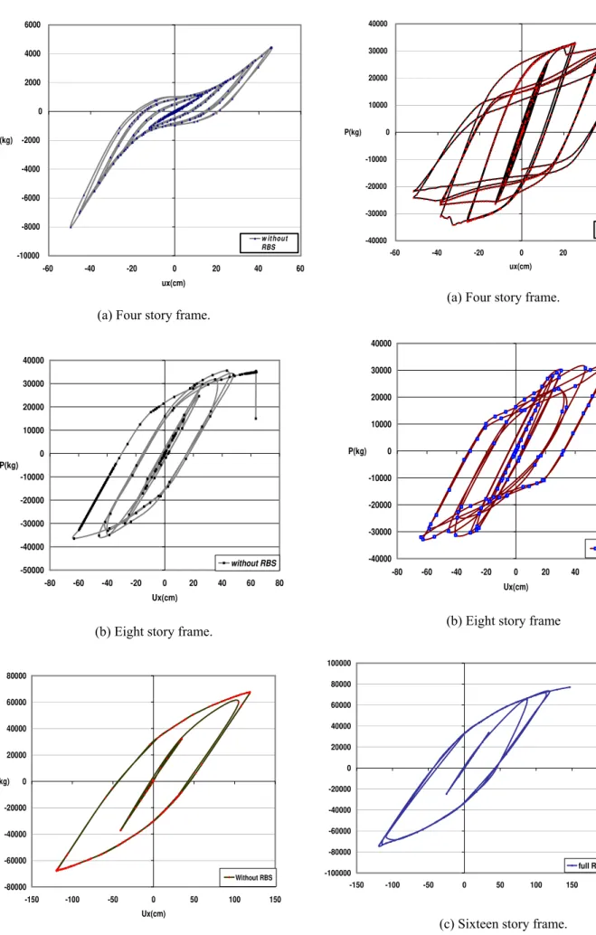
VI. NUMERICALRESULTS
The monotonic loading curves for the 4, 8 and 16 story buildings are shown in Fig. 3.
0 10000 20000 30000 40000 50000 60000
0 2 4 6 8 10 12 14 16
Ux (cm) P (kg)
(a) Four story frame.
0 5000 10000 15000 20000 25000 30000
0 5 10 15 20 25
Ux (cm) P (kg)
(b) Eight story frame.
0 5000 10000 15000 20000 25000 30000 35000 40000
0 50 100 150 200
Ux (cm) P (kg)
(c) Sixteen story frame.
Fig3. Monotonic force-displacement curves.
-10000 -8000 -6000 -4000 -2000 0 2000 4000 6000
-60 -40 -20 0 20 40 60
ux(cm) P(kg)
w it hout RBS
(a) Four story frame.
-50000 -40000 -30000 -20000 -10000 0 10000 20000 30000 40000
-80 -60 -40 -20 0 20 40 60 80
Ux(cm) P(kg)
without RBS
(b) Eight story frame.
-80000 -60000 -40000 -20000 0 20000 40000 60000 80000
-150 -100 -50 0 50 100 150
Ux(cm) P(kg)
Without RBS
(c) Sixteen story frame. Fig. 4. Connection arrangement A.
-40000 -30000 -20000 -10000 0 10000 20000 30000 40000
-60 -40 -20 0 20 40 60
ux(cm) P(kg)
full RBS
(a) Four story frame.
-40000 -30000 -20000 -10000 0 10000 20000 30000 40000
-80 -60 -40 -20 0 20 40 60 80
Ux(cm) P(kg)
full RBS
(b) Eight story frame
-100000 -80000 -60000 -40000 -20000 0 20000 40000 60000 80000 100000
-150 -100 -50 0 50 100 150 200
full RBS
-10000 -8000 -6000 -4000 -2000 0 2000 4000 6000
-60 -40 -20 0 20 40 60
ux(cm) P(kg)
one end RBS
(a) Four story frame.
-40000 -30000 -20000 -10000 0 10000 20000 30000 40000
-80 -60 -40 -20 0 20 40 60 80
Ux(cm) P(kg)
0ne end RBS
(b) Eight story frame.
-80000 -60000 -40000 -20000 0 20000 40000 60000 80000
-150 -100 -50 0 50 100 150 200
Ux(cm) P(kg)
one end RBS
(c)Sixteen story frame. Fig. 6. Connection arrangement C.
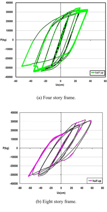
-40000 -30000 -20000 -10000 0 10000 20000 30000 40000
-60 -40 -20 0 20 40 60
Ux(cm) P(kg)
ha lf up
(a) Four story frame.
-40000 -30000 -20000 -10000 0 10000 20000 30000 40000
-80 -60 -40 -20 0 20 40 60 80
Ux(cm) P(kg)
hulf up
(b) Eight story frame.
-80000 -60000 -40000 -20000 0 20000 40000 60000 80000
-150 -100 -50 0 50 100 150 200
Ux(cm) P(kg)
hulf up
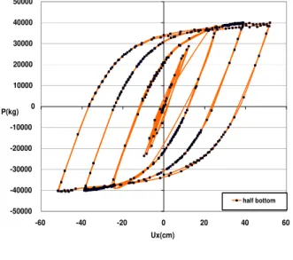
-50000 -40000 -30000 -20000 -10000 0 10000 20000 30000 40000 50000
-60 -40 -20 0 20 40 60
P(kg)
Ux(cm)
half bottom
(a) Four story frame.
-50000 -40000 -30000 -20000 -10000 0 10000 20000 30000 40000 50000
-80 -60 -40 -20 0 20 40 60 80
Ux(cm) P(kg)
bottom hulf
(b) Eight story frame.
-100000 -80000 -60000 -40000 -20000 0 20000 40000 60000 80000 100000
-150 -100 -50 0 50 100 150 200
Ux(cm) P(kg)
half bottom
(c) Sixteen story frame. Fig. 8. Connection arrangement E.
VI. ADDITIONAL BENEFITS RBS CONNECTION THAT UTILISES A REDUCED WEB
The plastic modulus of a universal beam section is proportional to the square of the depth of the section, but only linearly proportional to the width of the flange. Therefore, reducing the depth of the section has a greater effect on the plastic modulus than reducing the width of the section. The plastic moment capacity of the section is given by
Mp = Zpσy (1)
where σy is the yield stress of the material. Thus if the section
depth is reduced to induce the plastic hinge, this has the advantage of reducing the plastic moment capacity of the section much more quickly than tapering the flanges and with less change in the overall properties of the beam under normal loading situations. The beam is also made more compact and thus less likely to undergo lateral torsional buckling, one of the problems associated with the “dogbone” connection detail. A final advantage is that RBS connections require less construction time on site and use less material to produce a neater and smaller connection. [1]
VII. CONCLUSIONS
A new connection has been presented that is more efficient than those that have been presented previously. Numerical studies have shown that such a connection is structurally efficient in dissipating the energy of an earthquake and that there is one particular configuration, connection arrangement E, that yields optimum performance. A further important conclusion that can be drawn is that when retrofitting tall buildings, it is not necessary to retrofit RBS connections in every story.
REFERENCES
[ 1] S. Wilkinson et al,” A moment resisting connection for earthquake resistant structures “Journal of Constructional Steel Research 62 (2006) 295–302
[2] Iwankiw, N. ,(2004), Seismic design enhancement and the reduced beam section detail for steel moment frames, Practice Periodical on Structural design and
Construction, ASCE 9, 87-92.
[3] Zekioglu A, Mozaffarian H, Uang CM. Moment frame connection development and testing for the city of hope national medical center. In: Building to last, proceedings of structures congress XV, ASCE; 1997.
[4] Engelhardt MD, Venti M, Fry GT, Jones S, Holliday S. Behavior and design of radius cut reduced beam section connections. A draft report of SAC task 7.07a. SAC Joint Venture; 2000.
[5] Gilton CS, Chi B, Uang CM. Cyclic testing of rbs moment connections: weak axis configuration and deep column effects. SAC report 00/23, SAC Joint Venture; 2000.
[6] Gilton CS, Uang CM. Cyclic response and design
connections. Journal of Structural Engineering, ASCE 2002;128(4):452–63.
[7] Jin J. Seismic performance of steel RBS moment frame buildings. Ph.D. dissertation, Department of Civil and Environmental Engineering, University of Central Florida; 2002.
[8] Lee K, Foutch DA. Performance evaluation of new steel frame buildings for seismic loads. Earthquake Engineering and Structural Dynamics 2002;31:653–70.
[9] FEMA 302. NEHRP recommended provisions for seismic regulations for new buildings and other structures, part 1—provisions. Federal Emergency Management Agency, Washington, DC; 1997.
[10] FEMA 350. Recommended seismic design criteria for new steel moment-frame buildings. Prepared by the SAC Joint Venture for the Federal Emergency Management Agency, Washington, DC; 2000.
[11] Canonsburg, PA. “ANSYS Structural Analysis Guide, Release 10.0” SAS. IP, Inc., 2002