Marcelo F. Motta
[email protected] Federal University of Ceará - UFC Materials and Metallurgical Eng. Department 60455-760 Fortaleza, CE. Brazil.
Jair Carlos Dutra
Raul Gohr Jr
[email protected] Federal University of Santa Catarina - UFSC Mechanical Engineering Department 88040-900 Florianópolis, SC. Brazil
Américo Scotti
Member, ABCM [email protected] Federal University of Uberlândia - UFU Faculty of Mechanical Engineering 38400-902 Uberlândia, MG. Brazil
A Study on Out-of-Phase Current
Pulses of the Double Wire MIG/MAG
Process with Insulated Potentials on
Coating Applications – Part I
The part 1 of this work presents a study about the use of the out-of-phase current pulses technology applied to the Double Wire MIG/MAG welding process with Insulated Potentials on welded coating. High-speed digital back-lighted images were recorded to evaluate the influence of the levels of out-of-phase current pulses on the behavior of both metallic transfer modes and voltaic arcs configurations. The results showed that, with the electrodes positioned side by side and the mean currents below the transition current, the out-of-phasing parameter setting reduces the deviations of the arcs and changes the paths of the droplets. However, no significant effect was noticed on bead finishing or arc stability.
Keywords: welding, MIG/MAG; double wire; out-of-phase pulsed current
Introduction
The most popular version of the Double Wire MIG/MAG welding process uses two electrically insulated electrodes, which are melted together on a single molten pool. Due to the characteristic of providing a high-rate of material deposition, the process was used initially in the welding of thick plates (Lassaline, 1989). However, its greatest application has been mainly in the welding of sheets with high welding speed, which may reach more than 2 m/min (Brown, 1975; Hackl, 1997; Michie, 1999; Motta, 2001).
The objective of getting high productivity conflicts with the philosophy of the use of pulsed current in MIG/MAG. Pulsed current was developed to control metal transfer in order to reproduce the spray transfer at low current (below transition current). It would be simpler to increase productivity by raising current and using spray transfer or even buried short-circuit metal transfer. However, in several works found in the literature (Michie, 1999; Hackl, 1997; Voropay & Protsenko, 2000; Trommer, 2002; among others) and, mainly, in industrial applications, the pulsed current, with mean levels above the transition current, has been used to reach high melting rates.1
It has been claimed indiscriminately, mainly by equipment manufactures, that the use of pulsed current improves the performance of the Double Wire MIG/MAG welding process with insulated potentials, despite the a greater complexity of the equipment and difficulties for parameter settings, when compared to no-pulse welding. In addition, equipment manufactures have incorporated technological details that are presented as the most relevant factor to adequate weld results, such as the lag time between the current pulses of the leader and slave arcs (Fig. 1). This is claimed to reduce the electromagnetic interaction (arc blow) between the arcs, providing better stability (Lassaline, 1989; Hackl, 1997; Michie, 1999; Voropay & Protsenko, 2000; Trommer, 2002). However, in order to reach a high mean current as it is applied in
Paper accepted December, 2006. Technical Editor: Anselmo Eduardo Diniz.
industry, the background current should assume values that are high enough to cause strong electromagnetic interaction with the other voltaic arc at the pulse period. Thus, if the duration of the background current is very short and the values of background and pulse currents are high, the desired condition of a drop per pulse for welding with pulsed current will not be obtained (actually, the so-called Pulsed Double Wire MIG/MAG should be named high-frequency pulsing Double Wire MIG/MAG).
Another aspect that should be considered is that, in many practical cases, to guarantee sound beads with the double wire at high welding travel speed, one should weld with short arcs (buried in the molten pool). In those circumstances, a question to be raised is: would it not be easier and cheaper to work with steady DC current, once the arcs are short and the electromagnetic effect is minimized?
These considerations have not yet been well discussed in the literature, although the technology of out-of-phase current pulses has already been inserted in the main double wire systems available in the market, as well as been used in applications of the process in an indiscriminate way.
This article, divided in two parts, aims to study the effects that out-of-phasecurrent pulses can cause on metal transfer and on the behavior of the voltaic arcs (Part 1). In addition, it seeks to verify the consequences of these effects on the geometric profile of the deposits (Part 2). In general, the study intends to discuss the real benefits credited to the technology for welded coating applications.
Nomenclature
Ar = argon
CO2 = carbon dioxide
DC = direct current Ib = background current, A Im = mean current, A Ip = pulse current, A lt = lag time, ms
tp = pulse time, ms
TS = welding travel speed, cm/min WFS = wire feed speed, m/min
Greek Symbols
α
= level of significance σ = standard deviation
σUp A1 = standard deviation of the mean voltage in the pulse period for the arc of the electrode 1, V
σUb A1 = standard deviation of the mean voltage in the background period for the arc of the electrode 1, V σUp A2 = standard deviation of the mean voltage in the pulse
period for the arc of the electrode 2, V
θ
=angle of droplet deviation,o
θ
e= angle of left hand droplet deviation,o
θ
d= angle of right hand droplet deviation, o
Experimental Procedure
All the weldments done in this study were carried out using two microprocessor-based power sources with nominal current capacity of 450 A at 100% duty cycle. An electronic circuit was implemented to link them in such a way that the beginning of the current pulsation of one of the sources (slave power source) was commanded by the other one (master power source). The lag time between the current pulses (“lt” - the time that the slave power source delays the beginning of its pulsation in relation to the beginning of the master power source pulses) could be set by the user, as shown in Fig. 1.
The welding trials had the main objective of simulating coating welding, so that the two electrodes were positioned one beside the other in relation to the welding direction (“side by side”). The electrodes used were 1.0-mm-diameter AWS ER70S-6 class and the contact-tip to plate surface distance was 16 mm. The guns were fixed at an angle of 13o, resulting in a distance between the electrodes tips of approximately 8 mm, in the area of the molten pool, (Fig. 2). As shielding gas, a mixture with 96% of Ar and 4% of CO2 was used at a flow of 10 l/min in each gun. The signals of
arc voltage and welding current of both arcs were acquired for 5s by means of a data-log system at a frequency of 4 kHz for each signal and with resolution of 12 bit.
Figure 1. Schematic oscilograms of the welding current signal imposed by the two power sources, where lt = lag time between pulses and tp = pulse duration: a) Out-of-phasecurrent pulses, in which lt > tp; b) Out-of-phase current pulses, in which lt < tp; c) In phase current pulses, i.e., lt = 0 ms.
Figure 2. Angle of 13 degrees between the guns.
In the first part of the work, the experiments were divided in two stages. In the first one, high-speed filming was carried out with the objective of evaluating the metallic transfers and the behavior of the voltaic arcs under the influence of the out-of-phase current pulses. In the second stage, the experiments were done with the purpose of pointing out the differences in the current pulsation conditions with regard to the superficial finish of the deposits (with and without the out-of phase current pulses).
Characterization of the Out-of-Phase Current Effect on the Arcs
It was sought, through the shadowgraph technique and high-speed filming (Balsamo et al, 2000), to visualize the arcs and metal transfers during actual welding with the Double Wire MIG/MAG process. The bead-on-plate welds were deposited on a rotating tube (Fig. 3). For each weld, a tube of plain carbon steel SAE/AISI 1010 type, of 4-mm-thick, 150-mm-long and 90-mm-external diameter tubes was used. It was intended, by the use of a tube, to avoid that part of the arcs became hid by the molten pool during image recording.
Figure 3. Schematic representation of the welding rig for filming the arcs.
Three levels of current lagtime (lt) were investigated (Fig. 1): a) Pulses from the master power source quite ahead of the ones from the slave power source (lt > tp); b) Pulses from the master power source just ahead of the ones from the slave power source (lt < tp); c) lt = 0. These three distinct conditions of pulsation were analyzed at three levels of mean current (80, 120 and 160 A/wire). The choice of current levels below the transition current for this pair electrode-wire/protection gas aimed at providing a smoother transfer and easier visualization. The Table 1 presents the sequence of experiments made, in which columns 8 and 9 introduce the wire feed speeds set in order to result in arc lengths of approximately 5 mm for the given parameter combinations. The travel speeds varied in each experiment to avoid arc burn-through.
Table 1. Conditions of welding used in the experiments of the first stage.
Pulsation Settings WFS
(m/min) Im/wire
(A) Ip
(A) tp (ms)
Ib (A)
tb (ms)
lt (ms)
TS (cm/min) Wire
1 Wire
2
80 280 3.3 48 20.5 10.2 17.0 3.0 2.8
80 280 3.3 48 20.5 2.0 17.0 3.0 2.8
80 280 3.3 48 20.5 0.0 17.0 3.0 2.8
120 280 3.3 77 12.4 7.8 20.0 4.5 4.2
120 280 3.3 77 12.4 2.0 20.0 4.5 4.2
120 280 3.3 77 12.4 0.0 20.0 4.5 4.2
160 280 3.3 109 6.3 5.5 22.6 6.4 6.1
160 280 3.3 109 6.3 2.0 22.6 6.4 6.1
160 280 3.3 109 6.3 0.0 22.6 6.4 6.1
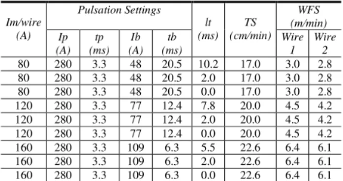
The responses analyzed were the deviation of the arcs and the paths of the droplets after detachment. Some sequences of images of detached drops were captured. The position of these drops could be registered through a by using an image analysis software available in the market. Figure 4 illustrates a sequence of images of droplet displacement in which the variation of their paths is given by the angle "
θ
". Five samples of sequences of images were taken from each one of the nine experiments presented in Table 1, totaling 45 measurements for each electrode.
Figure 4. Example of a transfer sequence and the respective graphic representation of the drop path. lt = 0 ms and mean current (Im) = 80 A (θ e = 30˚ and θ d = 16˚).
Stage 2: Effect of the Deviation of the Arc on Coating Formation Over Plates in Overhead Position
Compared to welding in down hand position, the overhead welding presents deposit is an obstacle to the metallic transfer, and the voltaic arc instabilities in this position cause imperfections in the weld bead more easily (as, for example, lack of smoothness, porosity, undercut and lack of fusion). The welds at this stage were done to point out differences caused by the current pulsation conditions in the superficial finishing of multi-layered deposits. As seen in Fig. 5, side-by-side positioned guns deposited beads on a plate tilted by 45o (overhead position), with the help of a robot. The welding direction was descending, as indicated by the arrow "LD". For carrying out these experiments, just one factor – current lag time - was studied at three levels: a) The pulses from the sources were out-of-phase with lt > tp (Fig. 1a); b) In-phase pulses, i.e., lt = 0 (Fig. 1c); c) random pulses, in which there was not control over the timing of current pulsation of both arcs.
The welding procedure consisted in making two superimposed layers of weld beads on carbon steel plates (SAE/AISI 1010 - DIN St 34), cut in the dimensions of 12.5 x 100 x 200 mm. Each layer was composed of seven equally spaced weld beads. The distance between weld beads corresponded approximately to half width of a weld bead (8 mm). Table 2 shows the welding conditions set to carry out the welding.
Figure 5. Position and direction of the gun displacement during the overhead trials.
Table 2. Welding conditions used in the experiments.
WFS (m/min)
Im/wire (A) lt (ms) TS (cm/min)
Wire 1 Wire 2
120 7.8 40 5.1 4.9
120 0.0 40 5.1 4.9
120 At Random 40 5.1 4.9
Results and Discussions
Characterization of the Out-of-Phase Current Effect on the Arcs
An illustration of the arc path deviations as a function of peak current lag times can be seen in Fig. 6.
(a) (b) (c)
Figure 6. Images of the arc region with Ip = 280 A, Ib = 50 A and Im = 80 A: a) Left hand arc is at the period of current pulse and the right hand arc at the background (lt = 10,2 ms); b) The same as in a), but the right hand arc is at the pulse period (lt = 10,2 ms); c) Both are at the pulse period (lt = 0,0 ms).
In Fig. 6a, the arc on the left is in the period of current pulse. Therefore, it appears brighter than the one on the right, which, in turn, at the same time, is in the background period. Similarly, the same occurs for the other electrode in Fig. 6b. When the currents of both arcs are pulsing at the same time (Fig. 6c), the deviations of these arcs appear to be greater. This behavior is expected theoretically (and mentioned in the literature), based on the action of electromagnetic forces created by each voltaic arc, and is proportional to the intensity of the currents that flow through them.
However, it was observed is that, together with arc deviation, there was a similar deviation of the droplets from their paths, as shown in Fig. 4 and Fig. 7.
Figure 7. Deviation angle of droplet θ = 6º: the left electrode pulse current at the moment of the droplet detaching is of 280 A and of the right electrode is of 50 A (Im = 80 A and lt = 10,2 ms).
The path of a droplet is defined by the intensity of the deflection of the arc at the instant of the droplet detachments. Thus, arcs pulsing at the same time presented a greater drop deflection (Fig. 4). It should be pointed out that the welding parameters were set to each arc so that it had the condition of one drop per pulse.
Another aspect that calls attention in Fig. 8 is the greater deflection suffered by the left arc (fed by the principal source) than to the right one. As a consequence, the deviations of the droplets detaching from this electrode were more accentuated. The welding conditions were similar for both arcs. However, as shown in Fig. 3, the electrode on the left side is closer to the earth cable and further away from the edge of the tube, so it is suspected that a greater electromagnetic interference occurred on the left electrode.
The deviations of the voltaic arcs, as well as the paths of the droplets, can modify the profile of the weld penetration. Essers & Walter (1981) observed that, in the MIG/MAG process with one wire, the weld penetration profile could be altered by controlling the path of the transferred metallic drops. This control was made by an alternating magnetic field applied in a direction transversal to the arc. Through changes in the oscillation frequency of this field, the authors managed to direct the droplets towards specific points of the weld pool and, consequently, the profile of the weld penetration could be modified.
Figure 8. Angle "θ " of droplet deviation. lt = lag time and tp = pulse duration.
The possibility of modifying the profile of penetration of the weld bead and applying this process in coating weldings motivates the conducting of welding in plates with the aim of observing the effects of out-of-phase current pulses on the geometric profile of the weld beads. This study will be presented in a second paper to be published in this journal.
Stage 2: Effect of the Deviation of the Arc on Coating Formation Over Plates in Overhead Position
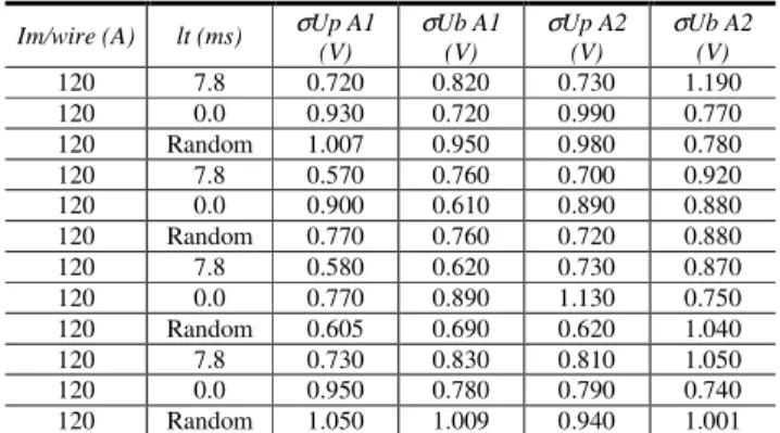
The employed welding conditions in these trials were presented in the Table 2. For each condition, four acquisitions of the arcs voltage signals were made. The standard deviations (σ) of the arc voltage signals in the pulse and background periods were calculated and used to evaluate the stability of the arcs. Table 3 presents these values. It was aimed, through the standard deviation, to verify if the modifications in the out-of-phase current pulse conditions altered significantly the voltaic arc length and, consequently, if they caused oscillations in the welding voltage. A variance analysis was applied to these results and the values of the level of significance “α ” are
presented in Table 4. According to these values, it was understood that the lag time did not significantly influenced the standard deviations of voltage either in the pulse or background periods of current.
The results also showed that, for the types of current pulsation (lt > tp, lt = 0 and at random), the deviations of the arcs did not cause significant oscillation in the voltage of each arc. It could be confirmed that the superficial quality of the weld beads was not
influenced either, as shown in Fig. 9a, 9b and 9c. It is noticed that the surface finish, considering the smoothness of the weld beads, was similar among the three analyzed conditions (wide and smooth weld beads).
These geometric characteristics of the weld beads show the potential that the process presents for coating applications. With regards to spatter formation, it is noticed that it was low for the three conditions of current pulsation. Some observed irregularities of the weld beads which occurred, were probably due to some interruption in the feeding of the wires. Penetrant Liquid testing on the bead upper layer showed no presence of pores and cracks.
Table 3. Standard deviations of the mean voltage in the pulse and background periods.
Im/wire (A) lt (ms) σUp A1
(V)
σUb A1 (V)
σUp A2 (V)
σUb A2 (V)
120 7.8 0.720 0.820 0.730 1.190
120 0.0 0.930 0.720 0.990 0.770
120 Random 1.007 0.950 0.980 0.780
120 7.8 0.570 0.760 0.700 0.920
120 0.0 0.900 0.610 0.890 0.880
120 Random 0.770 0.760 0.720 0.880
120 7.8 0.580 0.620 0.730 0.870
120 0.0 0.770 0.890 1.130 0.750
120 Random 0.605 0.690 0.620 1.040
120 7.8 0.730 0.830 0.810 1.050
120 0.0 0.950 0.780 0.790 0.740
120 Random 1.050 1.009 0.940 1.001
Note: σUxAY stands for standard deviation (σ) of the mean voltage either in the pulse period (Up) or background period (Ub) for the arc of either the electrode 1 (A1) or electrode 2 (A2)
Table 4. Level of significance (α ) of the effect of the lag time on the standard deviations of voltage in pulse and background periods of current.
Factor σUmpA1 (V) σUmbA1 (V) σUmpA2 (V) σUmbA2 (V)
Lag time 0.076 0.460 0.137 0.060
(a)
(b) (c)
Figure 9. Photos of the layers deposited at a mean current of 120 A/wire: a) lt > tp; b) lt = 0; c) at random.
Conclusions
For plain carbon steel, with a “side by side” positioning of the electrodes, mean current below the transition current and other welding conditions adopted in this work, it can be concluded that:
• The deviations of the arcs deviates the droplets from their path during metal transfer, possibly influencing the formation of the melting pool;
• Having, as the evaluation criteria for arc stability, the standard deviation of arc voltage in the pulse and background periods of current, it can be said that out-of-phase current pulses did not have a statistically significant influence on the stability of the arcs;
• Having, as the evaluation criteria, the surface finish of the deposits, the amount of spatters and the porosity presence, there were not significant differences between the deposits carried out with or without the out-of-phase current pulses technology;
• Finally, within the conditions in which this work was carried out, these results show that the out-of-phase technology may not be essential for an adequate performance of the Double Wire MIG/MAG welding process.
References
Bálsamo, P.S.S., Vilarinho, L. O., Vilela, M. & Scotti, A., 2000, “Development of an Experimental Technique for Studying Metal Transfer in Welding: Synchronized Shadowgraphy”, The Int. Journal for the Joining of
Materials, vol 12, no. 1, 2000, The European Institute for Joining of Materials (JOM), Denmark, pp. 1-12
Brown, K. W., 1975, “Introducing the Switched-Arc Welding Process”, Welding Institute Research Bulletin, 1975, 16 (6), p. 172-175.
Essers, W. G. & Walter , R., 1981, “Heat Transfer and Penetration Mechanisms with GMA and Plasma-GMA Welding”, Welding Journal, no 2 February, 1981, p. 37s-42s.
Hackl, H., 1997, “Faster with Two Wire Electrodes Metal Inert Gas Welding of Aluminium Materials”, Exploiting Advances in Arc Welding Technology, TWI, Abington, U.K. 1997.
Lassaline, B. Et Al, 1989, “Narrow Groove Twin-Wire MIG/MAG of High-Strength Steel”, Welding Journal, 9, Sep 1989, pp. 53-58.
Michie, K., Blackman, S. & Ogunbiyi, T. E. B., 1999, “Twin Wire GMAW: Process Characteristics and Applications”, Welding Journal, 5, May 1999, pp. 31 a 34.
Motta, M. F. & Dutra, J. C., 2001, “A Discussion over the Pulsed Current Utilization in the Double Wire MIG/MAG Process with Insulated Potentials”, XXVII National Welding Congress, ABS, São Paulo, Brazil, CT-23, 2002 (in Portuguese).
Trommer G., 2002, “Welding with Two Wire Electrodes – Status and Prospects of the Optimisation of Gas – Shielded Metal – Arc Welding”, Welding and Cutting, no 3, 2002, pp. 122-125