*e-mail: [email protected]
1. Introduction
Nitride transition metal thin ilms have been used in the last decades due to properties as hardness and wear resistance1-3.
Zirconium nitride (ZrN) is a typical coating used because its tribological properties, besides corrosion and oxidation resistance. Even with differentiated properties, ZrN thin ilms present columnar microstructure, micro-cracks and pores, which are defects associated with transition metals nitrides deposited by PVD and CVD techniques. These coatings characteristics allow direct contact between the external environment and the substrate, compromising the mechanical properties and its applications in high temperature or corrosive environments4-6.
It is important to note that ZrN thin ilms mechanical properties are associated with a complex state of compression of the crystalline lattice (residual stress). The deposition process is usually carried out at low temperatures (T < 300 °C) inhibiting ZrN molecules to achieve its equilibrium state in the lattice structure. The result is that the crystalline lattice remains in a metastable condition and, consequently, the structure can be changed if the necessary activation energy is
provided to the system, resulting in degradation of coatings properties7-9.
An alternative to modify ZrN thin ilms microstructure and morphology is the addition of a third element as silicon. The Si addition promotes a two phase microstructure formation: a crystalline (ZrN) and an amorphous phase (Si3N4).
The amorphous phase is located at the grain boundaries and contributes to reduce the ZrN grain size, since it increases the ZrN grains nucleation rate. The inal grain size is less than 10 nm, resulting in the formation of a nanocomposite structure. These characteristics have potential to change thin ilm morphology and macroscopic properties10-12.
This type of microstructure is dense, homogeneous and not signiicantly affected by diffusion activated processes, which means that it has a high thermal stability13-17. But, properties
and microstructure of ZrSiN thin ilms are function of silicon concentration and deposition techniques (PVD or CVD) parameters. So, although many studies demonstrate the advantages of adding silicon to nitride thin ilms, there are gaps and discussions about microstructure formation and inluence of Si content and deposition parameters on coatings physical and chemical properties2,3,7-17.
Structural and Mechanical Properties of Zr-Si-N Thin Films
Prepared by Reactive Magnetron Sputtering
Flávio Gustavo Ribeiro Freitasa*, Roberto Hüblerb, Gabriel Soaresc,
Amanda Gardênia Santos Conceiçãoa, Edson Reis Vitóriaa, Renata Gomes Carvalhoa,
Eduardo Kirinus Tentardinia
aDepartamento de Ciência e Engenharia de Materiais, Universidade Federal de Sergipe – UFS, Avenida Marechal Rondon, s/n, CEP 49100-000, São Cristóvão, SE, Brazil
bInstituto de Física – GEPSI, Pontifícia Universidade Católica do Rio Grande do Sul – PUCRS,
Avenida Ipiranga, 6681, CEP 90619-900, Porto Alegre, RS, Brazil cInstituto de Física, Universidade Federal do Rio Grande do Sul – UFRGS,
Avenida Paulo Gama, 110, CEP 90040-060, Porto Alegre, RS, Brazil
Received: October 24, 2014; Revised: June 16, 2015
Zirconium silicon nitride (ZrSiN) thin ilms were deposited by reactive magnetron sputtering in order to verify the silicon inluence on coating morphology and mechanical properties. The Si/(Zr+Si) ratio was adjusted between 0 to 15% just modifying the power applied on the silicon target. Only peaks associated to ZrN crystalline structure were observed in XRD analysis, since Si3N4 phase was
amorphous. All samples have (111) preferred orientation, but there is a peak intensity reduction and a broadening increase for the sample with the highest Si/(Zr+Si) ratio (15%), demonstrating a considerable loss of crystallinity or grain size reduction (about 8 nm calculated by Scherrer). It was also observed that the I(200)/I(111) ratio increases with silicon addition. Chemical composition and thickness of the coatings were determined by RBS analysis. No signiicant changes in nanohardness with increasing Si content were found. The morphology observed by FEG-SEM presents non columnar characteristics for thin ilms with silicon addition. The set of results suggests that Si addition is restricting the columnar growth of ZrN thin ilms. This conclusion is justiied by the fact that Si contributes to increase the ZrN grains nucleation during the sputtering process.
The study proposal was to deposit thin ilms of ZrSiN system by reactive magnetron sputtering (RMS) varying the Si concentration in each coating. Grazing Angle X-ray diffraction (GAXRD), Field Emission Scanning Electron Microscopy (FEG-SEM), Rutherford Backscattering Spectroscopy (RBS) and nanohardness techniques were used to analyze coatings morphology and mechanical properties.
2. Material and Methods
Thin ilms used in this work were co-deposited by reactive magnetron sputtering with an AJA Orion 5-HV Sputtering Systems model with two independents targets, Zr and Si, with purity of 99.7 at% and 99.5 at %, respectively. Before deposition, substrates were underwent ultrasonic cleaning in acetone during 30 minutes, washed with ethyl alcohol (54°) and then dried. The chamber was preconditioned to a base pressure of 1×10⁻⁷ Torr and targets were bombarded ionically
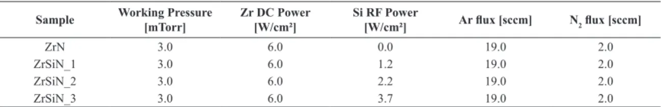
to remove oxide layers from the surface before deposition. All deposition parameters were maintained constant during depositions except the power used at silicon target, as showed in Table 1. The distance target-substrate applied in all depositions was 120 mm and two different types of substrates were used according to the characterization technique: silicon wafer for GAXRD, nanohardness and FEG-SEM analysis and polyethylene plates for RBS studies. The thickness and deposition time was also adjusted to comply with the required analysis, 50 nm and 12 minutes for RBS samples, 300 nm and 60 minutes for FEG-SEM and GAXRD samples and 600 nm and 120 minutes for nanohardness samples. No external heating was applied to the substrates.
GAXRD patterns were performed on a Shimadzu XRD-6000 model (Cu-Kα radiation; λ = 1.54 Å) with grazing angle of 1°. The morphology of the ilm cross section was observed on a high-resolution FEG-SEM JSM-6330F.
Nanohardness analyses were performed in a Fisherscope HV 100 with a Berkovich indenter and indentation depth of 40 nm. This technique also permits to determine the ilms Young’s modulus. RBS analysis were performed using a 3 MV tandetron with alpha particles accelerated up to 2 MeV, with a silicon based detector at an angle of 165° and resolution of 12 keV.
3. Results and Discussion
Stoichiometric zirconium nitride thin ilms has a metallic gold color18 and the ZrN coating deposited in this work with
Ar/N2 ratio of 19/2 presented this characteristic. A set of
ZrSiN thin ilms modifying Si concentration were deposited using different powers applied on the silicon target. These samples were analyzed by RBS technique to measure coatings
thickness, identify chemical elements and their respective concentrations. All samples present similar results, except the silicon peak, which is function of the power applied to the Si target. For this reason it is presented in Figure 1 just the RBS analysis for sample ZrSiN_3.
Analyzing Figure 1 is possible to identify the presence of Hf, Zr, Si, N and O from thin ilm and C from substrate and these chemical elements were detected for all samples. The hafnium presence is due the contamination of this chemical element on Zr target, once by manufacturer data the target is 99.7% Zr and 0.3% Hf. RBS results also show that the ilms are near the stoichiometric concentration, conirming the Ar/N2 ratio of 19/2. The areal densities of
zirconium and nitrogen chemical species were determined using a Sb implanted silicon standard.
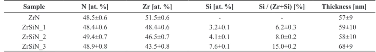
Table 2 shows Zr, N and Si concentration in at.% and Si/(Zr+Si) ratio determined by RBS for all samples. The coatings Si/(Zr+Si) ratio were characterized as low (6.2 %), intermediary (8.0 %) and high (15.0 %), for sample ZrSiN_1, ZrSiN_2 and ZrSiN_3, respectively. The coatings thickness was estimated in approximately 60 nm for all samples.
Figure 2 shows the GAXRD analysis for all samples. The ZrN, ZrSiN_1 and ZrSiN_2 XRD patterns are almost identical, but the ZrSiN_3 has a peak intensity reduction and a small increase in (111) peak width, demonstrating a considerable loss of crystallinity or grain size reduction. Si3N4
structure is amorphous (conirmed by GAXRD analysis) and its presence causes the reduction of diffraction peaks intensity.
Si3N4 particles contribute to ZrN grain nucleation process
during ilm growth, resulting in a structure with reduced grain size10,19. The crystallite size calculated by Scherrer for ZrSiN_3 is about 8 nm (nanocomposite structure), while
Table 1. Sputtering deposition parameters – only power applied to silicon target was changed in thin ilms samples.
Sample Working Pressure [mTorr]
Zr DC Power [W/cm²]
Si RF Power
[W/cm²] Ar lux [sccm] N2 lux [sccm]
ZrN 3.0 6.0 0.0 19.0 2.0
ZrSiN_1 3.0 6.0 1.2 19.0 2.0
ZrSiN_2 3.0 6.0 2.2 19.0 2.0
ZrSiN_3 3.0 6.0 3.7 19.0 2.0
for others ilms is 11 nm. A small peak at 54° was found for all samples and is probably associated with ZrO2 or
ZrSiO4 phases.
Reference pattern ICDD PDF 35-0753 presented in Figure 2 shows that the main peaks for ZrN are (111) and (200) orientations, with this last presenting an intensity of 70% compared with (111) peak. Comparing the ICDD pattern with the ZrN and ZrSiN coatings deposited on this work, it is clear the decreasing of (200) peak intensity, showing that there is a high fraction of (111) oriented grains when compared to others orientations, especially the (200) grains. It is important to note that as the silicon content is increased, it can be observed that I(200)/I(111) ratio is increased from 14.2% to 18.9%, showing that (200) grains growth during deposition is favored due the silicon content. These results can be better observed in Figure 3.
Grains with (200) orientation have the lowest surface energy, while (111) grains have the lowest deformation energy. Thin ilms deposited by sputtering have high defects concentration, which causes crystal lattice distortion and promotes the (111) preferred orientation due to deformation energy minimization20,21. Grains with (111) orientation grow in the normal direction to the ilm plane, which contributes to the formation of a columnar microstructure, while (200) grains grow in the parallel direction, having the potential to change the columnar morphology to a non columnar one22.
The silicon addition act as a nucleation center for ZrN grains, reducing the crystallite size and creating thermodynamic conditions to the (200) oriented grains. The (200) indicates that the system is minimizing the surface energy and it can be concluded that the amount of defects in the ilm is reduced, which can improve thin ilm properties and characteristics.
Figure 4 shows nanohardness results for ZrN and ZrSiN thin ilms. The ZrN hardness was determined in about 15.6 GPa, value consistent with literature. Samples ZrSiN_1, ZrSiN_2 and ZrSiN_3 had no signiicant variation in nanohardness. For ZrSiN_1 and ZrSiN_2 the Si addition in low concentration was not enough to change the structure and mechanical properties. But, for ZrSiN_3 the highest I(200)/I(111) ratio contributes to hardness reduction and, on the other hand, the lowest crystallite size and the microstructure composed by
ZrN and Si3N4 phases contributes to increase this mechanichal propertie23. The global result is no signiicant impact in
hardness for ZrSiN_3 sample.
Young’s modulus results (Figure 4) has similar trend as observed for hardness values and the same interpretations can be pointed out for this mechanichal propertie.
Figure 5 shows FEG-SEM of ZrSiN_2 thin ilm cross section with a non columnar structure. All ZrSiN coatings presented this same behavior. Silicon addition promoted a transition from a columnar morphology to a non columnar one as the Si content is increased. This microstructure is aligned
Table 2. RBS analysis to N, Zr and Si – chemichal concentrations and thin ilm thickness.
Sample N [at. %] Zr [at. %] Si [at. %] Si / (Zr+Si) [%] Thickness [nm]
ZrN 48.5±0.6 51.5±0.6 - - 57±9
ZrSiN_1 48.4±0.6 48.4±0.6 3.2±0.1 6.2±0.3 59±10
ZrSiN_2 49.4±0.7 46.5±0.7 4.1±0.1 8.0±0.2 58±10
ZrSiN_3 48.9±0.8 43.5±0.8 7.6±0.1 15.0±0.2 68±9
Figure 2. Grazing angle (1°) XRD analysis – (111) peak intensity reduction and broadening for ZrSiN_3 sample. It can be veriied the (111) preferred orientation for ZrN and ZrSiN thin ilms. The peaks intensities obtained from ICDD PDF 35-0753 are also presented.
Figure 3. Preferred orientation obtained from GAXRD 1° – I(200)/I(111) ratio is higher as Si content is increased.
with GAXRD results, conirming the Si potential to modify ZrN morphology by blocking the columnar structure growth. In other words, silicon atoms restricts the columnar growth due to an increase in ZrN grain nucleation rate, inhibiting the (111) orientation and favoring the (200) orientation.
It can be also veriied that the thin ilms observed by FEG-SEM are homogeneous and have apparently good adhesion.
4. Conclusions
ZrN and ZrSiN were successively deposited by reactive magnetron sputtering. RBS analysis show ZrN coatings with stoichiometric near to 1:1 and the Si/(Zr+Si) ratio of ZrSiN
coatings were determined as 6.2%, 8.0% and 15.0% when applied 1.2, 2.2 and 3.7 W/cm² at Si target, respectively. All coatings presented hafnium originated from zirconium
target.
GAXRD patterns show a (111) peak broadening and intensity reduction for sample ZrSiN _3, but maintaining the preferred orientation (111). The crystallite size calculated by Scherrer pointed out that silicon addition creates a nanocomposite structure.
All thin ilms present a high fraction of (111) oriented grains, however it is observed an increase in I(200)/I(111) ratio in function of silicon content. Silicon addition creates thermodynamic conditions to deposit (200) oriented grains, which causes a reduction in ilms defects concentration.
Nanohardness analysis indicated no significant modiication in hardness between ZrN and ZrSiN coatings. But, ZrSiN_3 sample has a set of characteristics that justiies the maintainability of its nanohardness (I(200)/I(111) ratio increase, crystallite size reduction and microstructure composed by two phases). Young’s modulus have the same behaviour observed for nanohardness analyses.
FEG-SEM results show ZrSiN thin ilms with a non columnar structure. Silicon addition blocks the columnar growth due to the favorable conditions to (200) orientation. Increasing the Si content in ZrN thin ilms promotes a transition from a columnar to a non columnar structure.
Acknowledgements
The author would like to thank PETROBRAS S.A. for the opportunity to develop this work, which is inserted on PETROBRAS Human Resources Development Program (PDRH), and also FAPITEC for inancial support. Figure 5. FEG-SEM image for ZrSiN_2 – it can be observed a
morphology composed by non columnar structure.
References
1. Musil J. Hard and superhard nanocomposite coatings. Surface and Coatings Technology. 2000; 125(1-3):322-330. http:// dx.doi.org/10.1016/S0257-8972(99)00586-1.
2. Benkahoul M, Sandu CS, Tabet N, Parlinska-Wojtan M, Karimi A and Lévy F. Effect of Si incorporation on the properties of niobium nitride films deposited by DC reactive magnetron sputtering. Surface and Coatings Technology. 2004; 188-189:435-439. http://dx.doi.org/10.1016/j.surfcoat.2004.08.048.
3. Veprek S and Veprek-Heijman MGJ. Industrial applications of superhard nanocomposite coatings. Surface and Coatings Technology. 2008; 202(21):5063-5073. http://dx.doi.org/10.1016/j.
surfcoat.2008.05.038.
4. Abadias G, Michel A, Tromas C, Jaouen C and Dub SN. Stress, interfacial effects and mechanical properties of nanoscale multilayered coatings. Surface and Coatings Technology. 2007; 202(4-7):844-853. http://dx.doi.org/10.1016/j.surfcoat.2007.05.068.
5. Lee J and Yang G. Preparation of TiAlN/ZrN and TiCrN/ ZrN multilayers by RF magnetron sputtering. Transactions
of Nonferrous Metals Society of China. 2009; 19(4):795-799.
http://dx.doi.org/10.1016/S1003-6326(08)60352-0.
6. Ma S, Prochazka J, Karvankova P, Ma Q, Niu X, Wang X, et al. Comparative study of the tribological behavior of superhard nanocomposite coatings nc-TiN/a-Si3N4 with TiN. Surface and Coatings Technology. 2005; 194(1):143-148. http://dx.doi.
org/10.1016/j.surfcoat.2004.05.007.
7. Veprek S, Veprek-Heijman MGJ, Karvankova P and Prochazka J. Different approaches to superhard coatings and nanocomposites.
Thin Solid Films. 2005; 476(1):1-29. http://dx.doi.org/10.1016/j.
tsf.2004.10.053.
8. Veprek S and Veprek-Heijman MGJ. Limits to the preparation of superhard nanocomposites: impurities, deposition and
annealing temperature. Thin Solid Films. 2012; 522:274-282.
http://dx.doi.org/10.1016/j.tsf.2012.08.048.
9. Veprek S, Mannling HD, Karvánková P and Procházka J. The issue of the reproducibility of deposition of superhard nanocomposites with hardness of ≥50 GPa. Surface and Coatings Technology. 2006; 200(12-13):3876-3885. http://
dx.doi.org/10.1016/j.surfcoat.2004.11.023.
10. Sandu CS, Sanjinés R and Medjani F. Control of morphology (ZrN crystallite size and SiNx layer thickness) in Zr–Si–N nanocomposite thin films. Surface and Coatings Technology. 2008; 202(11):2278-2281. http://dx.doi.org/10.1016/j.
surfcoat.2007.09.003.
11. Pilloud D, Pierson JF and Takadoum J. Structure and tribological properties of reactively Zr-Si-N films. Thin Solid Films. 2006; 496(2):445-449. http://dx.doi.org/10.1016/j.tsf.2005.09.062.
12. Sandu CS, Harada S, Sanjinés R and Cavaleiro A. A unique approach to reveal the nanocomposite nc-MN/SiN-layer architecture of thin films via electrical measurements. Surface and Coatings Technology. 2010; 204(12-13):1907-1913. http://
13. Sandu CS, Sanjinés R, Benkahoul M, Medjani M and Lévy F. Formation of composite ternary thin films by magnetron sputtering co-deposition. Surface and Coatings Technology. 2006; 201(7):4083-4089. http://dx.doi.org/10.1016/j.
surfcoat.2006.08.100.
14. Sandu CS, Medjani F, Sanjinés R, Karimi A and Lévy F. Structure, morphology and electrical properties of sputtered Zr–Si–N thin films: from solid solution to nanocomposite.
Surface and Coatings Technology. 2006; 201(7):4219-4223.
http://dx.doi.org/10.1016/j.surfcoat.2006.08.002.
15. Sandu CS, Benkahoul M, Sanjinés R and Lévy F. Model for the evolution of Nb–Si–N thin films as a function of Si content relating the nanostructure to electrical and mechanical properties.
Surface and Coatings Technology. 2006; 201(6):2897-2903.
http://dx.doi.org/10.1016/j.surfcoat.2006.06.003.
16. Sandu CS, Cusnir N, Oezer D, Sanjinés R and Patscheider J. Influence of bias voltage on the microstructure and physical properties of magnetron sputtered Zr–Si–N nanocomposite thin films. Surface and Coatings Technology. 2009; 204(6-7):969-972. http://dx.doi.org/10.1016/j.surfcoat.2009.06.042.
17. Patscheider J, Zehnder T and Diserens M. Structure–performance relations in nanocomposite coatings. Surface and Coatings Technology. 2001; 146-147:201-208. http://dx.doi.org/10.1016/ S0257-8972(01)01389-5.
18. Lamni R, Martinez E, Springer SG, Sanjines R, Schmid PE and Levy F. Optical and electronic properties of magnetron sputtered ZrNx thin films. Thin Solid Films. 2004; 447-448:316-321.
http://dx.doi.org/10.1016/S0040-6090(03)01109-X.
19. Musil J. Hard nanocomposite coatings: thermal stability, oxidation resistance and toughness. Surface and Coatings Technology. 2012; 207:50-65. http://dx.doi.org/10.1016/j.
surfcoat.2012.05.073.
20. Abadias G. Stress and preferred orientation in nitride-based PVD coatings. Surface and Coatings Technology. 2008; 202(11):2223-2235. http://dx.doi.org/10.1016/j.surfcoat.2007.08.029.
21. Goldfarb I, Pelleg J, Zevin L and Croitoru N. Lattice distortion in thin films of IVB metal (Ti, Zr, Hf) Nitrides. Thin Solid Films. 1991; 200(1):117-127. http://dx.doi.org/10.1016/0040-6090(91)90034-U.
22. Banerjee R, Chandra R and Ayyub P. Influence of the sputtering gas on the preferred orientation of nanocrystalline titanium nitride thin films. Thin Solid Films. 2002; 405(1-2):64-72. http://dx.doi.org/10.1016/S0040-6090(01)01705-9.
23. Procházka J, Karvánková P, Veprek-Heijman MGJ and Veprek S. Conditions required for achieving superhardness of ≥ 45 GPa in nc-TiN/a-Si3N4 nanocomposites. Materials Science and Engineering A. 2004; 384(1-2):102-116. http://dx.doi.