Viviane Lilian Soethe*
Technological Institute of Aeronautics São José dos Campos/SP – Brazil
Evandro Luis Nohara
University of Taubaté Taubaté/SP – Brazil [email protected]
Luis César Fontana
University of Santa Catarina State Joinville/SC – Brazil
Mirabel Cerqueira Rezende
Institute of Aeronautics and Space São José dos Campos/SP – Brazil
*author for correspondence
Radar absorbing materials based
on titanium thin ilm obtained by
sputtering technique
Abstract:Titanium thin ilms with nanometer thicknesses were deposited
on polyethylene terephthalate (PET) substrate using the triode magnetron sputtering technique. It was observed that the titanium thin ilm-polymeric substrate set attenuates the energy of the incident electromagnetic wave in the frequency range of 8 to 12 GHz. This result allows to consider this set as a radar absorbing material, which may be employed in automobile, telecommunication, aerospace, medical, and electroelectronic areas. Results of the relectivity show that the attenuation depends on the thin ilm thickness, as a determining factor. Thin ilms with 25 to 100 nm thickness values show attenuation of the electromagnetic wave energy from around 20 to 50%. Analyses by Rutherford backscattering spectrometry provided information about the thickness of the thin ilms studied. Hall effect analyses contributed to better understand the inluence of the thin ilm thickness on the electron mobility and consequently on absorption properties.
Keywords: Radar absorbing material, Magnetron sputtering, Thin ilm, Titanium.
INTRODUCTION
The technology involving thin ilm deposition on
polymeric substrates is being more widely studied, due to its potential application in different areas. Innovations in
industry and academic studies involving thin ilms uses in
microelectronics, optics, solar cells, sensors, and special packing areas are cited (Bregar, 2004; Nie et al., 2007).
Recent studies show that nanometer thin ilms deposited
on appropriate substrates present physical characteristics
different from the ones presented by the conventional ilms. For example, Kantal ilms with thickness from 10 to 200 nm,
when used as coating in waveguide internal walls, present
eficient performance as electromagnetic radiation absorber
– more usually known as radar absorbing materials (RAM),
due to the frequency range of application. These ilms, in
the frequency range of 16.3 to 17.5 GHz, present absorption values around 0.8 dB (~17% of attenuation), depending on the coating thickness (Bhat, Datta and Suresh, 1998).
RAM present innumerous applications, as in equipment electromagnetic shielding employed in automotive and aerospace industries and military technology, as well as in electrical and electronic devices and systems for wireless communication (Biscaro, Rezende and Faez, 2008; Bregar, 2004; Folgueras and Rezende, 2007; Hashsish, 2002; Nie et al., 2007; Rezende, Silva and Martin, 2000). Considering the complexity of the aeronautical engineering
area, technological advances involving RAM depend on the development of materials to attend a wide range of frequencies, in other words, wavelengths varying from m to mm. In this context, RAM development makes more and more important for the control of electromagnetic wave propagation and its harmful effects on living beings and on the equipment.
RAM are characterized by converting the energy of electromagnetic wave into thermal energy. Such materials
are classiied in two types, according to their interactions
with the electromagnetic wave: materials with dielectric
losses, which interact with the wave electric ield, and
materials with magnetic losses, which interact with the
wave magnetic ield. Conventional microwave absorbers
have thickness values between mm to cm and weight/ area varying from 1.0 to 20 kg/m2 (Fortunato et al., 2002; Hashsish, 2002; Mikhailovsky, 1999; Nie et al., 2007).
The RAM studied in this paper is a metallic thin ilm with
dielectric losses. In this case, when an external electric
ield is applied, several electric dipoles on the dielectric material (thin ilm) are formed. These dielectric dipoles are guided by the applied electric ield. The interaction between the dipoles and the electric ield leads to the
formation of aligned dipoles, according to the applied
electric ield, enabling the material to store potential
electric energy (Folgueras and Rezende, 2007).
Metallic thin ilms deposited on appropriate polymeric
substrates present particular physical characteristics if Received: 17/02/11
compared to their bulk materials. As mentioned in the
literature, metals are excellent relectors of microwaves, since they tend to keep null the electric ield on their
surfaces (Mayes, 2006). However, some metals and transition metals may behave as absorbers when reduced
to nanometer thickness. As previously cited, Kantal ilms
with thicknesses varying from 10 to 200 nm perform effectively as RAM when used as coating on waveguide internal walls (Bhat, Datta and Suresh, 1998). In
comparison to conventional RAM, the nanometer ilms
can present similar electromagnetic wave attenuation performance, but they are lighter.
Therefore, thin ilms are able to interact with the
electromagnetic wave, forming electric dipoles. In this particular case, the mechanism of absorption is based
on the polarization of the metallic ilm and losses.
Firstly, when the electromagnetic wave reaches the
ilm it becomes polarized by the wave electric ield
and, consequently, electric current (Eddy currents) is produced due to the induced polarization. After that, the electromagnetic wave energy is changed into heat through the known Joule effect (Balanis, 1989; Nohara, 2003), due to the presence of defects in the crystalline
structure of the nanoilm, which confers resistance to the
electric current.
Thus, the wave attenuation occurs when the thickness values of the metallic layer are smaller than, or at most similar to, the skin depth (δ) value of the metal (Bhat, Datta and Suresh, 1998; Ishii and Yasaka, 2004). The variation of this parameter (δ) depends on the characteristics of the metallic material used in the film production, mainly its electric conductivity, and also on the incident radiation wavelength that interacts with the film (Ohring, 1991). When the metallic layer thickness is adequate, the resulting electric current becomes confined into the film (Salmon, 1993) and losses occur (Bosman, Lau and Gilgenbach, 2003; 2004; Shubin, et al., 2000).
The skin depth value can be estimated by Eq. 1, which correlates frequency (f), electric conductivity (σ) (inverse of electric resistivity) and the magnetic permeability of the vacuum (µ = 4π.10-7 H/m) (Kaiser, 2004; Serway, 1998). For thin ilms with thickness around nanometers,
the electric resistance is very different from the bulk material. Thus, the skin depth estimation, related to the electric resistivity, is an important parameter to support
the thin ilm preparation.
I
U RX " 1
f (1)
where:
δ: is the skin depth;
f : is thefrequency;
µ:isthe magnetic permeability of the vacuum (µ = 4π.10-7 H/m), and
σ: is the electric conductivity.
Considering the new tendencies in RAM developments and the academic importance of this subject, the aim of
this paper was to study the inluence of the thickness and electric properties of titanium thin ilms on the
electromagnetic radiation attenuation in the frequency range from 8 to 12 GHz.
MATERIALS AND METHODS Titanium ilm deposition
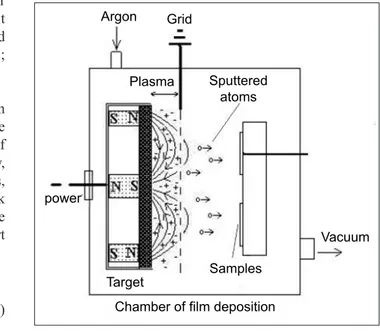
Titanium thin films were deposited on commercial polyethylene terephthalate (PET) substrates, with 0.1 mm of thickness, using the triode magnetron sputtering (TMS) technique, based on the TMS equipment presented by Fontana and Muzart (1998). The present process differs from the conventional magnetron sputtering, due to the presence of a screen parallel to the target, 2.0 cm from it. This screen is grounded and it improves the confinement of the plasma next to the target, thus providing greater stability and higher rate of ionization. This system makes it possible to work at low gas pressures (2.0 mTorr of argon). As a result, the atoms sputtered interact with the substrate without colliding with the gas atoms of the plasma atmosphere. Figure 1 shows a scheme of this system and Table 1 presents the experimental parameters used in the depositions.
!
Grid
Plasma
Vacuum
Chamber of film deposition Sputtered
atoms Argon
power
Target Samples
Experimental characterization
Relectivity measurements were taken in order to obtain the
attenuation values of the incident electromagnetic wave in
the titanium thin ilm. These measurements were obtained
in a vector network analyzer (8510, Hewlett-Packard, USA). The present experimental apparatus allows evaluating the
attenuation value of the metallic thin ilm stored on the
polymeric substrate in the frequency range of 8 to 12 GHz.
The waveguide technique involves a device made with high mechanical precision, where the propagation of electromagnetic wave occurs in a closed system (Nicholson and Ross, 1970). This system basically consists of a waveguide with one terminal to generate the microwave signal and another one to collect the
relected signal that is conducted for spectral analysis
(Nohara, 2003). Two different methodologies are used to measure the wave attenuation in this equipment. In
the irst, it is possible to measure the absorbed energy
(Ea) considering the difference between incident (Ei) and transmitted energies (Et). Figure 2a shows this condition schematically. This setup is similar to the RAM characterization in free space condition and it provides information about the intrinsically energy absorbed. In the second methodology, a metal plate
(Al plate) is located behind the thin ilm/substrate
set. In this case, it is evaluated the performance of the sample in the electromagnetic energy attenuation,
considering the thin ilm positioned on the metal plate.
The Ea is obtained by the difference between Ei and the
relected energy (Er). Figure 2b shows this apparatus schematically. This process simulates the absorber
material put on a relected surface, representing a
real situation, for example, the RAM application to aeronautical fuselage. Both methods, schematically presented in Fig. 2, were used to characterize the
prepared ilms.
Surface analyses of the films were performed by the scanning electron microscopy technique (SEM) using an equipment from LEO, model 435 VPI, and thin film samples without special preparation. Rutherford backscattering spectroscopy (RBS) (Bubert et al., 2002) was also employed to complete the surface characterization of the films. For this, a beam of He+ with energy of 2.2 MeV was used. The results were analysed by the RUMP software (Doolittle, 1985). Based on the SEM and RBS analyses the morphology and the thickness of the films were evaluated, respectively.
The thickness of the ilms was also evaluated by perilometry technique, using an equipment Dektak 3030, and thin ilm samples were deposited on silicon plates, simultaneously to the thin ilm deposition on PET substrate.
This methodology guarantees the same thickness for the
deposited ilms on two different substrates. The silicon
plate has an adhesive tape that is pull out from the silicon
substrate before the perilometry analysis, creating a step between the silicon substrate and the deposited ilm. This
step is measured by a tip moving on the sample.
The electric resistivity of the ilms was evaluated by a
four-point resistivity methodology using an equipment Veeco, model FPP5000. The electronic mobility was measured by the Hall effect technique using a Hall system produced by Bio-Rad Company, model HL5500.
Table 1. Experimental parameters used for the titanium thin ilm depositions.
Voltage (V)
Current (A)
Pressure
(mTorr) depositionTime of (s)
Thickness (nm)
-320 2.0 2.0 5-90 25-420
Figure 2. Waveguide settings used for the relectivity measurements of the titanium ilms: (a) evaluation of the intrinsic absorption; (b) relectivity with metallic plate (adapted from Nohara, 2003). Ea: absorbed energy; Er: relected energy; Ei: incident energy; Et: transmitted energy.
Waveguide (metallic)
sample Metallic thin film Ea
Er Ei Et Waveguide
(metallic)
Tottaly refletive
plate
sample Metallic thin film Ea
Er Ei
(a)
RESULTS AND DISCUSSION
The perfilometry measurements show that the titanium thin films were deposited at 3.6 nm/s on both polymeric and silicon substrates. This parameter, when determined by RBS analyses, shows values close to 5.0 nm/s. Besides the differences observed, these values present the same magnitude. However, considering that the RBS is a technique more precise, the thin film thickness values were calculated based on the deposition rate of 5.0 nm/s. The RBS analyses also show that the thin films are homogeneous, that is, without impurities. These results are attributed
to the adequate parameters used in the deposition process, how high the deposition rate and low pressure (vacuum) were during the process.
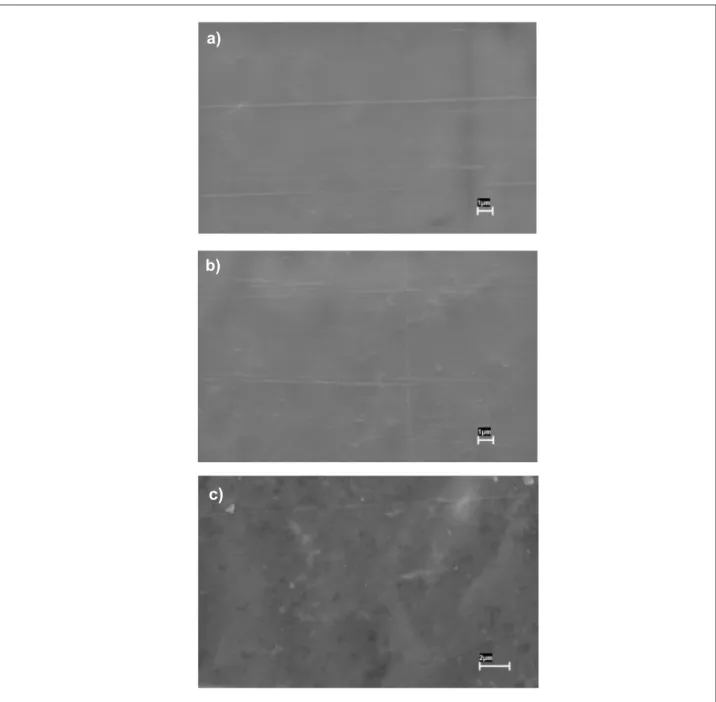
SEM analyses of titanium thin ilms with 25, 45 and
150 nm of thickness show similar morphologic aspects for
the analysed surfaces (Fig. 3). In the used magniication,
Fig. 3 shows surfaces with large uniformity, continuous structure, and absence of imperfections.
Figure 4 shows the average of the relectivity
measurements in the frequency range of 8 to 12 GHz
Figure 3. Scanning electron microscopy technique of titanium thin ilm with different thickness values: (a) 25 nm; (b) 45 nm, and (c) 150 nm.
a)
b)
Figure 4. Relationship between microwave attenuation and titanium thin ilm thickness.
0 100 200 300 400 500
0 20 40 60
Ti thin films deposited by TMS
Attenuation (%)
Thickness (nm)
Time of deposition
(s) Thickness x 10
9
(m)
Surface resistance
(Ω)
ρ x 106
(Ω.m)
δ x 105 (m)
(f=8 GHz) δ x 10
5 (m)
(f=12 GHz)
5±1 25±5 117 132 6.47 5.28
10±1 50±5 28.0 6.34 1.41 1.15
15±1 75±5 19.7 6.69 1.45 1.18
20±1 100±5 6.51 2.53 0.89 0.73
Table 2. Skin depth values of titanium thin ilms with different thicknesses.
Thickness (nm) Average absorption (%)
25±5 44.3
50±5 33.0
75±5 40.1
100±5 17.8
Table 3. Microwave absorption and thickness of titanium thin
ilms. Table 4. Electronic mobility of titanium thin ilms with different thicknesses.
Thickness (nm) Electronic mobility (µe) (cm2/V-s)
25±5 0.708
50±5 1.11
75±5 6.94
100±5 17.3
for the titanium thin ilms with different thicknesses.
These results were obtained by using the waveguide technique, according to schedule in Fig. 2b, which
shows that the slender ilm (25 nm) presents attenuation
values near 45% in the frequency range analysed
and thicker ilms (>100 nm) behave as less eficient
microwave absorbers.
The curve observed in Fig. 4 can be represented by a polynomial function, as shown in Eq. 2, where a and
b are constants, equals to 240.9 and -0.62, respectively. Based on such equation, it is possible to estimate that
titanium ilms with thickness values near 4.0 nm attenuate
nearby 100% of the incident electromagnetic wave. This behavior is explained by the increase of defects in the
crystalline structure of the nanoilm as the thickness decreases, which favors the losses in the metallic ilm,
as cited in the literature (Bosman, Lau and Gilgenbach, 2003; 2004; Shubin et al., 2000).
y=a.xb (2)
where:
y: represents attenuation (%);
x: represents thickness (nm) and
a and b: are constants (240.9 and -0.62, respectively).
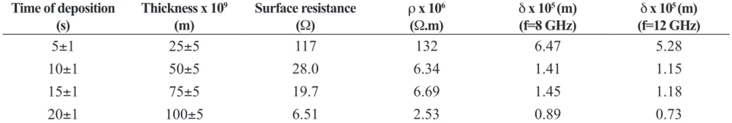
From the electric resistivity measurements of the
titanium thin ilms by using the four-point resistivity technique and the thickness of the ilms, the skin depth
parameters were calculated according to Eq. 1 for 8 and 12 GHz. The skin depth calculated, the electric resistivity (ρ), and the supericial resistance (R) are
presented in Table 2.
Table 2 shows that the electric resistivity decreases as the thickness increases. When correlating these
results with the curve in Fig. 3, it is veriied that
larger attenuation of electromagnetic wave energy
is associated with the thinner ilms. This behavior is
explained by the thickness increase to be related to the lower electric resistivity, which diminishes the losses
and consequently the attenuation. Thus, ilms with
smaller thickness provide more effective microwave absorbers, in agreement with Machlin (1998). This behavior is better observed in Table 3, which presents the thickness in function of the average absorption.
Table 2 also shows that the thickness of the ilms is
The electric behavior of the titanium thin ilms was
also evaluated by Hall effect technique. Table 4 shows
the electronic mobility of the studied ilms and it is
observed that this property increases as the thickness increases, meaning that the electron mobility is favored
in thicker ilms. This behavior suggests that thicker ilms begin to show the characteristics of the bulk metal, i.e., a relector material. For thinner ilms, the
electron mobility is diminished favoring the losses as heat by Joule effect, as mentioned by Nohara (2003).
These results show that titanium thin ilms behave more eficiently as microwave absorbers when there
is thickness around 25 nm. This behavior is associated
with the Eddy current formation on the ilm surface and
it is also the lowest electronic mobility that favors the losses.
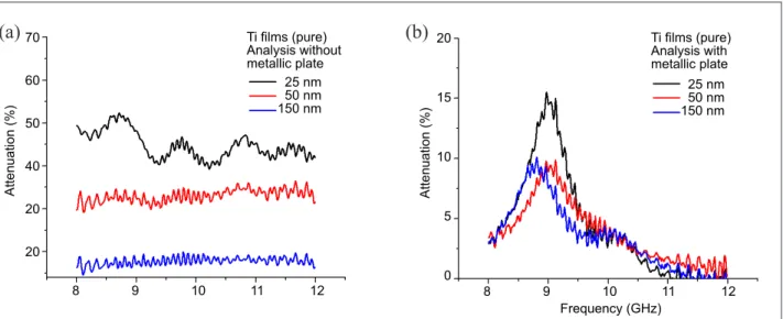
Figure 5 shows the relectivity measurements of the titanium thin ilms with different thicknesses, obtained
in different deposition times. The curves showed in Fig. 5a were obtained by using the setup depicted in Fig. 2a, while Fig. 4b presents the curves obtained in the setup showed in Fig. 2b. Figure 5a shows the
behavior of thin ilm with 25 nm, where absorption
values between 40 to 50% in all frequency range (8-12 GHz) are observed. Samples with larger thicknesses present lower absorption values, but nearly constant in all frequency range evaluated. Curves of samples prepared with thicknesses larger than 150 nm are not presented because they show similar behaviors, with absorption values between 5 and 10%.
Figure 5b presents the relectivity mesurements using an aluminum plate (100% relector) under the thin ilms
(setup in Fig. 2b). These curves show the maximum absorption value and the frequency where this event
occurs. These data conirm the dependence of microwave attenuation with the thin ilm thickness, and they also
present a slight variation of the maximum attenuation with the frequency (8.6-9.0 GHz), according to the thin
ilm thickness.
CONCLUSION
The TMS proved itself as a suitable technique to obtain
titanium thin ilms, which perform eficiently as RAM. Relectivity results from the waveguide technique (8-12 GHz) of the processed metallic thin ilms, with
thickness range from 25 to 100 nm, show microwave attenuation values around 50% in broadband (8-12 GHz). These attenuation results are attributed to the electric resistivity and electronic mobility of the titanium thin
ilms. The relectivity results show that the maximum attenuation value (around 50%) occurs for thinner ilms
(25 nm), which also present lower resistivity and electronic mobility that favor the losses.
ACKNOWLEDGMENTS
The authors acknowledge the inancial support of Fundação de Amparo à Pesquisa do Estado de São Paulo (FAPESP), process no. 05-01258-05; Financiadora de Estudos e
Projetos (FINEP), process no. 1757-03; and National
Counsel of Technological and Scientiic Development
(CNPq), processes no. 305478/2009-5 and 311396/2006-2; and also UDESC for providing the TMS equipment;
Laboratório de Materiais e Feixes Iônicos (LAMFI) for the RBS analyses; Laboratório de Sistemas Integráveis (LSI)
Figure 5. Attenuation curves of titanium thin ilms deposited at different times: (a) without metal plate (intrinsic absorption); (b) with metal plate (relectivity measurements).
Ti films (pure) Analysis without metallic plate
Ti films (pure) Analysis with metallic plate 70
60
50
40
20
20
20
15
10
5
0
Attenuation (%) Attenuation (%)
Frequency (GHz) 25 nm
50 nm 150 nm
25 nm 50 nm 150 nm
8 9 10 11 12 8 9 10 11 12
from USP/SP for the electric resistivity and perilometry
analyses; and Laboratório de Semicondutores (LabSem) of PUC/RJ for the Hall effect analyses.
REfERENCES
Balanis, C.A., 1989, “Antenna Theory: analysis and design”. John Wiley Sons, New York, USA.
Bhat, K.S., Datta, S.K. and Suresh, C., 1998, “Electrical and microwave characterization of kanthal thin
ilms: temperature and size effect”, Thin Solid Films,
Vol. 332, No. 1-2, pp. 220-224. doi:10.1016/S0040-6090(98)01103-1.
Biscaro, R.S., Rezende, M.C. and Faez, R., 2008,
“Inluence of doped polyaniline on the interaction
of Pu/PAni blends and on its microwave absorption properties”, Polymers for Advanced Technologies, Vol. 19, No. 2, pp.151-158. doi: 10.1002/pat.990.
Bosman, H., Lau, Y.Y., Gilgenbach, R.M., 2003, “Microwave Absorption in a Thin Film”, Applied Physics Letters, Vol. 82, No. 9, p.1353. doi:10.1063/1.1556969.
Bosman, H., Lau, Y.Y., Gilgenbach, R.M., 2004, “Power
absorption by thin ilms on microwave windows”,
IEEE Transactions on Plasma Science, Vol. 32, No. 3, pp. 1292-1297. doi:10.1109/TPS.2004.827579.
Bregar, V.B., 2004, “Advantages of Ferromagnetic Nanoparticle Composites in Microwave Absorbers”, IEEE Transactions on Magnetics, Vol. 40, No. 3, pp. 1679-1684. doi: 10.1109/TMAG.2004.826622.
Bubert, H., Jenett, H., 2002, “Surface and Thin ilm
Analysis”, Institute of Spectrochemistry and Applied Spectroscopy (ISAS), Wiley-VCH, Germany, 336p.
Doolittle, L.R., 1985, “Nuclear Instrument Method – Rump simulation code”, B9, pp. 344-351.
Folgueras, L.C., Rezende, M.C., 2007, “Hybrid multilayer structures for use as microwave absorbing material” Proceedings of the SBMO/IEEE MTT-S International Microwave & Optoelectronics Conference, Brazil, pp. 483-487.
Fontana, L.C., Muzart, J.L.R., 1998, “Characteristics of triode magnetron sputtering: the morphology of
deposited titanium ilms”, Surface and Coatings
Technology, Vol. 107, No. 1, pp. 24-30. doi:10.1016/ S0257-8972(98)00576-3.
Fortunato, E., Nunes, P., Costa, P.D., Brida, D., Ferreira, I. and Martins, R., 2002, “Characterization
of aluminium doped zinc oxide thin ilms deposited on
polymeric substrates”, Vacuum, Vol. 64, pp. 233-236. doi:10.1016/S0042-207X(01)00319-0.
Hashsish, E.A., 2002, “Design of wideband thin layer planar absorber”, Journal of Electromagnetic Waves and Applications, Vol. 16, No. 2, pp. 227-241. doi: 10.1109/APS.2011.5997137.
Ishii, N., Yasaka, Y., 2004, U.S.Patent No 6823816. Available at: www.patents.com/us-6823816.html.
Kaiser, K.L., 2004, “Electromagnetic Compatibility Handbook”, CRC Press, Boca Raton, USA.
Machlin, E.S., 1998, “Materials Science in Microelectronics”, Elsevier, 2a ed., New York, Vol. 2, pp. 1-70.
Mayes, E., 2006, U.S. Patent No 6986942. Available at: www.patents.com/us-6986942.html.
Mikhailovsky, L.K., 1999, “Solution of actual problems of electromagnetic compatibility by means of Spin (Non-Current) Electronics and Non-phase Electrodynamics”, Proceedings of the VIII International Conference on Spin Electronics – Section of International Conference on Gyromagnetic Electronics and Electrodynamics, Vol. 13-16, Moscow Region, Fisanovka, Rússia, pp. 327-349.
Nicolson, A. M., Ross, G. F., 1970, “Measurement of the Intrinsic Properties of Materials by Time Domain Techniques”, Instrumentantion and Measurement, Vol. 19, pp.377-382. doi: 10.1109/TIM.1970.4313932 .
Nie, Y., et al., 2007, “The electromagnetic characteristics and design of mechanically alloyed Fe-Co particles for electromagnetic-wave absorber”, Journal of Magnetism and magnetic materials, Vol. 310, pp.13-16. doi:10.1016/j.jmmm.2006.07.021
Nohara, E.L., 2003, “Materiais Absorvedores de Radiação Eletromagnética (8-12 GHz) Obtidos pela Combinação de Compósitos Avançados Dielétricos e Revestimentos Magnéticos”. Ph.D. Thesis, Technological Institute of Aeronautics, São José dos Campos, S.P., Brazil.
Rezende, M.C., Silva, F.S. and Martin, I.M., 2000, “Materiais absorvedores de radiação eletromagnética”, Spectrum, Vol. 2, pp. 17-20.
Salmon, L.G., 1993, “Evaluation of thin ilm MCM
materials for high-speed applications”, IEEE Transactions on Components, Hybrids, and Manufacturing Technology, Vol. 16, No. 4, pp. 388-391. doi: 10.1109/33.237934.
Serway, R.A., 1998, “Principles of Physics”, Saunders College Texas, Fort Worth, London.
Shubin, V.A., et al., 2000, “Local electric and
magnetic ields in semicontinuous metal ilms: beyond