BLASTNIMO PERFORMANCE WITH SPACE-TIME PROCESSING RECEIVERS
zyxwvutsrqponmlkjihgfedcbaZYXWVUTSRQPONMLKJIHGFEDCBA
F. R. P. Cavalcanti, A. L. F. de Almeida, C. E. R. Femandes and W. C. Freitas Jr.GTEL-UFC: Wireless Telecom Research Group, Federal University of Ceara, Fortaleza, Brazil
zyxwvutsrqponmlkjihgfedcbaZYXWVUTSRQPONMLKJIHGFEDCBA
U RL:www.gtel.ufc .br
zyxwvutsrqponmlkjihgfedcbaZYXWVUTSRQPONMLKJIHGFEDCBA
{ rod,andre,estevao,wal ter} @gtel.ufc. br Abstract
-
The use of antenna arrays at both ends of thelink has attracted significant attention of the researches on space-time equalization and coding techniques for so called multiple-input-multiple-output (MIMO) channels. The pres- ence of strong co-channel interference (CCI) in addition to inter-symbol interference (1S1) in current wireless (mo- bile) communication systems places a significant challenge
to MlMO space-time equalizers. In
zyxwvutsrqponmlkjihgfedcbaZYXWVUTSRQPONMLKJIHGFEDCBA
this work we assess per-formance of BLAST/MIMO on frequency-selective MlMO channel model in the presence of CC1. Space-time process- ing is used in order to deal with the fiequency selectivity and to provide more degrees of freedom to deal with co- channel interference. We consider two non-linear space-time processing-based receivers. The first one is a MlMO space- time decision feedback equalizer (MIMO ST-DFE) and the second one is a space-time delayed decision feedback se- quence estimator (MIMO ST-DDFSE) with actual adaptive algorithms for channel acquisition. Noise-limited as well as interference-limited situations are evaluated
Keywords
-
BLAST, space-time processing, MIMO, equal- ization, kequency selectivity and co-channel interference1.
INTRODUCTION
Recently, very high spectral efficiencies and unprecedented data rates achieved on a wireless environment have been demonstrated to be practical when both the transmitter and receiver employ multiple antennas [ 1-51. With rich multipath propagation and appropriate signal processing at the receiver side, these sub-streams can be separated so that the wireless channel can be viewed at the receiver as virtual parallel inde- pendent space-time channels.
As in the BLAST architecture, the use of antenna arrays at
both ends of the
zyxwvutsrqponmlkjihgfedcbaZYXWVUTSRQPONMLKJIHGFEDCBA
link
has attracted sigrulkant attention of theresearches on space-time equalization and coding techniques for so called multiple-input-multiple-output (MIMO) chan- nels. The presence of strong co-channel interference (CCI) in addition to inter-symbol interference (1S1) in current wireless (mobile) communication systems places a significant chal- lenge to MlMO space-time equalizers. Most of works con- cerning the performance of BLAST/MIMO system assume the availability of perfect channel state information at the re- ceiver or at both transmitter and receiver. Moreover, usu- ally, the MlMO channel is modeled as a matrix of indepen- dent complex Gaussian gains underlying the assumption of
flat (narrowband) fading and a high degree of spatial diversity available on the propagation environment. Recently, the per- formances of different receiver structures on BLAST/MlMO systems on fiequency selective wireless channels have been evaluated by several authors [6,7]. However, all these works have not considered the presence of co-channel interference, which may not be realistic in mobile communication systems.
In this work we assess performance of BLAST/MIMO on fiequency-selective MlMO channel model in the presence of CCI. Space-time processing is used in order to deal with the fiequency selectivity and to provide more degrees of freedom to deal with co-channel interference. We consider two non- linear space-time processing-based receivers. The fmt one is a MlMO space-time decision feedback equalizer (MIMO ST-DFE) and the second one is a space-time delayed decision feedback sequence estimator [8] (MIMO ST-DDFSE) where actual adaptive algorithms are used for channel acquisition. Noise-limited as well as interference-limited situations are evaluated.
This paper also discusses the range of achievable data rates under the physical layer h e w o r k of the EDGE (Enhanced Data Rates for Global Evolution) 3rd generation air interface when employing such techniques. BLAST/MIMO architec- tures can be viewed as an option for future upgrades of exist-
ing and proposed
zyxwvutsrqponmlkjihgfedcbaZYXWVUTSRQPONMLKJIHGFEDCBA
2.5G and 3G air interfaces in the pursuit ofhigher data rates.
The focus of the paper is on relatively low complexity space-time detection structures. Essentially only linear space- time processing is employed but separate temporal processing is allowed to employ non-linear techniques such as decision- feedback and maximum likelihood sequence detection. While optimum MlMO detection is based on vedor-Viterbi stmc- tures, their complexity is prohibitive for the type of modula- tion and channel dispersion typical in currently existing and proposed wireless systems.
This paper is organized as follows. Channel and system- model is established on Section 11. The MlMO ST-DFE and MlMO ST-DDFE receiver structures for data detection are illustrated in section 111. Section 1V discusses the ap- plication of BLAST/MlMO architectures on the context of EDGE/EGPRS system. Section V presents the simulation re-
Multipath Fading:
I
-cuc5mme(hwkmlD3
zyxwvutsrqponmlkjihgfedcbaZYXWVUTSRQPONMLKJIHGFEDCBA
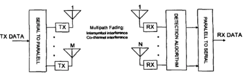
Fig. 1. Multiple Transmit-Receive Antenna Communications Architecture.
zyxwvutsrqponmlkjihgfedcbaZYXWVUTSRQPONMLKJIHGFEDCBA
11. CHANNEL AND SYSTEM MODELS A high-level system block diagram is shown in Fig. 1 in its equivalent baseband model, concerning a single-user link. All transmitters (1 to M) operate co-channel at the same sym- bol rate with synchronized symbol timing. The transmission procedure is simple: transmission data is split into M sub- streams and independently transmitted by transmit antennas
1 to M. The
zyxwvutsrqponmlkjihgfedcbaZYXWVUTSRQPONMLKJIHGFEDCBA
total transmitted power is k e d and normalizedto 1. For simplicity we assume all transmitters operating with
the same
zyxwvutsrqponmlkjihgfedcbaZYXWVUTSRQPONMLKJIHGFEDCBA
8-PSK modulation.In
the receiver side, an antenna array of NzyxwvutsrqponmlkjihgfedcbaZYXWVUTSRQPONMLKJIHGFEDCBA
2
M anten-nas is connected to a bank of
zyxwvutsrqponmlkjihgfedcbaZYXWVUTSRQPONMLKJIHGFEDCBA
hl space-time equalizers, forthe recovery of each data sub-stream. After detection, the data sub-streams are re-ordered and converted to the serial unique stream that constitutes the estimated transmitted data. We assume symbol-rate sampling and perfect synchronization among all receivers. Furthermore, the fading in the channel is assumed to be quasi-static over every sub-stream of data and it is independent between the transmission of each set of sub-streams. We can represent the discrete-time channel im- pulse response &om the transmit antenna m to the receiving
antenna n as follows:
where L
+
1 is the number of taps in the channel impulse re- sponse. The channel "seen" by the N-element antenna array &om the transmit antenna m is obtained by arranging into an channel matrix,
so that the received signal vector is expressedas:
zyxwvutsrqponmlkjihgfedcbaZYXWVUTSRQPONMLKJIHGFEDCBA
Af
m = 1
zyxwvutsrqponmlkjihgfedcbaZYXWVUTSRQPONMLKJIHGFEDCBA
x(k) = Hmam(k) + v ( k ) (2)
where aTn(k) = [a,,(k)
zyxwvutsrqponmlkjihgfedcbaZYXWVUTSRQPONMLKJIHGFEDCBA
a,n(k - 1). . .
a,,(k - L)] is anL
+
1 vector representing the symbol sequence transmitted by the mth antenna. The power of each transmitted sub-stream is equal to5 ,
where P is the total average transmitted power. Finally, the vector denotes the temporally and spatially ad- ditive white Gaussian noise (AWGN). Considering pure spa- tial processing at the receiver, the output signal is denoted byy T n ( k ) = w,a(k), where w, = [wrnl w7n2
. .
-
W,N] is the array weight vector for the mth transmit antenna.111. SPACE-TIME RECEIVERS
A . MIMO ST-DFE
The MIMO space-time decision feedback equalizer, called here MlMO ST-DFE, is shown in Fig. 2 [9,6]. It consists of a bank of M linear space-time feedfoward filters of N branches and F
+
1 taps per branch, followed by hl multiple-input- single-output (MISO) feedback filters of B taps. The MlMO ST-DFE may be considered as an extension of the narrow- band V-BLAST concept [2] to the case of frequency selec- tive channels if the ordered successive interference cancelling technique is employed. However, we work here with a sim- plified approach, a "parallel" detection, so that all the M sub- streams are detected simultaneously. The parallel detection is a simplified approach where no mechanism of detection or- dering is applied. This approach is therefore less complex and induces no detection delay when compared to the successive technique. All the sub-streams id,n ( k-
d) are detected simul- taneously, where d is the training delay. The comparison of the performance of an ordered detection MlMO space-time equalizer with the current approach are left to a fbture work.B. MIMO ST-DDFSE
Figure 3 illustrates the employed MlMO ST-DDFSE struc- ture. Ideally in terms of optimum MlMO detection, a vec- tor DDFSE equalizer should be used to perform sequence estimation. A vector DDFSE (V-DDFSE) involves a vec- tor Viterbi algorithm sequence estimator of memory 11 and a MlMO feedback scheme of memory B
-
11. Note that when11 = 0, a MlMO ST-DDFSE reduces to the MlMO ST-DFE of the last paragraph. On the other hand, if 11 = B, it becomes a full state vector Viterbi detector. The complexity of the MlMO ST-DDFSE also grows exponentially with the num- ber of transmit antennas M. Thus, another free parameter to control the complexity of this algorithm, and a consequently Compromise between 11 and M should be taken into account.
In this work, looking into low complexity schemes, we deal with a simplified approach by employing M parallel and independent ST-DDFSEs
.
By "independent" we meanFig. 2. MlMO ST-DFE structure.
zyxwvutsrqponmlkjihgfedcbaZYXWVUTSRQPONMLKJIHGFEDCBA
M x
zyxwvutsrqponmlkjihgfedcbaZYXWVUTSRQPONMLKJIHGFEDCBA
zyxwvutsrqponmlkjihgfedcbaZYXWVUTSRQPONMLKJIHGFEDCBA
DDFSEzyxwvutsrqponmlkjihgfedcbaZYXWVUTSRQPONMLKJIHGFEDCBA
,... ...
j
zyxwvutsrqponmlkjihgfedcbaZYXWVUTSRQPONMLKJIHGFEDCBA
i , ( k - d )
nulrr
V l m b
i ... I... : ..
... :
q k - d )
zyxwvutsrqponmlkjihgfedcbaZYXWVUTSRQPONMLKJIHGFEDCBA
d u
b
L. ...
- :
...
Fig. 3. MlMO ST-DDFSE structure.
sub-streams, resulting in a single-user scalar Viterbi algo- rithm. lmproved performance is expected if we use a vector Viterbi, but complexity would be quite high even for a mod- erate number of transmit antennas and considering the 8-PSK modulation assumed. Presented originally in [SI, the DDFSE strategy has been the focus of several recent studies [ 10- 121
concerning the equalizer design for the EDGE
zyxwvutsrqponmlkjihgfedcbaZYXWVUTSRQPONMLKJIHGFEDCBA
air interface.Due to modulation and symbol-rate employed in EDGE, op timum MLSE temporal equalization becomes impractical and
this type of reduced-complexity detection scheme should be
considered. The DDFSE is a promising candidate due its good performancecomplexity tradeoff.
1V. APPLICATION ON THE EDGE/EGPRS CONTEXT The physical layer model used for simulations of the next section is inspired on the EDGE (Enhanced Data Rates for Global Evolution) air interface [13, 141. Except for the pulse shaping, which is assumed here as 35% raised cosine, all other features of the EDGE physical-layer at the time-slot level are assumed (e.g. 8 PSK modulation). A brief dis- cussion on how BLAST/MlMO architectures could be used
Fig. 4.
for downlink transmission on the EDGE air interface. Possible MlMO system (transmission) architecture
to improve the performance of the EDGE air interface now takes place.
The use of BLAST/MlMO architectures could reduce the time of transmission of a radio link control (RLC) block in the physical layer of EDGE. In its traditional form, a RLC block that corresponds to 4 frames, is transmitted in about 2Oms, taking into account the idle frames. The use of BLAST/MlMO can reduce this time by a factor of four when four antennas are used in transmission. For example, in MCS-7 a block containing 896 bits is transmitted in four con- secutive fiames that corresponds to 20ms, so the maximum throughput achieved is 896 bits/20ms = 44.8Kbps. As an ex- ample, if a BLAST/MlMO architecture with 4 transmit an- tennas is used, the same RLC radio block is transmitted now in about 5ms. The throughput is increased by a factor of four respectively, achieving a new throughput of 179.2 Kbps, re-
spectively. The system architecture for two transmit antennas is shown in Fig. 4.
V. SIMULATION RESULTS
Simulations are either noise or interference-limited. Down-
link is considered, so that the angle spread is assumed to be 360". This is reasonable, since local scattering around the mobile station leads to large angle spread values. For the noise-limited case, the bit energy-to-noise spectral density ra- tio (Eb/No) is fixed on the value perceived by most connec-
tions in a typical EDGE link-budget [l 51, e.g. 18
ds.
For the interference-limited case, a single co-channel source with a signal-to-interference ratio (SIR) of 10 dB is assumed. Both the desired user and the co-channel interferer channels are frequency-selective, following the typical urban (TU)GSM
channel profile [ 151. Our benchmark for comparison is the case of flat Rayleigh faded channels with pure spatial pro- cessing.transmit (Tx) antennas, varying the number of receive (Rx)
antennas N fiom 3 up to 6. The space-time feedfoward filters have 2 taps per Rx antenna and we employ 2 feedback taps in both MlMO ST-DFE and MlMO ST-DDFSE. The feedback
scheme of MlMO ST-DDFSE are characterized by
zyxwvutsrqponmlkjihgfedcbaZYXWVUTSRQPONMLKJIHGFEDCBA
pzyxwvutsrqponmlkjihgfedcbaZYXWVUTSRQPONMLKJIHGFEDCBA
= 1,i.e., the MLSE portion of DDFSE has 8 states. Higher values
of would not increase performance significantly,
zyxwvutsrqponmlkjihgfedcbaZYXWVUTSRQPONMLKJIHGFEDCBA
at the costof a higher complexity [ 1 13. All the above-related parameters are the same for all M.
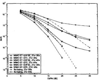
In Fig. 5 we present the BER as a function of Eb/No
on TU profile, in the absence of CCI. Considering the same
zyxwvutsrqponmlkjihgfedcbaZYXWVUTSRQPONMLKJIHGFEDCBA
M and N, the MlMO ST-DFE has the best performance on
all antenna configurations. This is reasonable, since MlMO ST-DDFSE ignores the interference between the transmit- ted sub-streams. Note that the two equalization strategies present similar results if we employ an additional Rx antenna for the MlMO ST-DDFSE case. In terms of receiver com- plexity, if we used the vector DDFSE the number of states (NS) would increase exponentially with M. As an exam- ple, for 8-PSK modulation and working with 2Tx-3Rx con- figuration, NS = 64 states per Rx antenna, which gives a
total of NS =
zyxwvutsrqponmlkjihgfedcbaZYXWVUTSRQPONMLKJIHGFEDCBA
M xzyxwvutsrqponmlkjihgfedcbaZYXWVUTSRQPONMLKJIHGFEDCBA
64 = 192 states. By using the pro-posed approach (scalar DDFSE) with one additional Rx an- tenna, NS = 8 states per Rx antenna, resulting in a total of
NS = N x 8 = 32 states. Even with two more receive anten- nas (2Tx-5Tx configuration), NS = 40 states. In this case the MlMO ST-DDFE outperforms MlMO ST-DFE, as shown in Fig. 5.
Observe that, in the scalar DDFSE approach, the complex- ity does not depend on the number of Tx antennas, and grows
linearly with the number of Rx antennas
zyxwvutsrqponmlkjihgfedcbaZYXWVUTSRQPONMLKJIHGFEDCBA
N.
Furthermore, forincreased values of M, the MlMO ST-DFE may degrade its performance due to the large number of equalizer coefficients
to be adapted, ( M times the number
zyxwvutsrqponmlkjihgfedcbaZYXWVUTSRQPONMLKJIHGFEDCBA
of coefficients of MlMOST-DDFSE). These results justify our preliminary choice of a scalar DDFSE scheme for BLAST/MlMO systems. The per- formance on flat Rayleigh fading channel (narrowband case) with pure spatial processing is plotted as a benchmark for comparison.
We now consider the presence of CCI. From Fig.6 it can be seen that the MlMO ST-DFE with 2TX-4Rx outperforms the
MlMO
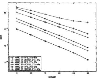
ST-DDFSE with the same antenna configuration. Comparing Figs. 5 and 6 we verify that, for a target uncoded BER of the Eb/No loss of MlMO ST-DFE due to CCI is about 4 dB with 2Tx-5Rx configuration. This loss is almost 13 dB with MlMO ST-DDFSE and the same antenna config- uration. Concerning the performance comparisons between the two equalization strategies, the same comments done for Fig. 5 are also valid for Fig. 6.Concerning the noise-limited results, we present in Fig. 7 the bit-error-rate (BER) as a function of the input SIR for a k e d Eb/No=18 dB. Observe that the BER decreases almost linearly with Eb/No with an increasing SIR. The MIMO ST- DDFSE tends to exhibit a BER floor for the 2Tx4Rx con- figuration. For a target uncoded BER of lo-', the
SIR
g a b4- MlMO ST-DDFSE. 2Tr3Rx
4 MlMO ST-DDFSE. ZTx-4Rx
-6- MIMOST-DFE. 2Tx4Rx
4-MIMOST-DDFSE. 2 T x - m
8 MlMO ST-DE. ZTX-51b: \ +
0 5 10 15 20 25 30
EWNO (m)
Fig. 5. Performance results of MlMO ST-DFE and MlMO ST-DDFSE on TU profile in the absence of CCI, for different antenna configurations.
t
Fig. 6. Performance results of MlMO ST-DFE and MlMO ST-DDFSE on TU profile with CCI, for different antenna con- figurations. (SIR=lOdB, 1 co-channel interferer)
of MlMO ST-DFE compared to MlMO ST-DDFSE is nearly 7
dB
for the 2Tx-4Rx and 2Tx-5Rx configurations. We alsoverify that the MlMO ST-DDFSE with one additional Rx an- tenna provides SIR gains between 2-4dB compared to MlMO ST-DFE.
VI.
CONCLUSION AND PERSPECTIVESIn this work, we have evaluated the performance of
-+
zyxwvutsrqponmlkjihgfedcbaZYXWVUTSRQPONMLKJIHGFEDCBA
MlMO ST-DDFSE. ZTx-4XzyxwvutsrqponmlkjihgfedcbaZYXWVUTSRQPONMLKJIHGFEDCBA
.+3- MlMO ST-DDFSE 2TX-Sfb;
10
zyxwvutsrqponmlkjihgfedcbaZYXWVUTSRQPONMLKJIHGFEDCBA
15zyxwvutsrqponmlkjihgfedcbaZYXWVUTSRQPONMLKJIHGFEDCBA
m 25 30SIR (a)
zyxwvutsrqponmlkjihgfedcbaZYXWVUTSRQPONMLKJIHGFEDCBA
Fig. 7. Performance results of MlMO ST-DFE and MlMO ST-DDFSE for a noise-limited scenario, TU profile, as a func- tion of the input
SIR,
for different antenna configurations.cases were considered. For the same number of
Rx
anten- nas, the MlMO ST-DFE outperformed the MlMO ST-DDFSE with scalar Viterbi detection, in all antenna configurations. The performance of MlMO ST-DDFSE with one more Rx an-tenna has showed to be equivalent to that of MlMO ST-DFE. The proposed MlMO ST-DDFSE, with scalar DDFSE detec- tors, may constitute a reducecomplexity detection scheme for EDGE, if BLAST/MIMO architecture is deployed. On TU prosle with CCI, the MlMO ST-DDFSE has presented sat- isfactory results with low complexity, compared to the vec- tor DDFSE case. The use of this type of multiple antenna technique can potentially provide an M-fold capacity gain in
terms of channel bit rate when
zyxwvutsrqponmlkjihgfedcbaZYXWVUTSRQPONMLKJIHGFEDCBA
M transmit antennas are used.This is interesting when viewed in the context of the evolu- tion of currently proposed 3G systems, such as EDGE, in the direction of higher data rates.
ACKNOWLEDGEMENTS
This work is supported by the Ericsson Research
-
Brazil-ian Branch under the ERBB/UFC.Ol Technical Cooperation Contract.
REFERENCES
[l] G. J.
zyxwvutsrqponmlkjihgfedcbaZYXWVUTSRQPONMLKJIHGFEDCBA
Foschini, ”Layered Space-Time Architecture forWireless Communications in a Fading Environment when
using Multiple Antennas”,
zyxwvutsrqponmlkjihgfedcbaZYXWVUTSRQPONMLKJIHGFEDCBA
Bell Labs Tech. J., v.1, n.2,[2] G. D. Golden, G.J. Foschini, RA. Valenzuela, P.W. Wol- niansky, ”Detection Algorithm and Initial Laboratory Re- sults using the V-BLAST Space-Time Communications Architecture”, Electronics Letters, v.35, n.7, Jan., 1999,
1996, pp.41-59.
pp. 14-15.
[3] T. L. Marzetta, B. M. Hochwald, ”Capacity of a Mobile Multiple-Antenna Communication
Link
in Rayleigh Flat Fading”, LEEE Trans. Info. Theory, v.45, n.1, Jan. 1999,[4] G. J. Foschini and M. J. Gans, ”On Limits of Wireless Communications in a Fading Environment When Using Multiple Antennas”, Wireless Personal Communications, v. 6,n. 3, March 1998,pp. 311-335.
[SI M. Martoni, Multiantenna, ”Digital Zkunsmission”, Artech House, 2002.
[6] A. Lozano, C. Papadias, ”Layered space-time receivers for fkequency-selective wireless channels”, Mh’E Ilkuns. Comm., pp. 65 -73, January, 2002.
[7] X. Zhu, R. Murch, ”Layered space-time equalization of
multiple-input multiple-output frequency-selective chan- nels”, IEEE International Conference on Communica-
tions, 1CC 2002,2002.
[8] A. Duel-Hallen, C. Heegard, ”Delayed Decision- Feedback Sequence Estimation”, IEEE Trans. Comm., pp. 428-436, May, 1989.
91
A. M. Tehrani, B. Hassibi, J. M. Cioffi, ”Adaptive Equal- ization of multiple-input multiple output (MIMO) chan- nels”, lEEE International Conference on Communica-tions, ICC 2000,2000.
101
S.
L. Ariyavisitakul, J. H. Winters, N. R. Sollenberger, ”Joint equalization and interference suppression forhigh
data rate wireless systems”, IEEE Journal Selec. Areas
Commun., pp. 1214-1220, July 2000.
111 W. H. Gerstacker, R. Schober, ”Equalization Concepts for EDGE”, IEEE Zkans. Wireless Comm., pp. 190-199 , Jan, 2002.
121 A. L. F. de Almeida, C. M. Panazio, E R. P. Cavalcanti, C. E. R. Fernandes, ”Space-Time Processing with a De- coupled Delayed Decision-Feddback Sequence Estima- tor”, LEEE Vehicular Technology Conference, Spring’O2, 2002.
[13] ETSl TS 100 573, ”Digital Cellular Telecommunica-
tions system (Phase 2+); Physical layer on the radio path; General description.”
[14] ETSl EN 300 959, ”Digital Cellular Telecommunica-
tions System (Phase 2 9 ; Modulation.”
[15] ETSl TS 100 910, ”Digital Cellular Telecommunica- tions System (Phase 2 9 ; Radio Transmission and Re-
ception. ”
[16] S . Haykin, ”Adaptive Filter Theory”, 3rd Ed., Prentice Hall, 1996.