BER Analysis of DFE-LMS Algorithm for
Smart Antenna System
Debendra Kumar Panda and SaimaShaikh Department of Electronics and Communication,
Medicaps Institute of Technology and Management, Indore, India e-mail:[email protected], [email protected]
Abstract—The “Smart” part of smart antenna system is the weight adjustment factor. The adaptive algorithms are used in smart antenna in order to adjust the weight of antenna arrays in a way that a main lobe is formed in the direction of desired user and nulls are formed in the direction of undesired user. In this piece of work we have done a comparative analysis of Least Mean Square (LMS) and Decision Feedback Equalizer based Least Mean Square (DFE-LMS) adaptive algorithms on the basis of Signal to Noise Ratio (SNR) and Bit Error Rate (BER). The simulation results observe the graph between SNR and BER on varying the number of iterations as well as modulation index. Implementation is done with the help of Matlab. The result shows that DFE-LMS algorithm has better performance than LMS.
Keyword-Antenna Arrays, Adaptive Algorithms, Beam-forming, Interference, Smart antenna, DFE-LMS,
LMS, SNR, and BER.
I. INTRODUCTION
The wireless technology is a great breakthrough in the field of communication. The demand for services like multimedia, data, voice etc. is increasing every single day without a corresponding increase in frequency spectrum allocation. There is a need to find certain techniques which will be able to fulfil these requirements. One of the techniques for better spectrum efficiency in digital cellular communication is the use of code division multiple access (CDMA) [1].CDMA had offered a high capacity but the expected demand likely to outstrip the projected capacity so the only option for substantial capacity enhancement is the use of spatial processing with smart antenna array. Using smart antenna technology, we could form multiple antenna beam to follow each user like spatial division multiple access (SDMA).Smart antenna systems employing multiple antennas provide for increased system capacity, extended radio coverage and improved quality of service through the ability to steer the antenna pattern in the direction of desired user while placing nulls at interferer locations [2].
Beamforming is the process of performing spatial filtering, the main objective of spatial filtering is to make a beam sensitive towards the desire target and null or attenuation towards directions of interfering signals or undesired target. There are various methods of implementation of beamforming techniques in time and frequency domain which depends on the speed of processing and the type of signals to be processed [3]. The beamformers can be categorized as time beamformers and frequency beamformers. Beamformers adjust the weight of different antennas with the help of different adaptive beamforming algorithms. The beamforming algorithms multiply the signal with the weight vector in-order to form to a beam pattern that radiates maximum power in the direction of desired target and forms side lobes or interferers in the direction of undesired target. Several different types of algorithm are used for beamforming of smart antennas. A comparative study has been done by the author between Least Mean Square (LMS) and Decision Feedback Equalizer based Least Mean Square (DFE-LMS) adaptive beamforming algorithms for smart antenna system. The author already compared both the algorithm in terms of convergence, mean square error, phase, amplitude and power [4-5]. In this paper the performance of beamforming algorithms are analysed on the basis of SNR vs. BER with varied number of iteration and different modulation index.
II. BEAMFORMING TECHNIQUE
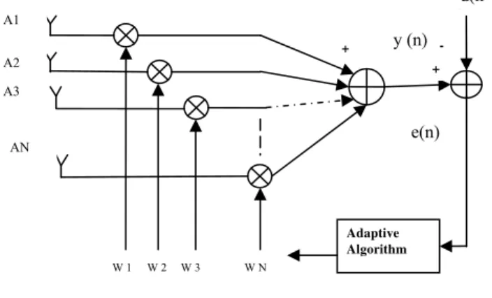
Beamforming is a process of adapting magnitude and phase of the signal from every antenna element by the use of product of each user’s signal and weight vectors [6].Beamforming is an advanced signal processing technique which, when employed along with an array of transmitters or receivers, is capable of controlling the 'directionality of' or 'sensitivity to' a particular radiation pattern [7]. An adaptive beam forming network is shown in Fig.1, the beam response for a given N-by-1weight vector W(n) is function of angle θ. This angular response is computed for all possible angle, that is 9 ° 9 °
R θ W n S θ
Where, S (θ) is an N-by-1 steering vector.
The dependence of the steering vector on θ is defined with the use of the relationship
Let φ denote the actual angle of incidence of a plane wave, measured with respect to the normal to the linear array then
θ πdsinφ, π θ π
Where d is the spacing between adjacent antennas of the array and λ is the wave length of the incident wave.
Fig. 1. Adapitve Beamforming network
The number of bit errors is the number of receiving bits of a signal data over a communication channel that has been changed because of noise, distortion, bit synchronization or interference [8].
Noise is the major factor which affects the performance of BER. SNR and BER are inversely proportional to each other. SNR is an indicator usually measures the clarity of the signal in a circuit or wireless transmission channel. SNR is given as the ratio between wanted signal and unwanted noise.
SNR PP
In terms of diversity SNR can be given as
BER
III.ADAPTIVE ALGORITHMS FOR SMART ANTENNA SYSTEM
The adaptive beamforming algorithms are used for updating and optimizing the weights of the received signal. The optimization is based on a particular criterion, which minimizes the contribution from noise and interference while producing the maximum beam gain at the desired direction [8].The two major types of adaptive algorithms are blind and non-blind. Non-blind algorithms require a pilot signal to detect the desired signal and update the complex weights. These algorithms include LMS, RLS, SMI and CGM. In contrast to non-blind algorithms, blind algorithms do notneed a pilot signal to find the complex weights. Blind algorithms include CMA, Spectral Self-Coherence Restoral (SCORE) and Decision Directed algorithm (DD) [9]. In this paper we discussed two non-blind algorithms, Least Mean Square and Decision Feedback Equalizer based Least Mean Square and analyses them for improved performance of smart antenna.
(a) Least Mean Square Algorithm
It is a stochastic gradient optimization algorithm based on a traditional optimization technique called the Method of Steepest Descent [9]. Let us define the input vector as
X x n , x n , … … . , x n N (1) And the vector of the weight coefficients as
W n w n w n w n … w n of adaptive filter at an instant n. N is the order of the adaptive FIR filter.
The signal samples at the equalizer input are of the form;
x n hn j a n j noise n
Where a (n) = nth data transmitted sample noise (n)=additive noise with variance hn(j)=channel impulse response
Adaptive Algorithm
W 1 W 2 W 3 W N
A1
A2
AN
d(n ) y (n)
e(n) -+ +
The equalizer output at the n-th iteration instant is:
y n W n X n (2)
The output y(n) is used in estimating the transmitted data symbol a(n-D), with D denoting to the delay The output error at the n-th iteration instant is
e n y n a n D (3)
The weighting coefficient in the linear LMS is obtained from;
W n W n e n x n (4)
Where µ is the algorithm fixed step size
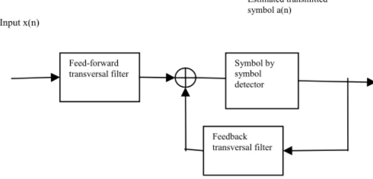
(b) Decision feedback equalizer Least Mean Square (DFE-LMS)
In Fig.2 there is a general structure of the adaptive decision feedback equalizer. This figure shows that DFE consists of two sections, feed-forward section and feedback section connected together [4]. The feedback section consists of a tap delay line filter (FIR type) whose taps are spaced at the reciprocal of the signaling rate [5]. The function of the feedback section is to subtract out that portion of the inter-symbol interference produced by previously detected symbols form the estimates of the future samples.
Upon convergence to optimum coefficients, the system is switched to a decision directed mode where the decisions at the output of the detector are used in forming the error signal and fed back to the feedback filter. This is the adaptive mode of DFE [5]
Fig. 2. Decision feedback structure
The updated equation for feed –forward filter is;
w n w n y n e∗ n (5)
The updated equation of feed-back filter is;
b n b n y n e∗ n (6)
The DFE-LMS is said to have faster convergence and less mean square error [5]. Inter-symbol interference is a major problem encountered in communication network and DFE LMS removes inter-symbol interference to large extent. Where
y [n] = Input at feed-forward filter at time n w [n] = current coefficient of feed-forward filter w [n+1] = updated coefficient of feed-forward filter b[n] = current coefficient of feedback filter b [n+1] = updated coefficient of feedback filter.
IV.SIMULATION RESULTS
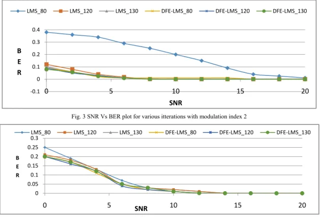
In the simulation, the smart antenna of 5 elements with uniform array and a linear channel is taken. The desired angle of signal is taken as π/3. The value of learning parameter is fixed as 0.01.The number of iteration is varied and the modulation index is taken as 2 and 4. The BER and SNR ratio is calculated according to the above simulation parameters.
Fig.3 shows the plot of SNR vs BER when modulation index is 2 with different number of iterations. It is observed that the BER of DFE-LMS becomes 0 when SNR is near about 7 whereas LMS does not for the no of iterations equals to 80. It is observed that LMS performance is improving when number of iteration is going to be increased. Fig.4 shows the plot of SNR vs BER when modulation index is 4 for various number of iterations. The BER vs SNR performance of LMS and DFE-LMS is becoming same but at the cost of increased modulation index.
Feed-forward transversal filter
Feedback transversal filter
Symbol by symbol detector Input x(n)
Fig. 3 SNR Vs BER plot for various itterations with modulation index 2
Fig. 4 SNR Vs BER plot for various itterations with modulation index 4
V. CONCLUSION
Smart antenna is a dynamic technology in the field of wireless communication. It had not only played a vital role in 3G, 4G mobile communications but also predicted to be helpful in introducing 5G technology. The performance of smart antenna system is optimized with the help of adaptive beamforming algorithms. In this work the performance of adaptive algorithms, Least Mean Square (LMS) and Decision feedback based Least Mean Square (LMS) is analysed on the basis of bit error and signal to noise ratio. It is observed that DFE-LMS gives better results for less number of iterations. DFE-LMS results can be matched to DFE-DFE-LMS but on the cost of increased number of iterations and modulation index. Thus it is concluded that DFE-LMS gives minimum bit error at lower value of signal to noise ratio and in less number of iterations and modulation index.
REFERENCES
[1] AnindyaKundu, Susanta Kumar Parui, “Capacity Improvement with Smart Antenna of TDSCDMA Base Station” International Journal of Advanced Research in Electrical, Electronics and Instrumentation Engineering, Vol. 3,Issue 4,pp.9063-9071, April 2014.
[2] M Kishore, V. R. HollaAshwini , H. M. Guruprasad; “Simulation of Reduced Complexity Beamforming Algorithms for Mobile Communication” International Journal of Innovative Technology and Exploring Engineering , Vol.1,Issue 2,pp.88-91, July 2012. [3] S. K. Bodhe, B. G. Hogade, ShaileshD.Nandgaonkar “Beamforming Techniques for Smart Antenna using Rectangular Array
Structure” International Journal of Electrical and Computer Engineering, Vol.4, No.2,pp.257-264, April 2014.
[4] SaimaShaikh, Debendra Kumar Panda, “Linear, Non-Linear Adaptive Beamforming Algorithm for Smart Antenna System” Proceedings of International Conference on Computer, Communication and Control, MGI Indore, INDIA. September 10 -12, 2015. [5] Debendra Kumar Panda, SaimaShaikh, “Performance Analysis of LMS, DFE-LMS Adaptive Beamforming Algorithms for Smart
Antenna System”, Far East Journal of Electronics and Communications, Vol.-16, No-1, pp: 119-129, 2016.
[6] D. M. MotiurRahaman, Md. MoswerHossain, MasudRana Md., “Least Mean Square (LMS) for Smart Antenna” Universal Journal of Communications and Network, pp.16-21, 2013.
[7] Y. D. Kulkarni, P. M. Soni, “An Efficient Direction of Arrival Estimation for Smart Antenna”, International Journal of Current Engineering and Technology, Vol.4, No.3, June 2014.
[8] Abdul Aziz, M. Ali Qureshi, M. JunaidIqbal, S. Zeeshan A. Zaidi, “Performance and Quality Analysis of Adaptive Beamforming Algorithms (LMS, CMA, RLS, & CGM)” International Conference on Computer and Electrical Engineering, Vol.6, pp 302-306, 2010. [9] Susmita Das; “A Smart Antenna Design for Wireless Communication using Adaptive Beam-forming Approach’’, Proceedings of
TENCON. 19-21st Nov 2008.
[10] AllankiSanyasiRao, S. Srinivas, “A New BER and SNR Calculations for MIMO System”, International Journal of Inventive Engineering and Sciences, Vol. 2, Issue.8, pp. 1-4, July 2014.
[11] Thamer M. J. Al Anbaky,“Performance Improvements of Adaptive FIR Equalizer using Modified Version of VSSLMS Algorithm”, Journal of Engineering, pp.1889-1900, 2007.
[12] T.S. Rappaport, “Wireless Communications, Principles and Practice”, Prentice Hall, Second edition, 2002.
‐0.1 0 0.1 0.2 0.3 0.4
0 5 10 15 20
B E R
SNR
LMS_80 LMS_120 LMS_130 DFE‐LMS_80 DFE‐LMS_120 DFE‐LMS_130
0 0.05 0.1 0.15 0.2 0.25 0.3
0 5 10 15 20
B E R
SNR
AUTHORPROFILE
D. K. Panda was born in Orissa, in 1970. He graduated in Chemistry from Utkal University in year 1992 and became an Associated Member of IETE in 1997. He did his ME in Digital System and Instrumentation from BEC (DU), Howrah, West Bengal, India in the year 2003. He has obtained his Ph D from IIT Kharagpur, in 2010. He worked as a Lecturer in the Dept. of Electronics and Communication Engg. of JIS college of Engineering, Kalyani in 2003. He joined College of Engineering and Management, Kolaghat as a lecturer in the year 2005. Currently he is working as Senior Professor in Medicaps Institute of Technology, Indore. His research interests are Numerical Techniques in Electromagnetic, waveguide power dividers/combiners, LMS, DFE-LMS Adaptive Beamforming Algorithms, Smart Antenna Systems and waveguide slot antennas.