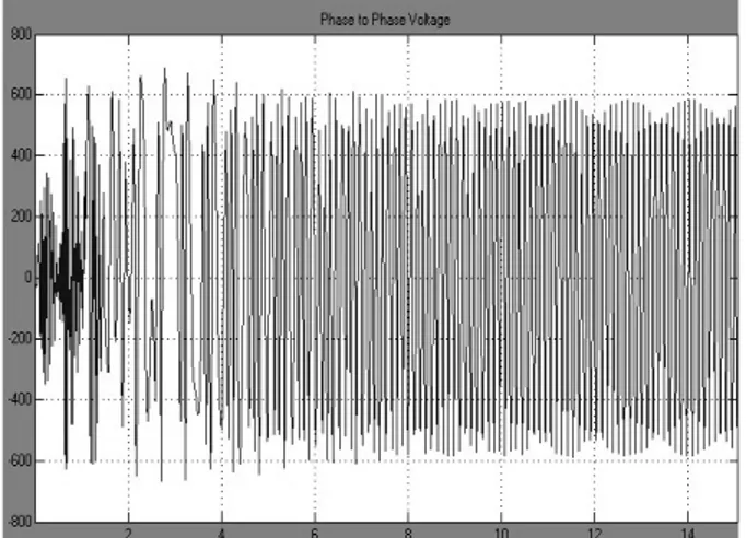
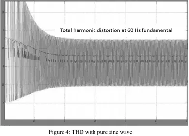
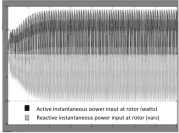
Simulation and Analysis of Induced Harmonics and Reactive Power of a Rotor-Fed Induction Generator with PWM Inverter
Texto
Imagem
Documentos relacionados
This paper aims at developing the control circuit for a single phase inverter which produces a pure sine wave with an output voltage that has the same magnitude and
This venture "Simulation and Implementation of Γ -Z-Source Inverters" is made out of Voltage- sort Γ -Z source inverters are proposed in this letter.. They utilize
The boost DC-AC inverter was applied to PVarray and simulated.The output of inverter is 150 V – AC obtained in single stage of power conversion( i.e.,boosting the
The structure of the remelting zone of the steel C90 steel be- fore conventional tempering consitute cells, dendritic cells, sur- rounded with the cementite, inside of
Simulation circuit of WECS with PMSG using Fuzzy Logic controller is shown in the Figure 12 .The output voltage for Buck Boost Converter and SPWM based inverter is
Abstract: This paper presents PIC microcontroller based PWM inverter controlled four switch three phase inverter (FSTPI) fed Induction Motor drive.. The advantage of this
The proposed PRDCL circuit is aimed at both providing short zero voltage intervals in the dc link of the PWM inverter during the required inverter device switching
The main feature of the modulation scheme lies in its ability to eliminate the harmonics in the inverter output voltages.The harmonic content and THD of the
