Carolina Guimarães CASTRO(a) Karla ZANCOPÉ(a)
Crisnicaw VERÍSSIMO(b) Carlos José SOARES(b)
Flávio Domingues das NEVES(a)
(a)Universidade Federal de Uberlândia – UFU, School of Dentistry, Department of Occlusion, Fixed Prostheses, and Dental Materials, Uberlândia, MG, Brazil.
(b)Universidade Federal de Uberlândia – UFU, School of Dentistry, Department of Operative Dentistry and Dental Materials, Uberlândia, MG, Brazil.
Strain analysis of different diameter
Morse taper implants under
overloading compressive conditions
Abstract: The aim of this study was to evaluate the amount of deformation from compression caused by different diameters of Morse taper implants and the residual deformation after load removal. Thirty Morse taper implants lacking external threads were divided into 3 groups (n = 10) according to their diameter as follows: 3.5 mm, 4.0 mm and 5.0 mm. Two-piece abutments were ixed into the implants, and the samples were subjected to compressive axial loading up to 1500 N of force. During the test, one strain gauge remained ixed to the cervical portion of each implant to measure the strain variation. The strain values were recorded at two different time points: at the maximum load (1500 N) and 60 seconds after load removal. To calculate the strain at the implant/abutment interface, a mathematical formula was applied. Data were analyzed using a one-way Anova and Tukey’s test (α = 0.05). The 5.0 mm diameter implant showed a signiicantly lower strain (650.5 μS ± 170.0) than the 4.0 mm group (1170.2 μS ± 374.7) and the 3.5 mm group (1388.1 μS ± 326.6) (p < 0.001), regardless of the load presence. The strain values decreased by approximately 50% after removal of the load, regardless of the implant diameter. The 5.0 mm implant showed a signiicantly lower strain at the implant/abutment interface (943.4 μS ± 504.5) than the 4.0 mm group (1057.4 μS ± 681.3) and the 3.5 mm group (1159.6 μS ± 425.9) (p < 0.001). According to the results of this study, the diameter inluenced the strain around the internal and external walls of the cervical region of Morse taper implants; all diameters demonstrated clinically acceptable values of strain.
Keywords: Dental Implants; Dental Implant-Abutment Design; Mechanical Phenomena.
Introduction
Excessive occlusal loading or creep deformation of the screw-implant interface could lead to clinical complications such as screw loosening.1 For a Morse taper implant, the friction at the tapered connection results in a high contact pressure and frictional resistance, causing limited strain that must be absorbed by the abutment screw thread, which differs from the butt joint where the screw alone keeps the abutment connected to the implant.2,3 This mechanism provides excellent biological and mechanical stability and unusual prosthetic versatility;4 in fact, the prosthetic versatility is similar to that of a hexagonal implant. A total of 2,549 Morse taper connection implants that were placed in 893 patients were evaluated, and the incidence of abutment loosening was 0.37% for Declaration of Interests: The authors
certify that they have no commercial or associative interest that represents a conflict of interest in connection with the manuscript.
Corresponding Author: Flávio Domingues das Neves E-mail: [email protected]
DOI: 10.1590/1807-3107BOR-2015.vol29.0028
Submitted: Feb 07, 2014
single tooth replacements alone. No complications were observed at the implant-abutment interface for ixed partial prostheses and ixed full-arch prostheses, and no abutment fractures were observed.5 Contact and friction play crucial roles in the mechanical behavior of the individual parts of a system, including oral implants.3,6
The tapered interference it relies on a large contact pressure and the resulting frictional resistance in the mating region of the implant–abutment interface to provide a secure connection.7 In general, interference it implants have a hub and shaft that connect to each other and do not require a third member, such as a key, pin, bolt, or screw. The connection allows for load transmission due to the frictional forces between the mating surfaces where the shaft has a slightly larger diameter than the hub. The dependent characteristics of the interference it, including the pullout/insertion forces and the stress distribution in the members, depend on the taper angle, contact length, inner and outer diameters of the members, depth of insertion, material properties and coeficient of friction.7
Clinically, straight and wide diameter implants are used in many clinical scenarios, including the use of single dental implants. In Morse taper implants, the measurements of the internal cone are the same, regardless of the implant diameter. In straight diameter implants, the thickness of the titanium wall around the implants is thinner than in wide diameter implants. These implants, submitted to overload, especially in single implants in patients who have an oral dysfunction, could cause a design modiication of the Morse taper implant.
Even though Morse taper implants with different outer diameters have the same internal conical diameter, there is a difference in the thickness of the cervical portions of different implants. In this context, there is a lack of research evaluating the effect of axial compressive loading on dimensional changes in the cervical portion of Morse taper implants with different diameters. The strain around these walls can be measured using strain gauge analysis, which is a non-destructive method.
Therefore, the aim of this study was to evaluate the deformation caused by compression in different
diameters of Morse taper implants and the residual deformation after removal of the load. The hypothesis in this study was that the diameter of Morse taper implants affects the strain variation of the cervical portion.
Methodology
Samples
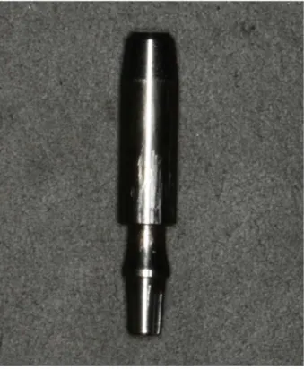
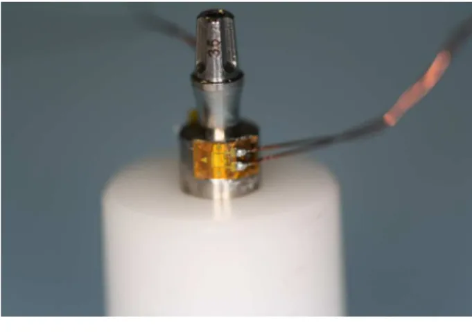
Thirty Morse taper implants (Neodent, Curitiba, Brazil) were divided into the following 3 groups (n = 10) according to implant diameter: 3.5 mm, 4.0 mm and 5.0 mm. The implants (Figure 1) were produced speciically for this study and lacked external threads to allow for strain gauge ixation (Figure 2). Each implant was ixed to a two-piece abutment (Universal Post Exact, Neodent, Curitiba, Brazil). The material characteristics are described in Table 1.
Strain Gauge Test
A strain gauge (PA-06-040AB-120 LEN, Excel Sensores, São Paulo, Brazil) was attached to each specimen with cyanoacrylate glue (Super Bonder Loctite, Rocky Hill, USA). The gauge was a custom
apparatus that enabled specimen stabilization and was placed perpendicular to the long axis of the implant. The strain gauge wires were connected to the data acquisition device (ADS0500IP Lynx, São Paulo, Brazil).
The abutments were placed using 15 N-cm of insertion torque, as recommended by the manufacturer. The samples were subjected to axial compressive loading (Figure 3) with a crosshead speed of 0.5 mm/min in a universal testing machine (EMIC, 2000DL, São José dos Pinhais, Brazil) until 1500 N of loading force was reached. The 1500 N loading force was based on pilot studies that deined the load value required to cause physical deformation of the 5.0 mm diameter Morse taper implant under axial compressive loading. A study reported an occlusal force in an axial direction on implants of up to 847 N for men and 595 N for women with normal occlusion.8 Compared to the occlusal loading measured in patients with a normal dentition, the absence of a periodontal ligament may lead to occlusal overloading and implant failure due to the inability to distribute occlusal forces, axial transmission of these forces, and the absence of periodontal proprioceptors.
Therefore, we simulated overloaded forces to test the mechanical characteristic of this implant under this
condition. A study9 reported that the mean voluntary maximal bite force for male bruxers was 1009 ± 290 N. During all tests, the strain gauge remained ixed on the cervical portion of the implant to measure the strain variation. The load was removed and the strain measurement was recorded for 60 seconds.
Data were evaluated statistically with a one-way ANOVA (α = 0.05) and Tukey’s test. The strain in a thick cylinder with internal pressure was higher in the interior of the canal and decreased as it approached the external surface. To measure the internal strain, the following formula10 was applied: εA/B = (b² + a²) / 2a², where εA/B = the relationship between the internal strain and external strain, a = internal canal radius, and b = external canal radius.
Results
The implant diameter signiicantly inluenced the strain around the cervical region of the Morse taper implants. The implant with a 5.0 mm diameter had signiicantly lower strain than the other groups (p < 0.001), regardless of the presence of a load (Table 2).
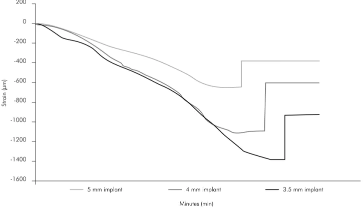
The strain values had a 50% reduction after load removal, regardless of the implant diameter. Figure 4 illustrates the strain pattern for all implant diameters according to the loading variation (0 - 1500 - 0 N).
The internal strain values, calculated according to the formula εA/B = (b² + a²) / 2a² are summarized
in Table 3. The implant diameter significantly inluenced the internal strain around the cervical region of the Morse taper implants. The 5.0 mm Table 1. Description of materials.
Material Description Quantity (un)
Cylindrical Morse taper Implant 3.5 x 13 mm 10 Cylindrical Morse taper Implant 4.0 x 13 mm 10 Cylindrical Morse taper Implant 5.0 x 13 mm 10 Universal CM Post (two pieces) 3.3 x 4 x 3.5 mm 30
diameter implants showed a signiicantly lower strain than the other groups (p < 0.001).
Discussion
The hypothesis was accepted. The diameter inluenced the strain around the internal and external
wall of the cervical region of Morse taper implants. The two-piece abutment allowed us to slide the abutment into the internal conical surface of the implant during axial loading.
When the implant diameters were analyzed, there was a 20% reduction in the strain between Table 3. The mean internal strain values (µS) ± SDs and statistical categories defined via Tukey’s test (n = 10) according to the
formula εA/B = (b² + a²) / 2a².
Strain criteria Ø implant
5.0 mm 4.0 mm 3.5 mm
Strain at maximum load (1500 N) 1625.7 ± 590.2A 2082 ± 758.5B 2052.2 ± 681.3B
Residual Strain (after removing the load) 943.4 ± 504.5A 1057.4 ± 681.3B 1159.6 ± 425.9C
Means followed by the different letters indicate statistically significant differences at 5% compared to similar values from different diameter implants. Table 2. The mean strain values (µS) ± SDs and statistical categories defined via Tukey’s test (n = 10) for the three different implant diameters.
Strain criteria Ø implant
5.0 mm 4.0 mm 3.5 mm
Strain at maximum load (1500 N) 650.5 ± 170.0A 1170.2 ± 374.7B 1388.1 ± 326.6B
Residual Strain (after removing the load) 377.5 ± 106.9A 594.3 ± 173.6B 784.4 ± 128.8C
Means followed by the different letters indicate statistically significant differences at 5% compared to the similar values from different diameter implants.
Figure 4. Strain (µS) curve obtained for the three different implant diameters according to the loading 0 - 1500 - 0 N.
200
Strain (µm)
0
-200
-400
-600
-800
-1000
-1200
-1400
-1600
5 mm implant 4 mm implant 3.5 mm implant
the 5.0 and 4.0 mm implants and a 12.5% reduction in the strain between the 4.0 and 3.5 mm implants. These percentage differences most likely caused the significant difference between the 5.0 and 4.0 mm groups, as well as the statistical similarity between the 4.0 mm and 3.5 mm groups. When the residual internal strains were analyzed, there were significant differences between all groups, which could be due to the thickness variations between the cervical portions of single implants and the presence of the abutment, which worked as a wedge by forcing the entrance of a single implant. Clinically, masticatory forces could result in a residual stress over implants, resulting in plastic deformation. The response of bone tissue around these implants must be investigated. However, this extreme situation occurs in only male bruxers over years of dysfunction. Further studies with cyclic loading to simulate this dysfunction are still needed.
As illustrated in Figure 4, there were differences in the observed values with the same strain variation behavior between the three implant diameters. This could be explained by the differences between the radii of all groups. In this study, the internal radius for all implant diameters was 1.25 mm, and the external radius varied between 1.75, 2.00 and 2.50 mm for the 3.5, 4.0 and 5.0 mm diameter implants, respectively. Under the same loading condition, the 3.5 mm implant experienced approximately twice the strain variation compared to the 5.0 mm implant. All of the diameters had a residual strain of approximately 50% of the maximum strain observed at a 1500 N loading force.
Table 2 summarizes the residual strain values resulting from abutment placement. Because residual strain did not dissipate with time, it increased the risk of the plastic deformation. The same proportion of twice the strain variation between the 3.5 and 5.0 mm groups was observed for the residual strain values. Based on these results, when placing single implants in male bruxers, a 5 mm diameter implant would be clinically better
than a 3.5 mm or 4 mm diameter implant in the posterior regions of mouth for the following two reasons: the molar regions primarily receive axial loads11 and posterior regions are subjected to the highest forces in the arch.12 However, the authors of the present study emphasize that different implant diameters demonstrate clinically acceptable values of strain during normal function according to Figure 4.
T h e s t r a i n g aug e a n a l y s i s w a s c h o s e n because it is a non-destructive methodolog y that provides a better understanding of the biomechanical behavior of dental implants.13,14 An advantage of the present strain gauge study is the large number of samples per group (n = 10), i ncreasi ng the reliabilit y of the data. Fi n ite element analysis (FEA) could complement the present findings. In another study,7 the FEA and closed-form results were in agreement regarding the contact pressure in the tapered interference connection of dental implants, showing that the contact pressure increased at the locations where the implant was thicker, which provided more resistance to deformation. Further studies are still needed to understand the influence of preloading on Morse taper abutments and how much stress would be transmitted to the surrounding bone from different implant diameters.
Conclusion
According to the results in this study, the diameter inluenced the strain around the internal and external walls of the cervical region of Morse taper implants. All diameters demonstrated clinically acceptable values of strain.
Acknowledgements
1. Schwarz MS. Mechanical complications of dental implants.
Clin Oral Implants Res. 2000;11(Suppl 1):156-8.
2. Haack JE, Sakaguchi RL, Sun T, Coffey JP. Elongation and preload stress in dental implant abutment screws. Int J Oral Maxillofac Implants. 1995 Sep-Oct;10(5):529-36.
3. Merz BR, Hunenbart S, Belser UC. Mechanics of the im -plant-abutment connection: an 8-degree taper compared to
a butt joint connection. Int J Oral Maxillofac Implants. 2000 Jul-Aug;15(4):519-26.
4. Nentwig GH. Ankylos implant system: concept and clinical
application. J Oral Implantol. 2004;30(3):171-7.
5. Mangano C, Mangano F, Shibli JA, Tettamanti L, Figliuzzi
M, D’Avila S, et al. Prospective evaluation of 2,549 Morse taper connection implants: 1- to 6-year data. J Periodontol. 2011 Jan;82(1):52-61.
6. Sakaguchi RL, Borgersen SE. Nonlinear contact analysis of
preload in dental implant screws. Int J Oral Maxillofac Im
-plants. 1995 May-Jun;10(3):295-302.
7. Bozkaya D, Müftü S. Mechanics of the tapered interference fit in dental implants. J Biomech. 2003 Nov;36(11):1649-58.
8. Waltimo A, Könönen M. Maximal bite force and its associa-tion with signs and symptoms of craniomandibular
disor-ders in young Finnish non-patients. Acta Odontol Scand. 1995 Aug;53(4):254-8.
9. Cosme DC, Baldisserotto SM, Canabarro SA, Shinkai RS. Bruxism and voluntary maximal bite force in young dentate
adults. Int J Prosthodont. 2005 Jul-Aug;18(4):328-32.
10. Popov EP. Mechanics of materials. 2nd ed. Englewood Cliffs:
Prentice-Hall Inc.; 1976. 590 p.
11. Castro CG, Santana FR, Roscoe MG, Simamoto Jr PC, San
-tos-Filho PC, Soares CJ. Fracture resistance and mode of failure of various types of root filled teeth. Int Endod J. 2012 Sep;45(9):840-7.
12. Fernandes AS, Dessai GS. Factors affecting the fracture resistance of post-core reconstructed teeth: a review. Int J Prosthodont. 2001 Jul-Aug;14(4):355-63.
13. Vasconcellos DK, Özcan M, Maziero Volpato CÂ, Bottino
MA, Yener ES. Strain gauge analysis of the effect of porce -lain firing simulation on the prosthetic misfit of
implant-supported frameworks. Implant Dent. 2012 Jun;21(3):225-9.
14. Harel N, Eshkol-Yogev I, Piek D, Livne S, Lavi D, Orm
-ianer Z. Bone microstrain values of 1-piece and 2-piece implants subjected to mechanical loading. Implant Dent. 2013 Jun;22(3):277-81.