ISSN 0104-6632 Printed in Brazil
of Chemical
Engineering
Vol. 21, No. 03, pp. 415 - 422, July - September 2004
CHEMICAL ABSORPTION OF H
2
S FOR
BIOGAS PURIFICATION
M.S. Horikawa
1, F. Rossi
1, M.L. Gimenes
1*, C.M.M. Costa
2and M.G.C. da Silva
31
Universidade Estadual de Maringá, Departamento de Engenharia Química, Phone +(55) (44) 261-4323, Fax +(55) (44) 263-3440, Bloco D90,
Av. Colombo 5790, CEP 87.020-900, Maringá - PR, Brazil. E-mail: [email protected]
2
Universidade Estadual de Maringá, Departamento de Química, CEP 87.020-900, Maringá - PR, Brazil.
3
Universidade Estadual de Campinas, Faculdade de Engenharia Química, Campinas - SP, Brasil
(Received: December 5, 2002 ; Accepted: February, 12, 2004)
Abstract - This work presents an experimental study of purification of a biogas by removal of its hydrogen sulphide (H2S) content. The H2S was removed by means of chemical absorption in an iron-chelated solution catalyzed by Fe/EDTA, which converts H2S into elemental sulphur (S). Preparation of the catalyst solution and the results of biogas component absorption in the catalyst solution (0.2 mol/L) are presented. These results are compared with those for physical absorption into pure water under similar conditions. Experimental results demonstrate that, under the same experimental conditions, a higher percentage of H2S can be removed in the catalytic solution than in water. In a continuous counter current using adequate flow-rate phases contact at room temperature and low gas pressure, the results demonstflow-rate that is possible to totally remove the H2S from the biogas with the prepared catalytic solution.
Keywords: biogas purification, H2S removal, Fe/EDTA catalyst.
INTRODUCTION On the other hand, biogas is an attractive source of energy due to its high methane content. However, direct utilisation of biogas as fuel without removal of H2S leads to the formation of sulphur dioxide (SO2),
which is another toxic pollutant and a major contributor to acid rain in the atmosphere.
The anaerobic process has frequently been used to treat wastewaters and solid residues. As it causes the degradation of organic compounds in the absence of molecular oxygen, this biological process produces the co-product biogas, a mixture composed mainly of methane, carbon dioxide and hydrogen sulphide (H2S) (Corbitt, 1990).
There are several process presented in literature (Bland and Davidson, 1967; Kohl and Riesenfeld, 1985; Horikawa, 2001) that deal with means of removing H2S. Many of them only remove this
pollutant from the gaseous stream, but do not convert the H2S into a more stable or valuable product, as do
processes that transform H2S into S. The advantage
of these processes is the conversion of a pollutant into a chemical product or at least a solid residue that can be disposed of easily and safely.
Biogas emissions can cause damage to the environment due to the presence of the pollutant hydrogen sulphide, which is harmful to human beings and animals. At lower concentrations, this gas has an unpleasant odour; at higher concentrations, it can be life-threatening. The recommended industrial exposure limits are from 8 to 10 ppm for 8 hours a
iron-chelated solutions does fit in this approach and offers extra advantages, such as the high efficiency of H2S removal, the selective removal of H2S and the
low consumption of the chemicals because iron-chelated solutions functions as a pseudo-catalyst that can be regenerated.
In processes based on iron chelating, H2S is
initially physically absorbed into water undergoing the dissociation according to reactions 1, 2 and 3 (O’Brien, 1991).
H2S (g) + H2O H2S (aq) (1)
H2S (aq) H+ + HS (2)
HS H+ + S2 (3)
The formation of S occurs by means of sulphide oxidation by the chelated iron according to the reaction described by Equation (4).
S2 + 2Fe+3 S0 + 2Fe+2 (4)
Regeneration of the aqueous iron-chelated solution occurs by means of its oxygenation, according to Equation (5), followed by conversion of the pseudo-catalyst into its active form Fe+3 [Equation (6)].
½ O2(g) + H2O (l) o ½ O2 (aq) (5)
½ O2(aq) + 2Fe+2o 2Fe+3 +2OH (6)
The overall reaction is expressed in Equation (7) (O’Brien, 1991).
H2S + ½ O2(g)o S0 + H2O (7)
Several chelate agents that can be used for the specific proposal of reaction (7) have been studied in the literature (Wubs and Beenackers, 1993), with the EDTA (ethylenediaminetetraacetate) being the most common chelate used.
In the iron chelated based process, the sulphur produced is easily recoverable from the slurry by sedimentation or filtration operations and the whole process can be carried out at ambient temperature. These advantages are quite important for biogas purification because of the low content of H2S in the
biogas and the ambient temperature in the bioreactor. Although EDTA is the most common agent reported in the literature, there is very little information about preparation of the Fe-EDTA
catalyst complex. In addition, no process data is available in the published literature that allows designing a process for biogas purification (Horikawa, 2001).
In addition to obtaining the Fe-EDTA catalyst complex, this work aims at studying the potential offered by the more environmentally appropriate process for transforming gas sulphide from biogas into S.
MATERIALS AND METHODS
Preparation of Fe-EDTA Catalyst Solution
FeCl2 was reported in the literature (Wubs and
Beenackers., 1994) as the salt used to prepare the iron chelate Fe-EDTA. Preparation of this salt is difficult due to its extreme instability. In this work, FeBr2 salt was used instead for synthesis of the
homogeneous Fe-EDTA catalyst. The FeBr2salt was
prepared at a controlled temperature in argon in a closed system. In this system iron powder was added to HBr (98%) solution under controlled stirring for 5 to 6 hours until iron powder had been completely transformed into FeBr2. After filtering, the solution
was dried in vacuum to obtain the salt.
The Fe-EDTA catalyst solution was synthesised from a 0.2 M solution of EDTA, which had been previously prepared and standardized with a 0.1 M zinc solution and had its pH adjusted to a value of 9.5. In argon, the prepared FeBr2salt was added into
the EDTA solution to form the final Fe-EDTA catalyst solution. The ratio of iron to chelate agent used in the preparation of the catalyst was 1.06 (Horikawa, 2001).
Experimental Rig for H2S Removal
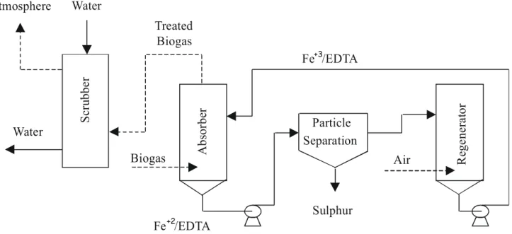
Figure 1 shows a sketch of the experimental rig used to test removal of the H2S from the biogas
stream.
The complete system comprises an absorber column (ID 5.4 cm, height 36 cm), a particle separator (filter) and a regenerating column (ID 5.4 cm, height 36 cm). Under continuous operational conditions, the biogas is introduced at the bottom of the absorber column as small bubbles, passing through the Fe/EDTA solution flowing downwards to the particle separator. In this column the H2S is
solution is regenerated into Fe+3/EDTA in a bubbling air column.
A synthetic biogas was used in all experiments. The composition of this biogas was very similar to that of a biogas from a UASB (Up-flow Anaerobic Sludge Biodigestor) used to treat gelatine industry wastewater (Horikawa, 2001). Compositions of both biogases are presented in Table 1.
Samples of the inlet and outlet (or treated) biogas were taken during experimental tests. The compositions of these samples were determined by gas chromatography using a Porapak Q column in a 2000 Thermo Quest Varian model chromatograph. H2S
removal, expressed as a percentage, was calculated by dividing the difference between the inlet and the outlet volume compositions by the inlet composition.
For safety and environmental reasons, in all experiments the treated biogas leaving the absorption column was washed with water in a packed column to remove residual traces of H2S.
Atmosphere
Particle Separation Water
Biogas Treated Water
Fe+2/EDTA
Fe+3/EDTA
Biogas Air
Sulphur
Abs
or
b
er
R
ege
ne
ra
to
r
Sc
ru
b
b
er
Figure 1: Experimental rig for biogas purification
Table 1: Biogas compositons in % of volume
Gases UASB* Biodigestor Synthetic Mixture
CH4 81.1 79.68
CO2 14.0 14.13
H2S 2.2 2.36
N2+ O2 2.7 3.66
*(Horikawa, 2001).
RESULTS AND DISCUSSION
The first test was carried out in the experimental rig under batch operation conditions, using only the absorption column. The aim of this test was to verify the efficacy of the prepared catalyst solution for removing H2S and the behaviour of gases other than
H2S and also to determine the catalyst deactivation
time. Results of this test, conducted using a volume of 500 ml of catalyst solution, are presented in Figures 2 and 3.
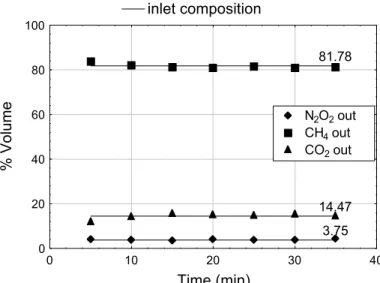
In Figure 2 the volumetric compositions are presented on an H2S-free basis. The straight lines
represent the measured inlet composition of the biogas (81.78% CH4; 14.47% CO2; 3.75% NO2 +
the absorber outlet biogas, measured according to elapsed time. Results in this figure demonstrate that volumetric compositions (without H2S) of gases
other than H2S are maintained constant, except for
the component CO2, which is slightly absorbed at the
beginning of bubbling, thus increasing the outlet composition of the CH4. After the saturation of the
catalyst solution with the absorbed CO2 the outlet
composition is restored to the inlet value.
The batch test demonstrated that the volume of solution used, containing 0.2 mol/L of Fe-EDTA catalyst, is effective in initially removing all H2S
present in the biogas. The catalytic solution begins to loose removal efficiency after 4 min and its complete deactivation occurs after 35 min., as illustrated in Figure 3.
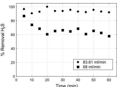
Choosing the deactivation time as the space-time (Levenspiel, 1994), flow-rates of the catalytic solution were estimated in order to obtain the required percentage of H2S removal for a known
biogas flow-rate, in continuous counter-current contact. The estimated flow-rates of 83 and 68 ml/min of catalytic solution were used in continuous mode operation experiments, for which results are presented in Figure 4. It can be seen in this figure that, for a biogas flow-rate of 1000 ml/min and 2.2 kgf/cm2 pressure, approximately 90% and 70% of the H2S can be removed with the catalytic solution
flowing at 83 and 68 ml/min, respectively. This means that above a flow-rate of 83 ml/min or with an appropriate ratio of gas contacting phases, it is possible to achieve total removal of H2S.
inlet composition
81.78
14.47
3.75
0 10 20 30 40
Time (min)
0 20 40 60 80 100
% Volume
N2O2 out
CH4 out
CO2 out
Figure 2: Inlet and outlet biogas composition of the absorption column (free base of H2S, G = 1000 ml/min, P=2.2 kgf/cm2– Batch experiment)
0 10 20 30 40
Time (min)
0 20 40 60 80 100
% Removal H
2
S
Figure 3: H2S removal using Fe-EDTA solution (G= 1000 ml/min,
0 10 20 30 40 50 60
Time (min)
0 20 40 60 80 100
% Removal H
2
S
83.61 ml/min 68 ml/min
Figure 4: H2S removal using Fe-EDTA solution
(G = 1000 ml/min, P = 2.2 kgf/cm2)
Figure 5 shows the effect of inlet biogas pressure on the removal of H2S through counter-current
continuous absorption. As expected for a lower inlet pressure, which corresponds to a lower H2S
concentration, a higher percentage of H2S removal is
achieved more easily.
Similarly to the batch test, for continuous counter current contacting the outlet volumetric composition (H2S free base) of all gases was compared to the
respective inlet value. The results of this comparison allowed the observation that CO2 was continuously
absorbed into the catalytic solution, while no absorption was observed for other gases than H2S.
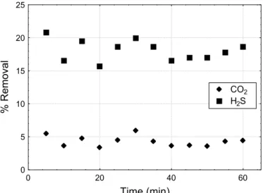
Physical absorption of biogas components was carried out in the experimental rig using distilled water under the same experimental conditions as
those for absorption into Fe-EDTA catalyst solution. These results, as presented in Figure 6, show a higher removal of H2S than of CO2. No physical
absorption into water was verified for other biogas components.
Figures 7 and 8 contain comparisons of the absorption into distilled water and into the Fe-EDTA catalytic solution for H2S and CO2, respectively. In
Figure 7 the increase in the rate of absorption of H2S
caused by the chemical reaction is evident, thus demonstrating the effectiveness of the prepared catalyst. In Figure 8, no chemical reaction seems to take place in the absorption of CO2 into the
Fe-EDTA solution; even so, increased removal is observed, which may be due to an increase in CO2
solubility in the Fe-EDTA solution.
0 10 20 30 40 50 60
Time (min)
0 20 40 60 80 100
% Removal H
2
S
P=2.2 kgf/cm2 P=1.2 kgf/cm2
Figure 5: H2S removal using Fe-EDTA solution
0 20 40 60
Time (min)
0 5 10 15 20 25
% Removal
CO2 H2S
Figure 6: Absorption of CO2 and H2S into pure water
(G = 1000 ml/min, P=2.2 kgf/cm2, L= 88 ml/min)
0 20 40 60
Time (min)
0 20 40 60 80 100
% Removal H
2
S
Water Solution
Figure 7: Removal of H2S in distilled water and in Fe-EDTA solution
(G = 1000 ml/min, P=2.2 kgf/cm2, Lwater= 88 ml/min, Lsolution = 83 ml/min)
0 20 40 60
Time (min)
0 20 40 60 80 100
% Removal CO
2
Water Solution
Figure 8: Absorption of CO2 into pure water and in Fe-EDTA solution
Froning et al. (in Kohl and Riesenfeld, 1985) obtained the following equations to estimate the distribution coefficient K from experimental data on liquid-vapor equilibrium for the H2S – CO2– CH4–
water system:
4
2
2
CH AG
CO AG
H S AG
306000 2.19 T
K 3910 14.5 X 121.6
P T P
3500 T
K 0.12 T 360 8.3 X 5825
P P
1087 T
K 4.53 110 4.65 X
T P
P I
I
(8)
In Equation (8) P is system pressure (psia), T the temperature (oF), XAG the molar fraction of CO2plus
H2S in the gas phase, and I the ratio between the
molar fraction of H2S in the gas phase and the value
of XAG.
In Table 2 the values of K for CO2, H2S and CH4,
estimated by means of the set of Equations (8) for conditions used in the absorption of the biogas into pure water, are presented. In making these estimates the small amounts of N2 and O2 gases were
incorporated into that of CH4.
According to Coulson and Richardson (1991), by
using Equation (9) it is possible to estimate the composition of gases leaving the absorber from K values, if it is assumed that equilibrium has been reached.
m 1 m 1
G .(Y Y) L .(X X) (9)
where Gm and Lm are the molar flow-rates for the gas
and liquid phases and the pairs (X1, Y1) and (X, Y)
are the liquid and gas compositions at the bottom and top of the absorber column, respectively.
From experimental values of Gm= 9.51.10-2
mol/min and Lm= 4.89 mol/min the values of the exit
compositions (Yout-equil) were estimated by assuming
equilibrium was reached in the absorption of biogas into water. In Table 3 these values together with those obtained experimentally are presented.
Data in Table 3 show that values of Yout obtained
under the assumption of equilibrium are smaller than the experimental values. This demonstrates that equilibrium was not reached in the experiments. However, it can be observed that, as the difference between the values is quite small, the experimental conditions used for contacting liquid and gas phases by means of bubbling have provided quite a good mass transfer.
Table 2: Values of the distribution coefficient K in pure water
Compound (y) K (y/x)
CH4 0.8351 19380.8
CO2 0.1413 757.9
H2S 0.0236 261.8
Table 3: Physical absorption of biogas compound into pure water
Compound Yout-equil. Yout-exp
CH4 0.8478 0.8457
CO2 0.1317 0.1351
H2S 0.0189 0.0192
CONCLUSIONS
Results obtained in this work demonstrate that it is possible to achieve the complete removal of H2S
from biogas using an iron-chelated process that operates at ambient temperature. In this process the total removal of H2S depends on the use of the
adequate ratio of gas to liquid flow-rates.
Results presented show that the almost selective increased rate of H2S removal is not the only
advantage of this process of chemical absorption. The main advantage is the transformation of H2S into
S thereby eliminating the pollution potential of H2S.
The catalytic solution Fe-EDTA used in the experiment was prepared using FeBr2, a salt different
solution prepared based on this salt was quite effective in removal of the H2S gas. Results
demonstrate that this catalytic solution is able to absorb more CO2 than pure water.
NOMENCLATURE
XAG Molar fraction of CO2 plus H2S in the gas
phase
Gm Molar flow-rate for the gas phase (mol/min)
K Distribution coefficient (Y/X)
Lm Molar flow-rate for the liquid phase (mol/min)
P System pressure (psia)
I Ratio of molar fraction of H2S to molar
fraction of CO2plus H2S in the gas phase
T Temperature ( oF);
X Composition in the liquid phase Y Composition in the gas phase
REFERENCES
Bland, W.F. and Davidson, R.L., Petroleum Processing Handbook, 1st edition, New York, McGraw Hill, Inc. (1967).
Corbitt, R.A., Standard Handbook of Environmental Engineering, 1st edition, New York, McGraw Hill, Inc. (1990).
Coulson, J.M. and Richardson, J.F., Chemical Engineering – Particle Technology and Separation Process, vol. 2, 4th edition, Pergamon Press, Oxford (1991).
Horikawa, M.S., Purificação de Biogás - Remoção de H2S – MSc. dissertation, PEQ, Universidade
Estadual de Maringá, Brazil (2001).
Kohl, A.L. and Riesenfeld, F.C., Gas Purification, 4th edition Gulf Publishing Company, Houston, Texas, (1985).
Levenspiel, O., Engenharia das Reações Químicas -Cinética Química Aplicada, – vol. 1, São Paulo, S.P. Brazil, – Editora Edgard Blucher (1994). O’Brien, M., Catalytic Oxidation of Sulfides in
Biogas, Ventilation Air and Wastewater Streams from Anaerobic Digesters, Proceedings 1991 Food Industry Environmental Conference, USA (1991). Wubs, H.J. and Beenackers, A.A.C.M., Kinetics of
the Oxidation of Ferrous Chelates of EDTA and HEDTA into Aqueous Solutions, Ind. Eng. Chem. Res., vol. 32, pp. 2580 - 2594 (1993). Wubs, H.J. and Beenackers, A.A.C.M., Kinetics of
H2S Absorption into Aqueous Ferric Solutions of