ISSN 0104-6632 Printed in Brazil
www.abeq.org.br/bjche
Vol. 26, No. 02, pp. 331 - 341, April - June, 2009
Brazilian Journal
of Chemical
Engineering
MODELING AND EXPERIMENTAL STUDY
OF HYDRODYNAMIC AND DRYING
CHARACTERISTICS OF AN INDUSTRIAL
ROTARY DRYER
N. J. Fernandes, C. H. Ataíde and M. A. S. Barrozo
*Universidade Federal de Uberlândia, Faculdade de Engenharia Química,
Av. João Naves de Ávila 2121, Bloco K, Campus Santa Mônica, CEP: 38408-100, Uberlândia - MG, Brazil. E-mail: [email protected]
(Submitted: July 9, 2008 ; Revised: September 2, 2008 ; Accepted: September 26, 2008)
Abstract - The purpose of this work was to analyze the hydrodynamic and drying aspects of a rotary dryer used in a fertilizer industry. A set of equations to predict the solids holdup in the flights, the length of fall, the residence time of particles and the drying variables was evaluated by comparison to experimental measurements performed in an industrial rotary dryer of the Copebras Fertilizer Company, located in Catalão, state of Goias, Center-west of Brazil. Because of precise estimations, these equations may be used to design and predict the solids cascading behavior in industrial rotary dryers. Despite larger deviations, reaching 20%, the drying model can also be used for design calculations and process simulations.
Keywords: Industrial rotary dryer; Hydrodynamic; Drying.
INTRODUCTION
The worldwide population increased from 3 billion people in 1960 to 6 billion people in 2000. In order to take into consideration the demand for food, the optimization of agricultural productivity is quite important. Fertilizers are products compounded with nutrients that increase the growth and the productivity of plants, improving the natural soil fertility or giving back the elements taken away from the soil due to erosion or to previous cultures.
In the production of granulated fertilizers, the raw material (water, ammonia, sulphuric acid and steam among others) are dosed in the equipment called granulator and its goal is to adequate the product to the chemical specifications and increase the size of the particles until they reach the desired standard (between 2 and 4 mm). After this process, there is
the drying operation, which is responsible for removing the volatile substances used in the granulation.
Drying, being one of the most energy-intensive operations, is of great importance in the fertilizer industry. Despite its importance, in many cases the design and operation of dryers is done according to empiricism, based on the “experience” of engineers.
Rotary drums are often used for drying in the fertilizer industry. The dryer consists basically of a cylindrical shell inclined at a small angle to the horizontal. Wet feed is introduced into the upper end of the dryer and the dried product withdrawn at the lower end. The inside of the shell is equipped with lifting flights.
air stream. The majority of the drying occurs during this period, when the solids are in intimate contact with the air. Therefore, a good flight design is essential to promote the gas–solid contact that is required for rapid and homogeneous drying (Baker, 1988).
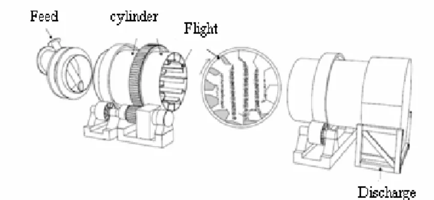
The movement of particles in rotating drums depends on of flights and shell design as well as on the operating conditions. Thus, rotary dryers represent one of the greatest challenges in theoretical modeling of dryers (Sherrit et al., 1993). The complex combination of particles being lifted by the flights, sliding and rolling, then falling in spreading cascades through an air stream and re-entering the bed at the bottom, possibly with bouncing and rolling, is very difficult to analyze (Kemp, 2004). Figure 1 shows a rotary dryer and Figure 2 shows a scheme of the movement of solids inside this dryer.
Knowledge of the quantity of solids held up in the flights is essential to ensure that the drum loading is
close to optimum. If the flights are underfilled, the dryer will be operating below capacity and therefore inefficiently. On the other hand, excessive overloading of the drum will result in a proportion of the material being transported by kiln action. This will reduce the average solids residence time and may be detrimental to product quality (Baker, 1988).
The modeling of drying is another challenge in this process. This modeling needs mass and energy balance equations applied to both fluid and solid phases and requires constitutive equations for the heat transfer coefficient, the drying kinetics and the equilibrium moisture content of the solid material.
The purpose of this work was to analyze some existing models to forecast the hydrodynamic and drying variables of an industrial rotary dryer for granulated fertilizers (GTSP). The industrial dryer of the present work is set up in Copebras Fertilizer Company located in Catalão, state of Goias, Center-west of Brazil.
Figure 1: Scheme of a typical flighted rotary dryer
HYDRODYNAMIC AND DRYING EQUATIONS
Solids Holdup in the Flights
A certain dryer may incorporate one or more different types of flights (Lisboa et al., 2007). A sufficient number of flights must be distributed across the drum, such that the volume of material transported by the flights is between 10 and 15% of the total material volume within the dryer (Baker, 1983). The number and shape of the flights influence the amount of material present in the rotary dryer. Baker (1983) also suggests that the volume occupied by the load of solids in the rotary dryer should also be between 10 and 15% of the total dryer volume.
For the design of the flights, several researches have developed procedures based on characteristics of the particulate material and the operating conditions. Schofield and Glikin (1962) derived an equation to evaluate the dynamic angle of repose (φ) of a powder as a function of its dynamic friction coefficient (μ). If a powder is poured on a flat surface, it will form a pile whose angle with the horizontal plane is called the static angle of repose. This angle of repose is affected by the powder cohesivity. Particles within a flight will also display an angle of repose, with a horizontal plane, which will depend on the angular position of the flight. Since the angle of repose is affected by the drum rotation speed, it is called the dynamic angle of repose.
Kelly and O`Donnel (1977) have developed a measuring procedure for the dynamic friction coefficient (μ). They have also reviewed the equations that relate the drum and flight loading. Baker (1983) showed how the dynamic angle of repose could be used to calculate the solids holdup of a flight at any angular position.
Figure 3 presents a scheme of the flights with three segments, indicating the main dimensions and variables that will be used in the equations developed in this work.
Figure 3: Scheme of the two sets of coordinates in a three-segment flight
The correlation of Schofield and Glikin (1962) that relates the dynamic angle of repose (φ ) to the dynamic coefficient of friction (μ) of the powder, the angular position (θ) of the tip, the radial position (R ) of flight tip, and the rotation speed of the drum 0 is shown here as Equation (1). This equation was determined from an equilibrium balance of the forces acting on a particle, which is about to fall from a flight.
(
)
(
)
2 0
2 0
R cos sin
g tan
1 R sin cos
g ω
μ + θ − μ θ
φ =
ω
− θ − μ θ
(1)
The flights of the industrial dryer used in the present work are of the three-segment type. The equations to predict the solids holdup in a dryer with three-segment flight was based in the work of Revol et al. (2001). Lisboa et al., 2007 used this methodology for flights with two segments and obtained good predictions of hydrodynamic behavior of a pilot scale rotary dryer.
In Figure 3, the flight can be characterized by the segment lengths L, L’ and L”, their angles αA and αB and the radius Ro of the circle described by the flight tip O as the drum rotates. The two sets of Cartesian coordinates are considered. The origin of the (x,y) set is at the flight tip, with the axis along the first segment, this set of coordinates moves as the flight rotates. The origin of the stationary (X,Y) set is at the drum axis, with X-axis located in the horizontal, as shown in Figure 3.
To calculate the volume of powder in the three-segment flight, the coordinates of points A, B and C are first calculated and so the angle δ between the two sets of coordinates is evaluated and the volume of powder is obtained by considering various degrees of filling of the flight with the powder (Revol et al., 2001).
The Equations (2) to (8) locate the three segments in the set of coordinates, where the subscript 1, 2 and 3 refers to respective segments.
1
y =0 (2)
2 2 2
y =a +b x (3)
with
2 A A
2 A
b = −tan(α ) (5)
3 3 3
y =a +b x (6)
where
3 B A B
a =y +xB tan(α + α ) (7)
3 A B
b = −tan(α + α ) (8)
Coordinates of points A, B and C:
A
x =L´´ (9)
A
y =0 (10)
B A A
x =x −L´cos(α ) (11)
B A
y = −L´sin(α ) (12)
C B A B
x =x +L cos(α + α ) (13)
C B A B
y =y −Lsin(α + α ) (14)
The point C in the stationary set of coordinates must satisfy the following equation:
2 2 2
C C
X +Y =R (15)
The (x,y) coordinates are related with (X,Y) by the following equations:
C 0 C C
X =X +x cos( )δ +y sin( )δ (16)
C 0 C C
Y =Y +y cos( )δ −x sin( )δ (17)
With: X0=R cos( )0 θ and Y0=R sin( )0 θ .
Substituting Equations (16) and (17) into Equation (15) yields an equation which can be solved for δ, for any angular position θ.
The Equation (18) gives a relation to the powder line.
y=x tan( )λ =x tan(φ − δ) (18)
Its intersection with the line tracing the second segment has the following coordinates:
2 2
2
a x
tan( ) b =
λ − (19)
2 2 2 2
y =a +b x (20)
Its intersection with the line tracing the third segment has the following coordinates:
3 3
3
a x
tan( ) b =
λ − (21)
3 3 3 3
y =a +b x (22)
The intersection of the solid level line with the drum wall is given by:
W W
y =x tan( )λ (23)
2
W W W W
W
W
B B 4A C
x
2A
± −
= − (24)
where
2 W
A = +1 [tan( )]λ (25)
W 0
0
B 2X [cos( ) tan( )sin( )]
2Y [tan( ) cos( ) sin( )]
= δ − λ δ +
λ δ + δ (26)
2 2
W 0
C =R −R (27)
In this methodology, four degrees of filling the flights by the powder can occur:
1. The powder reaches the wall. This will occur if:
C C y arctan x ⎛ ⎞
γ > ⎜ ⎟
⎝ ⎠ (28)
In this case, the cross-sectional area occupied by powder can be estimated by Equations (29) and (30).
2 2
C W C W
(x x ) (y y ) 2a s i n
2R ⎡ − + − ⎤ ⎢ ⎥ β = ⎢ ⎥ ⎣ ⎦ (29)
[
]
2A B B C C B C W W C
R
S sin( )
2
1
x y x y x y x y x y
2
= β − β +
+ − + −
(30)
2. The powder does not reach the wall but reaches the third segment. This will occur if:
C C y arctan x ⎛ ⎞
γ > ⎜ ⎟
(
) (
2)
23 C 3 C
x −x + y −y <L (32)
The cross-sectional area occupied by the powder in the flight is:
A B B 3 3 B
1
S x y x y x y
2
= + − (33)
3. The powder does not reach the third segment, but reaches the second segment. This will occur if:
C C y arctan x ⎛ ⎞
γ > ⎜ ⎟
⎝ ⎠ (34)
with
2
y >0 (35)
and
(
) (
2)
22 B 2 B
x −x + y −y <L (36)
Then the cross-sectional area occupied by the powder in the flight is:
A 2
1
S x y
2
= (37)
4. The flight is empty. This will occur if:
2
y <0 (38)
In this work, these equations were used for the estimation of load variation in the flights with their angular position (θ). The predictions by using these equations have been compared with the experimental data obtained in the industrial dryer.
Length of Fall
The length of particle fall (Yq) is defined by the length from the flight tip to the bottom of the drum. As particles leave the flights at different angular positions, a range of lengths of fall will be experienced. This information is significant because the drying occurs mainly when the particles are in contact with hot air during the fall. Thus, a longer fall favors a better drying rate. Glikin (1978) proposed Equation (39) to estimate the length of particle fall:
2 2
0 O
q
Y R X
Y
cos( )
+ −
=
α (39)
The average length of fall is expressed by Equation (40): * h (0) * 0 q * 0 D
Y sin( )dh
h (0) cos( )
= θ
α
∫
(40)Residence Time
In the present work, the equation of Friedman and Marshall (1949) with parameters fitted by Arruda (2007) was used to predict the residence time.
f
0.9 0.5
R s P
0.1962 0.00036G Lt
N D G d
⎛ ⎞
τ = ⎜⎜ ± ⎟⎟
α
⎝ ⎠ (41)
where: Gs is the mass flowrate of the solid (kg/min), Gf is the gas flowrate (kg/min), dp is the particle diameter (m), D is the diameter of the dryer (m), and Lt is its length (m), α is given in radians and NR is given in rpm.
The second term of the Friedman and Marshall equation is negative for concurrent flow and positive for countercurrent flow and thus represents the airflow drag term. The industrial dryer used in the present work is of the concurrent flow type.
Drying Model
The drying model used in the present work was developed by Arruda (2007). The modeling of heat and mass transfer between air and fertilizer grains in rotary dryers was based on the application of mass and energy balance equations for both solid and fluid phases. The following equations form the drying model for concurrent flow (z directions):
a) Variation of air humidity with the length of the dryer
W f
dW R H
dz G
+
= (42)
b) Variation of moisture in solids with the length of the dryer
W s
dM R H
dz G
−
= (43)
c) Variation of temperature with the length of the dryer
(
)
(
)
(
)
(
v)
VA f S W v f
p t f amb
f
f f c
U V T T R H c T
U DL T T
dT
dz G c W
⎡ − + λ + ⎤
⎢ ⎥
−
⎢+ π − ⎥
⎣ ⎦
=
d) Variation of the solid temperature with the length of the dryer
(
)
(
)
(
1)
VA f s W w s
W v f s
s
s s c
U V T T R Hc T
R H c T T
dT
dz G c W
⎧ − + ⎫
⎪ ⎪
⎨ ⎬
⎪− ⎡⎣λ + − ⎤⎦ ⎪
⎩ ⎭
=
+ (45)
The inlet air humidity, solid moisture content, and air and solid temperatures are assumed to be constant and known, resulting in the model boundary conditions.
Constitutive Equations
The equilibrium moisture, drying rate and heat transfer equations were adopted from the study by Arruda (2007). The properties of the fertilizers used in Arruda (2007) and in the present study were the same.
Equilibrium Moisture
Arruda (2007) obtained experimental data for equilibrium moisture (M*) of the granulated fertilizer (GTSP) from the static method, by using saturated salt solutions. From a statistic methodology of rival model discrimination, Arruda (2007) concluded that the best equation to represent the equilibrium data for GTSP was the modified Halsey equation (Osborn, 1989). This equation, with the parameters fitted by Arruda (2007), is:
(
S)
1.4351exp 0.044T 2.080 M*
1n(RH)
− − +
⎡ ⎤
= ⎢ ⎥
⎣ ⎦ (46)
with M* on a dry basis, RH (relative humidity) in decimal and Ts in °C.
Drying Rate
Based on experimental data obtained in a thin layer dryer, Arruda (2007) concluded that the best equation to represent the drying kinetics data of GTSP was the Page equation (Page, 1949). This equation, with the parameters fitted by Arruda (2007), is:
(
) (
)
(
0.424)
MR M M * / Mo M *
MR exp K t
= − −
= −
(47)
where
K=0.304 exp (-128.282/Tf) (48)
Overall Coefficient of Heat Transfer
The equation used for the overall coefficients of heat transfer was the one proposed by Miller et al., (1942):
UVA=0.145 (N-1)D-1G`f 0.6 (49) where: UVA is given in W/m3 K; D is in meters, and the mass velocity of air (G`f) is given in kg/m2 h.
EXPERIMENTAL METHODOLOGY
Material
Granulated triple superphosphate (GTSP) from Copebras Fertilizer Company used in the experiments had a Sauter mean diameter of 3.1 mm, density of 1.05 g/cm³, and specific heat of 0.29 kcal/kg°C.
Industrial Rotary Dryer
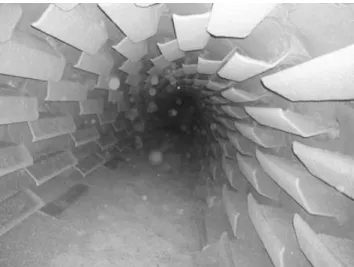
The experimental data of this work were obtained in an industrial rotary dryer of the Copebras Fertilizer Company, located in Catalão, state of Goias, Center-west of Brazil. This dryer is 30 m long, with an internal diameter of 3 m with a capacity of 120 tons per hour. The inclination angle is 2.5°. The flights are of the 3-segment type with the dimensions of 220 x 190 x 50 mm. The angles between the segments of the flights are: 90° between the side and the third segment, 145° between the third and the second segment, and 125° between the second and the first segment. The hot air enters the dryer in concurrent flow with the solids. The flights in the dryer are shown in Figure 4.
The measurements of temperature (dry and wet bulb) were carried out with thermocouples. The solid moisture content was determined by an oven method at 100oC over 24h.
Measurements of the Dynamic Friction Coefficient
Figure 4: Internal view of the industrial rotary dryer used in the present work
Figure 5: Illustrative pictures of the methodology used to measure the characteristic angle
RESULTS AND DISCUSSIONS
Fluid Dynamic Results
Dynamic Coefficient of Friction
Figure 6 shows the results of the dynamic friction coefficient (μ) of GTSP particles as a function of the flight angular position, obtained from the experimental measurements and those that were calculated from Equation (1).
It is clear that the dynamic coefficient of friction was independent of the flight angular position and this result is in agreement with data reported in the literature (Britton et al., 2006; Revol et al., 2001). The 95% statistical confidence interval for the GTSP dynamic friction coefficient is (0.731; 0.761), with an average value of 0.746.
This value was used to calculate the dynamic angle of repose and then evaluate the flight holdup for any angular position, using the previously shown equations.
Material Holdup on the Flight and Length of Fall of Particles
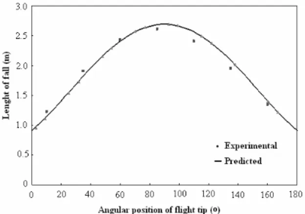
Figure 7 shows the comparison between the holdup measured in the industrial dryer for each flight angular position and the result obtained by the equations previously shown (Eq. 2 to Eq. 38). Figure 8 shows the experimental data of the length of particle fall and the predictions from Eq. (39).
It is interesting to observe in Figure 7 that the flight used in this dryer (three-segment) carries the solids to an angular position of 125o, thereby promoting a good distribution of the material in the sectional area of the drum.
The results of the length of fall (Figure 8) were employed to calculate the average length of particle fall, Y (Eq. 40), and the average fall angle (θ). The obtained values were, respectively, Y = 2.06 m and
θ = 53.7°.
The results presented in Figures 7 and 8 show that the equations obtained for the load prediction in the flights by Revol et al. (2001) and for the particle’s length of fall by Glikin (1978) allow precise estimations. This fact confirms their potential use for the prediction of solids cascading in industrial rotary dryers.
Residence Time
The residence time was measured in the industrial dryer using tracers (colored GTSP particles). Table 1 shows the comparison between the residence time obtained experimentally and that calculated from Equation 41. These results were obtained at two different drum rotation speeds (3.5 rpm and 4.2 rpm). The average deviation between experimental and calculated values was of 6%.
The results shown in Table 1 indicate that the Friedman and Marshall (1949) equation with parameters fitted by Arruda (2007) can predict satisfactorily the experimental data on residence time in industrial rotary dryers.
Drying Results
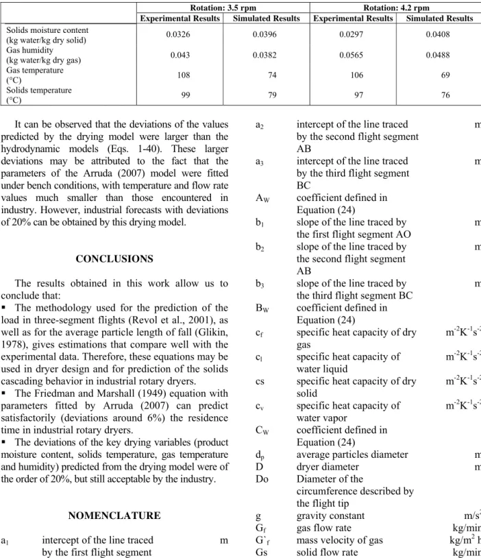
Table 2 compares the results of simulation using the drying model (Eq. 42 -49) to experimental data for the four outlet variables (solid moisture content, gas humidity, gas temperature and solid temperature) obtained from two experiments carried out at two different rotation speeds (3.5 rpm and 4.2 rpm). Following the same variable order, the average deviations between these experimental and simulated data were: 29.4 %, 12.4 %, 33.2 % and 20.9 %.
Figure 7: Variation of holdup of flights with the angular position of the flight tip (θ)
Table 1: Residence time: experimental data and values predicted by Equation 41.
Residence Time (min) 3.5 rpm Residence Time (min) 4.2 rpm
Experimental data 13.1 12.0
Predicted value (Eq. 41) 14.3 12.4
Table 2: Experimental and calculated drying results for the four outlet variables.
Rotation: 3.5 rpm Rotation: 4.2 rpm
Experimental Results Simulated Results Experimental Results Simulated Results
Solids moisture content
(kg water/kg dry solid) 0.0326 0.0396 0.0297 0.0408
Gas humidity
(kg water/kg dry gas) 0.043 0.0382 0.0565 0.0488
Gas temperature
(°C) 108 74 106 69
Solids temperature
(°C) 99 79 97 76
It can be observed that the deviations of the values predicted by the drying model were larger than the hydrodynamic models (Eqs. 1-40). These larger deviations may be attributed to the fact that the parameters of the Arruda (2007) model were fitted under bench conditions, with temperature and flow rate values much smaller than those encountered in industry. However, industrial forecasts with deviations of 20% can be obtained by this drying model.
CONCLUSIONS
The results obtained in this work allow us to conclude that:
The methodology used for the prediction of the load in three-segment flights (Revol et al., 2001), as well as for the average particle length of fall (Glikin, 1978), gives estimations that compare well with the experimental data. Therefore, these equations may be used in dryer design and for prediction of the solids cascading behavior in industrial rotary dryers. The Friedman and Marshall (1949) equation with parameters fitted by Arruda (2007) can predict satisfactorily (deviations around 6%) the residence time in industrial rotary dryers.
The deviations of the key drying variables (product moisture content, solids temperature, gas temperature and humidity) predicted from the drying model were of the order of 20%, but still acceptable by the industry.
NOMENCLATURE
a1 intercept of the line traced by the first flight segment AO
m
a2 intercept of the line traced by the second flight segment AB
m
a3 intercept of the line traced by the third flight segment BC
m
AW coefficient defined in Equation (24)
b1 slope of the line traced by the first flight segment AO
m
b2 slope of the line traced by the second flight segment AB
m
b3 slope of the line traced by the third flight segment BC
m
BW coefficient defined in Equation (24)
cf specific heat capacity of dry gas
m-2K-1s-2 cl specific heat capacity of
water liquid
m-2K-1s-2 cs specific heat capacity of dry
solid
m-2K-1s-2 cv specific heat capacity of
water vapor
m-2K-1s-2 CW coefficient defined in
Equation (24)
dp average particles diameter m
D dryer diameter m
Do Diameter of the
circumference described by the flight tip
g gravity constant m/s2
h*(0) material holdup when the flights are at the beginning of a revolution
kg
H dryer holdup kg
K constant kinetic of drying s-0.424 L´´ length of the third segment m L’ length of the second
segment
m
L length of the first segment m
Lt dryer length, m
M solids moisture content kg of water/kg of dry solid Mo initial moisture of solids kg of water/kg of dry solid M* equilibrium moisture of the
solids
kg of water/kg of dry solid MR dimensionless moisture of
solids
-N number of flights
-NR number of rotations per minute,
rpm
R dryer radius m
R0 distance from the flight edge to the dryer center
m
Rw drying rate s-1
RH relative humidity
-S transversal section area, occupied by the flight solids
m2 Tamb ambient temperature oC
Tf gas temperature oC
Ts solid temperature oC
t Time s
UVA overall volumetric heat transfer coefficient
kWm-3oC-1 Up heat loss coefficient kWm-2oC-1
V volume of dryer m3
W absolute air humidity kg of water vapor/kg of dry air X abscissa in the coordinate
set centered on the flight tip
m
xA, B, C abscissa of the points A, B and C, respectively
m
xW abscissa of point W, at the intersection of the powder level with the wall
m
X abscissa in the coordinate set centered on the drum axis
m
X0 abscissa of the flight tip in the in the coordinate set centered on the drum axis
m
y ordinate in the coordinate set centered on the flight tip
m
yA, B, C ordinate of the points A, B m
and C, respectively yW ordinate of point W, at the
intersection of the powder level with the wall
m
Y ordinate in the coordinate set centered on the drum axis
m
Y0 ordinate of the flight tip in the coordinate set centered on the drum axis
m
q
Y average length of fall m
α slope of dryer rad.
αA angle between first and second segments in flights of three segments
radians
αB angle between second and third segments in flights of three segments
radians
β angle defined by Equation (29)
δ angle of the coordinate set centered on the flight tip with the coordinate set centered on the drum axis (the angle shown in Figure 2 is negative)
radians
γ angle of the powder level with the first flight segment OA
radian
s
ρ particle density kg/m3
φ dynamic angle of repose radians ω angular rotation speed of the
drum
radians/s
τ average residence time min θ angular position of the flight
tip
radians
μ dynamic coefficient of friction
-REFERENCES
Arruda, E. B., Comparação do Desempenho do Secador Roto-Fluidizado com o Secador Rotatório Convencional: Secagem de Fertilizantes. Tese de Doutorado, Programa de Pós-Graduação em Engenharia Química, Universidade Federal de Uberlândia (2007).
Baker, C. G. J., Cascading Rotary Dryers, in Advances in Drying, vol.1: Mujumdar, A. S. (ed) (Hemisphere, New York, USA), p 1-51 (1983). Baker, C. G. J., The Design of Flights in Cascading
Britton, P. F., Sheehan, M. E. and Schneider, P. A., A Physical Description of Solids Transport in Flighted Rotary Dryers. Powder Technology, 165, 153-160 (2006).
Friedman, S. J. and Marshal, W. R., Studies in rotary drying, Chemical Engineering Progress, 45, 482-573 (1949).
Glikin, P. G., Transport of Solids Through Flighted Rotation Drums, Trans IChemE, 56, 120-126 (1978).
Kelly, J. J. and O'Donnell J. P., 1977, Residence Time Model for Rotary Drums. Trans IChemE, 55, 243-252 (1977).
Kemp, I. C., Comparison of Particles Motion Correlations For Cascading Rotary Dryers, Proceedings of the 14th International Drying Symposium (IDS), São Paulo, Brazil, B, 790-797 (2004).
Lisboa, M. H., Vitorino, D. S., Delaiba, W. B., Finzer, J. R. D. and Barrozo, M. A. S., A Study of Particle Motion in Rotary Dryer, Brazilian Journal of Chemical Engineering, 24, 3, 365-374 (2007).
Miller, C. O., Smith, B. A., Schuette, Factor Influencing the Operation of Rotary Dryers. Trans AIChE, 38, 841 (1942).
Revol, D., Briens, C. L. E and Chabagno, J. M., The Design of Flights in Rotary Dryers, Powder Technology, 121, 230-238 (2001).
Schofield. F. R. and Glikin P. G., Rotary Coolers for Granular Fertilizer, Chemical and Process Eng. Resources, 40, 183 (1962).