Inluence of Pushing and Pulling the Electrode Procedure and Addition of Second Layer of
Welding on the Wear in Hardfacing of Fe-Cr-C
Romulo Poderoso Rautaa, Samuel Filgueiras Rodriguesa,b*, Valdemar Silva Leala, Gedeon Silva Reisa,
Clodualdo Aranas Jrb, Valtair Antônio Ferraresic
Received: March 18, 2016; Revised: June 08, 2016; Accepted: August 20, 2016
The aim of this work is evaluate the inluence of welding conditions on abrasive wear resistance in coating of Fe-Cr-C. The metal base used in this investigation was the steel SAE 1020 and as welded metal the selfshilded tubular wires of Fe-Cr-C with 1.6 mm of diameter. The welding parameter such as amperage, voltage, welding speed, wire feed speed and the distance between the point and samples were kept constant by varying the electrode inclination and the number of layers deposited. These resulted in four diferent weld conditions: pulling and pushing the weld pool and hardfacing formed with 1 end 2 layers. Their inluences on dilution, microhardness and microstructure were evaluated and correlated with the abrasive wear according to the standard tests methods for abrasion measurements through the usage of dry sand/rubber wheel apparatus, ASTM G-65-04. The results showed that the wear resistance of the four diferent conditions was afected by dilution, microstructure morphology and carbide volume fraction. The best conditions for hardfacing deposition were for pushing the torch and two layers added.
Keywords: Abrasive wear, hardfacing, microstructure
* e-mail: [email protected]
1. Introduction
In maintenance, the weld process can be used as a tool to reduce the number of corrective shutdowns and increase the availability of equipment for operation. With the application of weld, critical areas of some equipment can be hardfaced by applying alloys with improved wear resistance thereby reducing the number of stoppages.
The study of the factors which inluence the weld wear resistance of applied metals on some equipment contributes to improve the quality of commercial alloys used for this purpose. Thus, welding processes application have been increasing for maintenance purposes and more engineering departments in companies have used this tool for equipment projects that will be subjected to severe wear conditions. An ordinary method against abrasive wear on metals, technically referred as hardfacing, is the application of a special alloy on a metal surface subjected to wear process by the deposition of weld beads. This method is currently being used quite efectively1-3.
The hardfacing is the application of a hard metal with considerable wear resistant on the surface of a component by
welding, metallization or combination of welding processes with the aim to reduce the material loss by abrasion, impact, erosion, surface slip and cavitation4,5. The abrasive wear can be cause by high and low stresses6. For the irst one, the abrasive wear occurs when the surface of a component is subjected to a constant contact with a granulated material low. For the second one, the wear occurs when particles is forced to pass under high pressure through some narrow space promoting the forced contact between these particles and part of the equipment. For low stresses abrasion, alloys containing chromium carbides are the most suitable, whereas in the case of high stresses abrasion, it is recommended to use austenitic-martensitic alloy, martensitic steels and some alloys which form small carbides, i.e. chromium carbide7,8.
The alloy microstructure for hardfacing application consists of a combination of carbide in a high hardness austenitic matrix providing abrasion resistance to low and high stresses9. However, under impact conditions, such as crushers, mills, or intersections railway these alloys become less efective. In this case, it is very important to combine the wear resistance and impact with the commitment to select alloys or working techniques that promote these both functions. Talking in terms of working techniques, the application of
aPrograma de Pós-graduação em Engenharia de Materiais - PPGEM, Department of Mechanic and
Materials, Federal Institute of Education, Science and Technology of Maranhão - IFMA, Av. Getúlio Vargas, nº 04, Monte Castelo, 65030-005, São Luís, MA, Brazil
bDepartment of Materials Engineering, McGill University, Wong Building, 3610, University St. H3A
2B2, Montreal, Quebec, Canada
cDepartment of Mechanic Engineering, Federal University of Uberlâdia, Av. João Naves de Ávila, 212,
Rauta et al.
1194 Materials Research
hardfacing welding by tubular wire has shown the high capacity to produce layers free of defects and has been greatly applied in the industry. Among the other processes, this technique has been acquiring reasonable preference due to its versatility combined with high productivity10-12.
It is well known that the abrasive wear resistance is strongly inluenced by the characteristics of the hardfacing such as dilution, hardness and microstructure. Therefore, the wear can be discussed based on these characteristics. In general, the commonly alloys used in order to prevent the abrasive wear belong to the Fe-Cr-C system due to their low cost and easy way of application. Low dilution is desired for low inluence on hardfacing composition and inal properties avoiding contamination from the metal base13. For this type of alloy, these characteristics are variable and depend on electrode inclination and number of deposited layers.
Within the context above, the aim of this work was to investigate the efect of electrode inclination in 15 degree for two diferent situations on the abrasive wear resistance, pushing and pulling and moreover the efect of layers quantity on a SAE 1020 steel.
2. Materials and methods
2.1.Welding procedure
The welds were performed by using universal multiprocess source 600, a wire feeder BMI STA120, a torch cooled by water, and a coordinate table whose function was to shift the torch and keeping the welding parameters constant. For added metal or coating material, it was used a tubular wire selfshilded 1.6 mm in diameter whose chemical composition is shown in Table 1.
Table 1: Chemical composition and hardness of the tubular wire
Wire Hardness
(HRC)
Composition [%]
C Cr Mn Si
FeCrC 59 to 61 4.11 23.1 0.52 0.2
As metal base for preliminary tests and application of hardfacing material, ABNT 1020 carbon steel plates were used in dimensions of 200x40x12 mm.
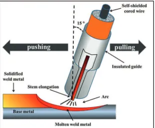
To investigate the inluence of the inclination by “pulling”, the electrode was inclined at 15 degrees and the direction of welding occurred pulling the weld pool. To “pushing”, the electrode was kept at 15 degrees and the direction of welding was given by pushing the weld pool. A schematic detail of this of theses selected process parameters are shown in Figure 1. In both cases the welding direction was the same, but the torch inclination directions were given in opposite order. Moreover, to study the inluence on the
quantity of layers, “layer 1” means that the hardfacing was performed in order to form just one layer of weld on base metal, and “layer 2”, one more weld layer was added on the previous one already formed. For the last two conditions the electrode was kept perpendicular to the metal base surface and all other parameters listed in Table 2 remained constant.
Figure 1: Schematic detail of the procedures “pushing” and “pulling” the torch with electrode inclined at 15 degree.
Table 2: Welding Parameters
Wire speed feeding 7,6 m/min.
Weld speed 475 cm/min.
Voltage 26 Volts
Current 315 Amperes
DBEM* 25 mm
*Distance between electrode and metal.
2.2. Samples preparation
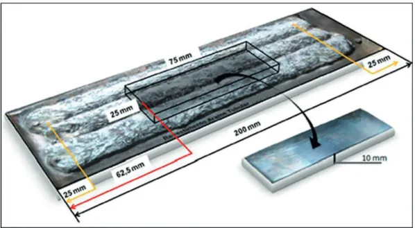
The samples for wear and hardness measurement were taken from the central region of the welded plates. The hardfacing were rectiied on surface until appear uniformed to obtain the standardized dimensions (25 x 75 x 10 mm) according to ASTM G65-0414. For each welding condition,
samples were also taken to measure the weld bead dilution. They were prepared by cutting the cross section of the welded bar, whose section was polished and etched with Nital during 10 seconds, thereby highlighting the edges of the weld beads.
Figure 2: Scheme of the sample geometry and selected area for microhardness and wear properties tests15.
2.3. Wear tests
Wear tests were performed in an abrasion machine using a rubber wheel under dry condition constructed according to ASTM 65-04, shown in Figure 3. This equipment is recommended for abrasive wear simulation under low stresses (Test type B following the standard ASTM G65-00)14. Table 3 shows the abrasion tests
parameters according to the followed standard. The wears were evaluated in terms of the specimens weight loss by comparing the weight before and after the test on an electronic weighing machine with resolution of 10-5 g.
Figure 3: Rubber wheel abrasion resistance machine used to simulating the low stress abrasion.
Table 3: Abrasion tests parameters according to the standard ASTM 65-04.
Disk Dimension 12.7 x 228 mm
Rubber wheel hardness / thickness 60 Shore A / 12.7 mm Brazilian standard n° 100 for sand 0.15 mm
Disk rotation 200 RPM
Tests time 15 min (5 min pre-loading
and 10 min of wear)
Load 130 N
Travel distance 1436 m
For dilution veriication, the samples were photographed with a digital camera and analyzed by Image J software. This analyses allowed data evaluation necessary to calculate the weld bead dilution, such as: Reinforcing area (Sad), molten area (Sfund), reinforcement height (Ref), penetration (Pn) and width (L), as shown in Figure 4.
Figure 4: Weld bead image on a layer and the components to
calculate the dilution6.
The dilution calculation was done by the relationship between the welded area and the total area of the weld bead, according to equation 1.
( )
Dilution
S
S
S
1
ad fund
fund
Rauta et al.
1196 Materials Research
The microhardness was obtained following the standard NBR 6672.
The microstructures images were obtained by SEM and the carbides volumetric percentage was calculated by Image pro plus software that allows, among other things, manipulate images and make statistical studies regarding to the phases presented.
3. Results and Discussion
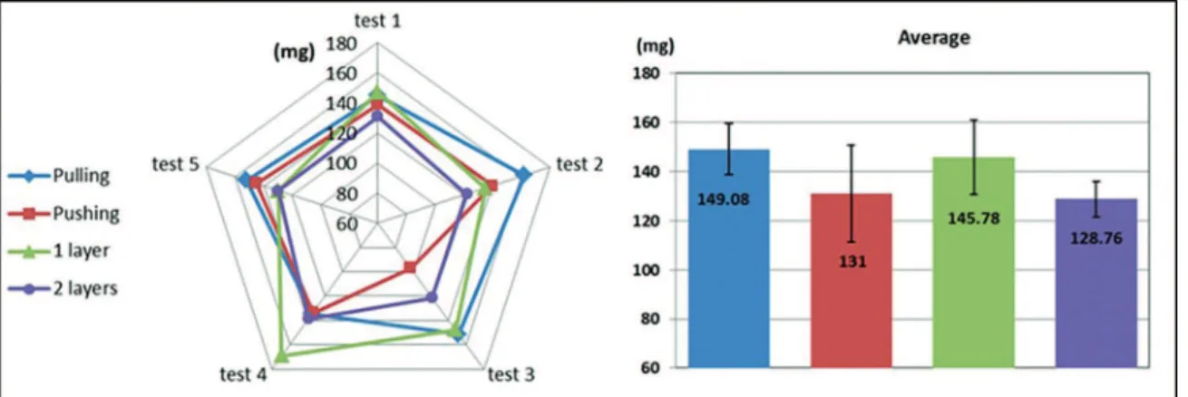
Figures 5 and 6 show the results of weight loss and dilution respectively considering the inluence of pulling and pushing weld pool, one layer and two layers of hardfacing deposited on the metal.
It is observed that for pulling the weld pool procedure, there were higher weight loss and dilution than for pushing the weld pool. The same behavior occurred for the one layer of hardfacing deposited showing more weight loss and dilution than for two deposited hardfacing on the metal base. The highest wear occurs in situations of higher dilution as well as higher heat input, contributing for higher weight loss for low stress abrasive condition for Fe-Cr-C deposits which sufered considerable dilution. When there is high degree of mixing between the metal base and added metal,
which occurred in the case of pulling the torch due to higher dilution, weld metal properties are closer to the metal base, worsening the quality of hardfacing.
According to Buchely et al.16, the wear in the irst layers is often greater than in subsequent layers. One second layer strongly contribute to low dilution whereas the second layer is formed on the welded metal itself and is expected to reduce contamination from metal base with one layer separating both. It was veriied that the application of second layer improved the hardfacing wear resistance in terms of weight loss and this is in accordance with previous investigations17.
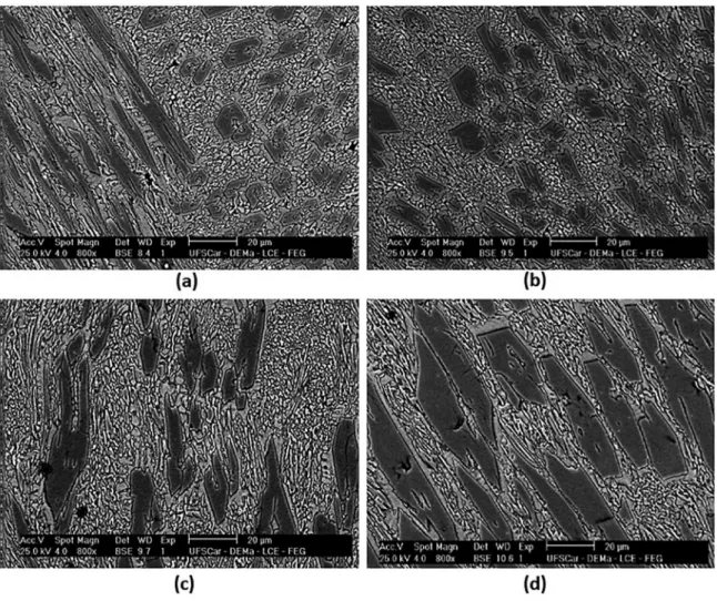
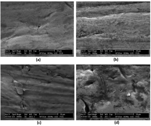
Bear in mind that when evaluating the microstructure, the hardness of the phases as well as the quantiication of them and the morphology of the precipitates are important factors that must be evaluated in order to study the abrasive wear. Diferent morphologies and quantities of those precipitates rounded by eutectic matrix are presented in Figure 7.
The microstructures shown a considerably amount of primary carbides, M7C3 type (darker region) conirmed by FactSage calculation using FSteel data base, Figure 8, and later by EDX. These carbides are involved by a light region named eutectic matrix. It is noteworthy in Figure 7(a) for pulling procedure, that the eutectic matrix is formed by small carbides and the primary M7C3 type carbide are presented in
Figure 5: Weight loss of the samples subjected to abrasion tests
Figure 7: SEM of the Fe-Cr-C hardfacing for (a) pulling the torch, (b) pushing the torch, (c) one deposited layer and (d) two deposited layers.
elongated shapes as well as in compact forms (dark phase). It is important to emphasize that the elongated shape can exceed 70 µm in length and compact ones present larger sizes close to 20 µm. In Figure 7(b) for pushing procedure, the microstructure is quite similar to the irst one but without the presence of elongated carbides and predominance of compact carbides and in more quantity. Figure 7(c) for one layer deposited, there is a large area for the eutectic matrix that is formed by small precipitates carbides and homogeneously dissolved in an austenitic phase (light phase). Furthermore, the dark phases formed by primary carbides are in irregularly shape. In Figure 7(d) for two deposited layers, it is observed high proportion of large compact carbides that can exceed 70 µm in length.
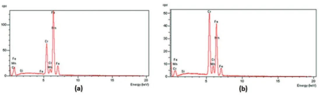
EDS technique was applied on eutectic matrix and on the primary carbides in order to identify the elements pertaining to these phases. Figures 9(a) and (b) display the chemical analysis of the eutectic matrix and primary carbides, respectively. On eutectic matrix, Fe content is greater however, it is noted the presence of Mn and Cr, which indicates small amount of carbides of these elements present in the matrix. On the primary carbides region, peaks of Cr, Fe and Mn are
Figure 8: Equilibrium diagram for the FeCrC wire used as hardfacing
added metal.
Rauta et al.
1198 Materials Research
Figure 9: EDS of the Fe-Cr-C hardfacing on (a) eutectic matrix and (b) primary carbides.
By X-ray difraction pattern on the welded sample with two layers, Figure 10, it can be noted that the predominant carbides Cr7C3 type present a peak of 62.50%, while the presence of Fe7C3 and Mn7C3 types are limited to peaks up to 33.33%. The EDX pattern for the others three conditions analyze here is not shown but they presented similar parameters as for two layers with slight diferences that can be neglected.
During the analysis made so far, worth mansion that the microstructures of the samples are formed by the same phases, carbides 56.82%Cr7C3-41.95%Fe7C3-1.23%Mn7C3 (darker phase) and an eutectic phase and small precipitates of carbides, however, with diferences in morphology, amount and size of these precipitates. These contributed decisively to the wear diferences found on the four conditions.
Figure 10: EDX of the welded sample containing two deposited layers (coating surface).
Figure 11: Microhardness, left Y axe, of the samples under the
four diferent conditions and their corresponding Carbide volume
fraction, right Y axe.
Additionally, microhardness test on the eutectic matrix and primary carbides volume fraction calculation were done in order to compare and make correlation between the weight loss, dilution percentage and microstructures. 6 microhardness measurements were done on each sample and 10 images were used to calculate the volume fraction of carbides from each sample. Figure 11 displays the microhardness average values on left Y axe and the carbide volume fraction average values on right Y axe from each of the four conditions applied
in this research. It can be seen that, pushing and 2 layers presented higher values of microhardness as well as carbide volume fraction. Whereas the expected value for the isolated austenitic phase microhardness is 350 HV17, higher values obtained for the four experimental conditions indicates that the penetrator has also reached the carbides. These values are in agreement with the weight loss and dilution. It can be seen that the condition with 02 layers showed a greater amount of carbides, about 38.7%, conirming the morphology presented in Figure 7. It can be inferred that, welds presenting elevated quantity of eutectic matrix and lower carbide volume fraction are always subjected to greater wear.
Figure 12: Wear trails for conditions of (a) pulling the torch, (b) pushing the torch, (c) one deposited layer and (d) two deposited layers. welded layer, Figure 12(c), it can be seen deep wear furrows.
For two added weld layers, Figure 12(d), it is remarkable the absence of wear trails. This is probably due to the large amount of compact carbide and well supported by the matrix preventing the action of continuous coating weigh loss.
In this research, only small changes in chemical composition and microconstituents coatings happened due to the four welding conditions, however, the size, shape, distribution and amount of microconstituents are directed related to the variation of welding conditions. In this manner, the mechanisms of abrasive wear conditions present in pushing and pulling the weld bead as well as for one and two deposited layers can be explained based on, for example, the amount of exposed eutectic matrix to abrasive particles and moreover the amount and morphology of the carbides resulting from each experimental condition.
4.Conclusions
The four techniques applied here have signiicant inluence on the wear resistance for the low stresses abrasive tests on Fe-Cr-C hardfacing.
The wears were lower for the conditions when the torch was pushed and two layers were deposited. These were favored for the low dilution and the presence of more compacted primary carbides.
The microstructure proved to be the main factor of evaluation to investigate the wear resitence under the four conditions imposed here. This microstructure is directly resulted from the amount, morphology and hardness of M7C3 carbides type.
The main wear mechanism found was to microfurrow presented mainly under the pulling the weld bead and with just one deposited layer.
5. Acknowledgements
Rauta et al.
1200 Materials Research
6. References
1. Ramalingam S, Wright PK. Abrasive wear in machining:
experiment with materials of controlled microstructure. Journal of Engineering Materials and Technology. 1981;103(2):151-156.
2. Park KH, Kwon PY. Flank wear of multi-layer coated tool. Wear. 2011;270(11-12):771-780.
3. Cardoso PHS, Israel CL, Strohaecker TR. Abrasive wear in
Autempered Ductile Irons: A comparison with white cast irons.
Wear. 2014;313(1-2):29-33.
4. Henderson JL, Bulloch JH. Alloy classiication of hardfacing
materials. International Journal of Pressure Vessels and Piping.
1991;47(2):127-158.
5. Buchanan VE, Shipway PH, McCartney DG. Microstructure and abrasive wear behavior of shielded metal arc welding hardfacings used in the sugarcane industry. Wear. 2007;263(1-6):99-110.
6. Santos MB, Labiapari WS, Ardila MAN, da Silva WM Jr, de Mello JDB. Abrasion-corrosion: New insights from force
measurements. Wear. 2015;332-333:1206-1214.
7. Liu C, Leyland A, Bi Q, Matthews A. Corrosion resistance of multi-layered plasma-assisted physical vapour deposition TiN and CrN
coatings. Surface and Coatings Technology. 2001;141(2-3):164–173.
8. Ahn SH, Choi YS, Kim JG, Han JG. A study on corrosion resistance characteristics of PVD Cr-N coated steels by
electrochemical method. Surface and Coatings Technology.
2002;150(2-3):319-326.
9. Zum Gahr KH, ed. Microstructure and Wear of Materials.
Amsterdam: Elsevier; 1987. 560 p.
10. Badisch E, Katsich C, Winkelmann H, Franek F, Roy M. Wear behavior of hardfaced Fe-Cr-C alloy and austenitic steel under 2-body and 3-body conditions at elevated temperature. Tribology International. 2010;43(7):1234-1244.
11. Bergman F, Hedenqvist P, Hogmark S. The inluence of primary carbides and test parameters on abrasive and erosive wear of selected PM high speed steels. Tribology International. 1997;30(3):183-191.
12. Berns H, Fischer A. Tribological stability of metallic materials
at elevated temperatures. Wear. 1993;162-164(Part A):441-449.
13. Kannan T, Murugan N. Efect of lux cored arc welding process parameters on duplex stainless steel clad quality. Journal of Materials Processing Technology. 2006;176(1-3):230-239.
14. ASTM International. ASTM G65-04 - Standard Test Method for Measuring Abrasion Using the Dry Sand/Rubber Wheel Apparatus. West Conshohocken: ASTM International; 2010.
15. Garcia DBC. Aplicação de revestimento duro utilizando o processo arame tubular com e sem adição de arame não energizado para diferentes tipos de consumíveis. [Dissertation]. Uberlândia:
Universidade Federal de Uberlândia; 2011.
16. Buchely MF, Gutierrez JC, León LM, Toro A. The efect of microstructure on abrasive wear of hardfacing alloys. Wear.
2005;259(1-6):52-61.