RBRH, Porto Alegre, v. 22, e22, 2017 Scientiic/Technical Article
http://dx.doi.org/10.1590/2318-0331.011716034
Macro-turbulent characteristcs of pressures in hydraulic jump formed
downstream of a stepped spillway
Características macroturbulentas das pressões em um ressalto hidráulico formado a jusante de um vertedouro em degraus
Carolina Kuhn Novakoski1, Eliane Conterato2, Marcelo Marques1, Eder Daniel Teixeira1,
Guilherme Abud Lima1 and Alexandre Mees1
1Universidade Federal do Rio Grande do Sul, Porto Alegre, RS, Brazil 2Fundação Universidade Federal de Rondônia, Porto Velho, RO, Brazil
E-mails: [email protected] (CKN), [email protected] (EC), [email protected] (MM), [email protected] (EDT), [email protected] (GAL), [email protected] (AM)
Received: March 13, 2016 - Revised: June 23, 2016 - Accepted: September 02, 2016
ABSTRACT
Stilling basins are structures built at the base of the spillway to dissipate energy, by means of a hydraulic jump. Hydraulic jump is a
turbulent phenomenon that causes large pressure luctuation in the stilling basin bottom, and can damage the sink structure through mechanisms such as fatigue, uplit pressure and cavitation. The use of stepped spillways allows the dissipation of a parcel of the energy
while the water falls by the spillway, allowing a reduction in the stilling basin’s dimensions and cost. The present article presents the
analysis of the longitudinal distribution of mean pressure, pressure luctuations, skewness coeficient and kurtosis coeficient, derived
from tests on physical hydraulic models. Pressure values measured in a stilling basin downstream of a stepped spillway (for Froude numbers between 5 and 8) were compared with data observed in a stilling basin downstream of a smooth spillway with a radius of concordance between the chute and the basin (for Froude numbers between 4.5 and 10). The results of these studies show that the
mean pressures and the pressure luctuation observed in the stilling basin downstream of stepped spillway present maximum values at
the spillway’s closest point, differing, thus, from those at the smooth spillway. The longitudinal distribution of skewness and kurtosis
coeficients enabled to deine the positions for low detachment start, roller ending and as well as the ending of the inluence of the hydraulic jump over the low.
Keywords: Stepped spillway; Stilling basin; Hydraulic jump.
RESUMO
A bacia de dissipação tem como inalidade dissipar, através de ressalto hidráulico, a energia do escoamento junto à base do vertedouro. Por ser um fenômeno turbulento que provoca amplas lutuações de pressão junto ao fundo da bacia, o ressalto hidráulico pode
comprometer a estrutura do dissipador por mecanismos como fadiga, subpressão e cavitação. A utilização de vertedouros em degraus
permite a dissipação de uma parte da energia ainda durante o escoamento da água pela calha, o que possibilita a redução das dimensões e do custo da estrutura da bacia de dissipação. O presente artigo apresenta a análise das distribuições longitudinais da pressão média, das lutuações de pressão e dos coeicientes de assimetria e curtose, oriundas de ensaios realizados em modelos físicos hidráulicos. Foi feita uma comparação das características das pressões obtidas em uma bacia de dissipação a jusante de um vertedouro em degraus
(para números de Froude entre 5 e 8) com dados observados em uma bacia de dissipação a jusante de um vertedouro de calha lisa, com
raio de concordância entre a calha e a bacia (para números de Froude compreendidos entre 4,5 e 10). A partir dessa análise pode-se concluir que, diferentemente do ocorrido na bacia de dissipação com calha lisa, as pressões médias e lutuações de pressão observadas na bacia de dissipação a jusante de calha em degraus tem seu máximo no ponto mais próximo ao pé do vertedouro. O desenvolvimento longitudinal dos coeicientes de assimetria e curtose possibilitaram determinar as posições de início do descolamento do escoamento, de im do rolo e de im da inluência do ressalto hidráulico no escoamento.
the Tozzi (1992) experiments indicated a relation between the residual energies in smooth chutes and stepped chutes ranging from 40 to 66% and, for the studies of Sanagiotto (2003), energy dissipation in stepped chutes in relation to smooth chutes reached values between 45 and 94%.
According to Peterka (1957), a stilling basin where a
hydraulic jump is formed downstream of a spillway is classiied
as a type I basin. According to Schulz et al. (2015), the hydraulic jump can be described as the result of a shock between the
subcritical and supercritical lows, resulting in a zone with circular
movements (roller). This phenomenon generates great swells,
luctuations of pressure and velocity and can cause damage to
the structure. The knowledge of the geometric characteristics of the hydraulic jump is fundamental for the elaboration of the design of the dissipation structures. One of the most studied geometric characteristics is the length of the hydraulic jump due to a high level of imprecision. Peterka (1957) deine the end of the hydraulic jump as the section immediately downstream of the roller. Marques, Drapeau and Verrette (1997) and Teixeira (2003) devised the Equations 1 and 2 for calculating the length of the hydraulic jump, respectively. For the length of the roller, Marques, Drapeau and Verrete et al. (1997) devised the Equation 3.
Other parameters that must be known for an adequate design of the dissipation structures are the longitudinal distributions
of mean pressure, pressure luctuation, skewness and kurtosis coeficients. Marques, Drapeau and Verrette (1997) presented experimental results obtained for these parameters measured in a stilling basin downstream of smooth chute spillway with a radius of concordance between the spillway and the channel bottom. In this study the hydraulic jump was positioned so that its beginning coincided with the point of tangency between the radius of concordance of the spillway and the bottom of the channel. In this same line of positioning of the hydraulic jump, other studies were developed, such as Mees (2008), who studied the effects of the hydraulic jump in a type I stilling basin for low numbers of Froude, and Conterato (2014), who studied the effects of the phenomenon in a stilling basin with terminal sill downstream of a stepped spillway.
The present paper presents the results observed in a stilling basin downstream of a stepped spillway and compares them with those observed by Marques, Drapeau and Verrette (1997).
( )
8.5
j l r
L = Y−Y (1)
( )
8.0
j l r
L = Y−Y (2)
of smooth chute.
Physical model of the stilling basin downstream of a stepped spillway
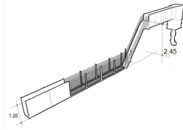
The research was developed in a reduced partial model of a stepped spillway with downstream stilling basin. The model consists of a chute with a slope of 1V: 0.75H (53.13), height of 2.45 m, width of 0.40 m and has steps with a height of 6 cm. Downstream of the chute there is a horizontal channel 1.20 m high, approximately 8 m long and 0.40 m wide. To allow visualization
of the low, 5 m of channel length have acrylic walls. Downstream of the channel, a vertical shutter-type loodgate combined with a graduated scale piezometric tube allow level control and veriication.
Upstream of the stepped chute, a 5 m long segment was built as
well as a small reservoir to tranquilize the low. The channel admits a speciic low of approximately 0.3 m2/s, which corresponds to a depth of water of approximately 0.27 m. A simpliied schematic
of the model is shown in Figure 1.
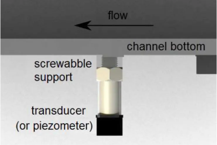
To measure the pressures, transducers of the brand Sitron, model SP96 were used, installed in 20 distinct points, distanced from the end of the stepped chute. The transducers were installed with a screwabble support placed under the bottom of the channel, thus possible distortion effects of the pressure signal due to the connection with hoses are eliminated. Figure 2 shows a schematic of the installation of the transducers.
Of the 20 transducers used, 10 have a working range of -1.5 to 1.5 mH2O and 10 have a range of -1.5 to 3.0 mH2O. Transducer signals were passed to na analog digital converter of the brand National Instruments, model USB-6225, with digital resolution of 16 bits and admissible voltage range of -10 to 10 V. All the tests were carried out with a duration of 15 minutes and a frequency of 128 Hz, which generated 115200 sample points. Table 1 shows the distances, from the end of the stepped chute, and the transducer range for each tapping point.
Physical model of the stilling basin downstream of smooth chute spillway
The model used by Marques, Drapeau and Verrette (1997) consists of a Creager spillway with a height of 720 mm installed in a channel with a width of 600 mm. The authors obtained the pressure data through 22 transducers of the brand Omega, model PX800-005GV, installed externally to the channel. The taps were attached to the transducers through silicone hoses of 6.4 mm in diameter and 500 mm in length, following the recommendations of Lopardo and Henning (1986). The data was obtained with 50 Hz frequency in measurements lasting 200 s.
METHODOLOGY OF TESTS
The tests carried out in the stilling basin downstream of the
stepped spillway were performed with ive different low rates: 40, 60, 80, 100 and 110 L/(s.m). The maximum low rate was limited in order to avoid channel overlow and minimum low, by the accuracy of the electromagnetic low meter, which allows measuring only lows above 40 L/s. Table 2 presents the characteristics of the tests and Figure 3 shows the parameter deinition.
(
2)
1
1 8 1
2 l r r y F
y = + − (4)
r r r v F y g =
× (5)
r r
e v y
R = ν× (6)
Where Q = low, vr = mean velocity in the section of the fast
conjugate height;Fr = Froude number of the supercritical low of
the hydraulic jump; Re = Reynolds number of the supercritical low
of the hydraulic jump; g = acceleration of gravity; ν = kinematic
viscosity of the luid.
Figure 2. Schematic of transducer installation. Table 1. Distances and ranges of the transducers for each pressure tapping point.
Tapping point Distance
(cm)
Transducer range (mH2O)
1 17.4 -1.5 to 3.0
2 27.4 -1.5 to 3.0
3 37.4 -1.5 to 3.0
4 53.8 -1.5 to 3.0
5 64 -1.5 to 3.0
6 73.9 -1.5 to 3.0
7 84.4 -1.5 to 3.0
8 103.8 -1.5 to 3.0
9 114 -1.5 to 3.0
10 129.2 -1.5 to 3.0
11 138.2 -1.5 to 1.5
12 169.4 -1.5 to 1.5
13 199.6 -1.5 to 1.5
14 229.4 -1.5 to 1.5
15 269.5 -15 to 1.5
16 300.5 -1.5 to 1.5
17 330.5 -1.5 to 1.5
18 365 -1.5 to 1.5
19 400 -1.5 to 1.5
20 435 -1.5 to 1.5
Figure 3. Description of parameters.
Table 2. Characteristics of the test perfomed in stilling basin downstream of a stepped spillway.
Q (L/s) yr
(mm) vr (m/s) yl (mm) Fr Re (x1000)
40 26.4 3.78 265 7.44 100
60 36.11 4.15 339 6.98 150
80 44.05 4.54 409 6.91 200
100 54.15 4.62 459 6.34 250
and Verrette (1997).
Marques, Drapeau and Verrette (1997) performed their tests, also, with free hydraulic jump. Table 3 presents the characteristics of the these tests.
MEAN PRESSURE
The mean pressure data were presented as a function of the position of the hydraulic jump according to Equation 7, as suggested by Marques, Drapeau and Verrette (1997).
x r
l r l r
P y x
f
y y y y
−
=
− − (7)
tested in the present study show a similar pattern. The values obtained for the point nearest to the spillway, where the impact of the water jet in the stilling basin occurs, are higher than those observed in Marques, Drapeau and Verrette (1997) to the same point. This fact occurs due to the presence of radius of acordance between spillway and stilling basin in the study of the
authors, which signiicantly reduces the pressure at the beginning
of the basin. After this, an abrupt reduction in pressure occurs to approximately the position of 1 (yl−yr). From this point on
the data obtained for the present study show a similar pattern to the data obtained by Marques, Drapeau and Verrette (1997), increasing with approximately the same gradient to the position of about 4 (yl−yr). This zone in which the values of the mean
pressures increase with the same gradient is represented in Figure 6 as zone 1. Thereafter, the mean pressure continues to increase, however, more smoothly, to the approximate distance of 8.5
(yl−yr) (zone 2). From this point on the values begin to oscillate
until they become practically constant (zone 3).
PRESSURE FLUCTUATION
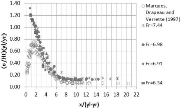
For the pressure luctuation analysis, the relation presented
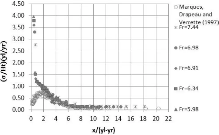
in Equation 8 was used to group the data into a single curve. Figure 7 presents the gross values obtained for the standard deviation in the tests performed and Figure 8 presents the
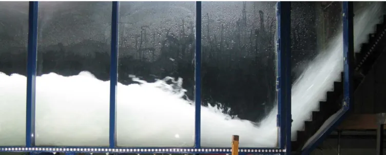
Figure 4. Runoff for the low of 80 L/s.
Table 3. Characteristics of the tests in stilling basin downstream of smooth chute spillway.
Q (L/s) Yr
(mm) Vr (m/s)
Yl
(mm) Fr
Re (x1000)
35 16 3.67 186 9.3 59
48 22 3.72 218 8.1 82
63 28 3.76 247 7.2 102
87 38 3.83 301 6.3 147
127 54 3.92 373 5.4 212
dimensionless curves obtained for pressure luctuation, according
to Equation 8, compared to those obtained by Marques, Drapeau and Verrette (1997).
x l
t r l r
y x
f
H y y y
σ
= −
(8)
Where σx = standard deviation at the point x in meters of depth of water; Ht= loss of head in the hydraulic jump.
Observing Figure 7 it shows that the standard deviation gross values increase with Froude number, ranging from about 0 to 0.35.
From Figure 8 it can be asserted that the pressure luctuation values occurring in the present study are maximum at the point
closest to the chute, then the lotation undergoes a strong reduction
to the approximate position of 1,0 (yl−yr), from that point to
the distance of about 4.0 (yl−yr) the pressure luctuation still
decreases, but more gently. After that the values tend to stabilize. Comparing with the results of Marques, Drapeau and Verrette (1997), it can be observed that, as well as the mean pressures, the
pressure luctuations obtained by the authors at points closesest
to the chute are lower than those obtained in the present study. This effect occurs due to the presence of a radius of concordance
between spillway and stilling basin in the study of Marques, Drapeau and Verrette (1997) which, in addition to the mean pressure values,
also signiicantly reduces the pressure luctuations at the beginning
of the basin. After this, the curves plotted with the data of the present study tend to meet the curves obtained by the authors, presenting very similar patterns. This encounter occurs at the approximate position of 3.0 (yl−yr). Figure 9 presents a detail
of the same curves focusing on the pressure luctuations up to
the dimensionless value of 1.4.
SKEWNESS COEFFICIENT
The analysis of the skewness coeficient of a series of
instantaneous pressures indicates how much the extreme values
inluence the mean. When the coeficient is positive, there are
more values of instantaneous pressures highter than the mean, the function is shifted to the right and the value of the mean is
elevated. Contrarily, a negative skewness coeficient indicates the
greater presence of instantaneous pressure values lower than the mean, which shifts the function to the left and causes a reduction in the mean value. According to Lopardo and Henning (1986),
negative skewness means areas of low detachment from the
Figure 5. Gross mean pressure data.
Figure 6. Mean pressure as a function of the distance of the stepped spillway compared to the mean pressure obtained in the smooth chute.
Figure 7. Gross data of standard deviation.
Figure 8. Pressure luctuation as a function of the distance of
at position x.
Figure 10 indicates that skewness values range from approximately -0.7 to 0.9, reaching maximum values at positions between 0 and 100 cm and minimum values between 100 and 300 cm.
Figure 11 shows the curves obtained for the present study. It can be observed that from the vicinity of the chute until the approximate position of 4.0 (yl−yr), the skewness coeficient
is positive and presentes the highest value in the sample. This is due to the impact of the water jet in the basin, which causes higher instantaneous pressures. According to Marques, Drapeau and Verrette. (1997), it is also at this point that the low begins to present a vertical componente to the velocity. From this point
on, according to visual observations of the low combined with
the analysis of data acquired by the cited authors, the value of the
skewness coeficient begins to reach negative values, due to the fact that the low begins to separate (detach) from the bottom of the
basin, generating lower extreme pressures. This analysis coincides with the conclusions presented by Lopardo and Henning (1986).
The minimum skewness coeficient is displayed at the position of
about 6 (yl−yr) which is the position of the end of the roller in
the hydraulic jump. At this point the vertical components of the velocity are more important, and the extreme pressures lower than the mean predominate over the higher ones. From this point on
the low tends to an equilibrium, being parallel to the bottom of the basin, so the skewness coeficient tends to a constant value, close to 0.20. The coeficient reaches this value in the position of
approximately 8 (yl−yr), and then, most points tend to stabilize
the skewness coeficient at values slightly above zero, no longer suffering the inluence of the hydraulic jump. The data obtained
by Marques, Drapeau and Verrette (1997) show a similar trend, but at the beginning of the stilling basin to the approximate position of 1.5 (yl−yr), the skewness values are higher. From that point
on, the two studies have similar curves, the points at which the
minimum values of the skewness coeficient occur and where this coeficient again reaches 0, are practically the same in both studies.
KURTOSIS COEFFICIENT
The kurtosis coeficient (k) is a dispersion coeficient that
indicates how much the values are concentrated in relation to the mean. A distribution with values that are more concentrated in relation to the mean, which makes it more tapered, presents
a kurtosis coeficient of less than three. When the coeficient is higher than three, the distribution is more lattened, presenting
less concentrated values than the mean. Equation 10 presents
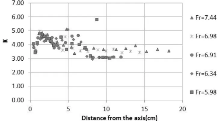
the calculation of the kurtosis coeficient. Figure 12 presents
the gross values obtained for the kurtosis coeficient in the tests
performed and Figure 13 presents the results obtained for the present study compared with the values obtained by Marques, Drapeau and Verrette (1997).
Figure 9. Detail of the pressure luctuation as a function of the
distance of the stepped spillway compared to the mean pressure obtained in the smooth chute.
Figure 10. Skewness coeficient data as a function of the (gross)
distance of the stepped spillway.
Figure 11. Distribution of skewness coeficients as a function of
Figure 12. Data on kurtosis coeficients as a function of the
(gross) distance of the stepped spillway.
( )4 4 1 i n i x
i x
P P
k
n σ
= =
− =
×
∑ (10)
Figure 12 shows that the values of the kurtosis coeficient vary approximately from 3.0 to 5.0, and a single point with a kurtosis value close to 6.0 can be observed, which may mean an error in the acquisition of the data.
From Figure 13 it can be asserted that, from the beginning of the stilling basin to the approximate position of 1 (yl−yr), the
values of the kurtosis coeficient obtained for the present work vary between the values of 3.5 and 4, differing signiicantly from
those obtained by Marques, Drapeau and Verrette (1997), which, in this range, are quite dispersed and reach much higher values. From the position of 1 (yl−yr) to approximately the position of
4 (yl−yr) the curves obtained for the present work meet those
obtained by the author with values of kurtosis coeficient close
to 4. After that point until the position of 6 (yl−yr), where the
low undergoes a detachment of the bottom tending to ind the total height of the low, the values of kurtosis coeficient found
in the present study are a little more dispersed, but still close to 4. The results from Marques, Drapeau and Verrette (1997) show a greater dispersion, reaching values close to 6. After this position, the curves resulting from both studies meet again, the values of
the kurtosis coeficient suffer a gradual reduction tending to the
value of 3.
CHARACTERISTIC POINTS OF THE HYDRAULIC JUMP
From the previous analyzes of the longitudinal distributions
of mean pressure, pressure luctuation, skewness and kurtosis coeficients, it was possible to determine some characteristic
points of the hydraulic jump and compare with those determined by Marques, Drapeau and Verrette (1997).
The highest pressure luctuation found was at the position
of approximately 0.4 (yl−yr), while the position of higher pressure
luctuation found by Marques, Drapeau and Verrette (1997) was 1.75 (yl−yr). The positions of low detachment, end of the
hydraulic jump, end of the roller and end of dissipation found for both studies were the same: 4.0 (yl−yr) for the beginning of
the low detachment, 6 (yl−yr) for the end of the roller and 8.0 (yl−yr) for the end of the hydraulic jump.
CONCLUSIONS
Through the statistical analysis of the mean pressures,
pressure luctuations and skewness and kurtosis coeficients
presented previously, it was possible to reach some conclusions. The mean pressures are maximum at the nearest point of the stepped chute, differing from the results obtained by Marques, Drapeau and Verrette (1997), for a smooth chute, due to the presence of radius of concordance between chute and stilling basin in the author’s essays. Then, the mean pressures decrease sharply and increase again with the distance, coinciding with the data obtained by Marques, Drapeau and Verrette. (1997). The pressures increase to the position of 8.0 (yl−yr), where the inluence of
the hydraulic jump ends, tending to a stabilization. This position
coincides with the end of the inluence of the hydraulic jump
obtained by Marques, Drapeau and Verrette (1997).
The pressure luctuations, as well as the mean pressures,
have their maximum at the closest point to the stepped chute, also differing from the results obtained for studies in smooth chute for the same reason, and decrease with distance. The pressure
luctuation curves obtained by the two studies show the same
tendency from the approximate position of 3 (yl−yr) on.
Analyzing the skewness coeficient, it can be perceived that the beginning of the low detachment (where the coeficient begins
to reach negative values) occurs at the approximate position of 4 (yl−yr). The end of the roller (where the skewness coeficient
reaches its minimum value) occurs approximately in the position of 6 (yl−yr), and the end of the inluence of the hydraulic jump
(where the skewness coeficient tends to a stabilization with value
close to zero) occurs at the position of about 8.5 (yl−yr). These
values are the same as those obtained by Marques, Drapeau and Verrette (1997) for the study with smooth chute.
The longitudinal distribution of the skewness and kurtosis
coeficients for a hydraulic jump formed downstream of a smooth
chute and a stepped chute are similar. The simultaneous analysis of both parameters allows to verify that the pressure data at a given
Figure 13. Distribution of kurtosis coeficients as a function of
LOPARDO, R. A.; HENNING, R. E. Efectos de las condiciones de ingreso al ressalto sobre el campo de pressiones instantâneas. In: CONGRESSO LATINO AMERICANO DE HIDRÁULICA, 12., 1986, São Paulo. São Paulo: IAHR, 1986. vol. 1, p. 116-127.
MARQUES, M. G.; DRAPEAU, J.; VERRETTE, J. L. Flutuação
de pressão em um ressalto hidráulico com baixo número de froude.
Revista Brasileira de Recursos Hídricos, v. 2, n. 2, p. 45-52, 1997.
MEES, A. A. A. Caracterização das solicitações hidrodinâmicas em bacias de dissipação por ressalto hidráulico com baixo número de froude. 2008. 157 f. Dissertação (Mestrado em Engenharia) - Programa de
Pós-Graduação em Recursos Hídricos e Saneamento Ambiental, Instituto de Pesquisas Hidráuicas, Universidade Federal do Rio
Grande do Sul, Porto Alegre, 2008.
PETERKA, A. J. Hydraulic design of stilling basins and energy dissipators. Washington: Govt. Print. Off, 1957.
SANAGIOTTO, D. Características do escoamento sobre vertedouros em degraus de declividade 1V:0,75H. 2003. 118 f. Dissertação (Mestrado
em Engenharia) - Programa de Pós-Graduação em Recursos Hídricos e Saneamento Ambiental, Instituto de Pesquisas Hidráuicas,
Universidade Federal do Rio Grande do Sul, Porto Alegre, 2003
SCHULZ, H. E.; NÓBREGA, J. D.; SIMÕES, A. L. A.; SCHULZ, H.; PORTO, R. M. Details of hydraulic jumps for design criteria
(Mestrado em Engenharia) - Programa de Pós-Graduação em Recursos Hídricos e Saneamento Ambiental, Instituto de Pesquisas Hidráuicas, Universidade Federal do Rio Grande do Sul, Porto
Alegre, 2003
TOZZI, M. J. Caracterização/comportamento de escoamento em vertedouros com paramento em degraus. 1992. 302 f. Tese (Doutorado em Hidráulica) - Universidade de São Paulo, São Paulo, 1992.
Authors contributions
Carolina Kuhn Novakoski: data collection, data analysis and article elaboration.
Eliane Conterato: article elaboration, data collection and article review.
Marcelo Marques: work orientation and data analysis.
Eder Daniel Teixeira: work orientation and data analysis.
Guilherme Abud Lima: data analysis.