Abstract
In this study, the dynamic instability of beams under tip follower forces are considered. The beam is modeled by using the geometri-cally exact, fully intrinsic beam equations which is subjected to an inclined tip follower force. Generalized differential quadrature method is employed to solve the governing equations. The effect of different parameters such as follower force inclination and magni-tude, rotating speed, the distance between the beam center of grav-ity and elastic center, and cross-sectional properties on the instabil-ity boundary of beams are examined. Numerical results reveal that the critical load of the system can be influenced or in some cases be reversed by the combination of these parameters instead of consid-ering these parameters separately. Moreover, it is shown that not-withstanding the simplicity of the equations and the method of solution, the results are very accurate and therefore the fully intrin-sic equations and the method of solution is very useful for the dy-namic solution of rotating and non-rotating beams.
Keywords
Inclined Follower Force, Fully Intrinsic Equations, Generalized Differential Quadrature Method, Dynamic Instability.
Dynamic Instability of Beams Under Tip Follower Forces
Using Geometrically Exact, Fully Intrinsic Equations
1 INTRODUCTION
The instability of structures under non-conservative forces is among the most important problems that many researchers have focused on it. Systems under non-conservative forces may be exposed to dynamic or static instabilities, but a system subjected to conservative forces may experience only the static instability. Follower forces are examples of non-conservative forces that maintain their direction in a manner that always obey the deformation curve of the beam. There are a lot of actual systems that can be modeled by follower forces. Among them, the aircraft wing subjected to the engine thrust and the cantilever pipes conveying fluids are the most important instances of systems that may be simulated by follower forces. One of the first studies that investigated the stability of
Mohammadreza Amoozgar a Hossein Shahverdi a, *
a Department of Aerospace Engineering
and Center of Excellence in Compu-tatinoal Aerospace Engineering, Amirka-bir University of Technology, Tehran, Iran. Author email:
* Corresponding author:
http://dx.doi.org/10.1590/1679-78253010
structures exposed to follower forces, as mentioned by Bolotin (1963), was the work done by Niko-lai, and after that many papers and also some books are concentrated on this topic (Bolotin (1963, 1964), Leipholz (1978), Simitses and Hodges (2006)). In the spite of all the published works, there seems that very little attention has been put on the lateral-torsional stability of rotating cantilever beams under inclined transverse follower forces. In 1952, Beck (1952) determined the dynamic in-stability of a cantilever column exposed to a tangential follower force. In this study, the follower force was a concentrated force that exactly applied at the tip of the column. Leipholz (1962) consid-ered the stability of a cantilever column under uniformly distrusted tangential follower force approx-imately. Como (1971) studied the stability of a cantilever beam subjected to a lateral tip follower force without considering the mass and inertia distribution of the beam. In this study, a concentrat-ed mass and inertia locatconcentrat-ed at the tip of the beam were includconcentrat-ed. This work has been reconsiderconcentrat-ed by Wohlhart (1971) by considering the mass and inertia distribution of the beam, and the effect of different parameters on the stability of the beam was presented. Zuo and Schreyer (1996) studied the dynamic and static instability of cantilevered beams as well as simply supported plates subject-ed to non-conservative forces. The lateral stability of a beam subjectsubject-ed to follower forces has been investigated by Detinko (2002)). In this paper, it was shown that by neglecting the slight internal and realistic external damping, the critical load of the system will be determined inaccurately. Feldt and Hermann (1974) considered the bending torsional instability of cantilever beams under tip transverse follower forces. They presented a comprehensive study on different parameters on the instability boundary of the system but the obtained results were not in agree with previously pub-lished works. The effect of shear deformation and rotary inertia on the stability of slender Euler-Bernoulli cantilever columns subjected to follower forces has been considered by Nair et al. (2002). Stability determination of a rotating cantilever subjected to dissipative, aerodynamic, and trans-verse follower forces has been investigated by Anderson (1975). In this study, the variation of criti-cal flutter load with respect to the hub radius, the rotational speed, aerodynamic load parameters and the warping rigidity has been examined, but the effect of follower force inclination angle and the mass centroid offset from the reference line has been not determined. Hodges (2001) investigated the lateral-torsional flutter of a deep cantilever beam subjected to a tip lateral follower force. In this paper, the effect of different parameters on the critical follower force has been studied. This work has been continued by adding the aerodynamic loading on the beam (Hodges and Patil (2002)). More recently, Fazelzadeh and Kazemi-Lari (2014) and Kazemi-Lari and Fazelzadeh (2015) consid-ered the stability analysis of a deep cantilever beam with transverse uniformly and partially distrib-uted follower forces. They observed that the position and magnitude of the distribdistrib-uted load can influence the stability boundary of the beam. The effect of engine thrust that may be modeled by a transverse follower force on the aeroelastic instability of wings has been considered by Hodges and Patil (2002), Amoozgar et al. (2013), Fazelzadeh et al. (2009), Mardanpour et al. (2013) and Mardanpour et al. (2014). In all these studies, it was shown that the magnitude and position of the follower force influence the stability boundary of the wing.
neither displacement nor rotation variables appear in the related partial differential equations which are stress (or strain) based formulation. These theories are called fully intrinsic theories based on the terminology of Green and Laws (1966) and Reissner (1973) and originally developed by Heg-emier and Nair (1977) and more recently reconsidered by Hodges (2003). In recent years, many researchers considered this type of beam equation to study the static and dynamic behavior of beams. Patil and Hodges (2006) studied the flight dynamic of a flexible flying wing configuration by using the fully intrinsic geometrically exact beam equations. Mardanpour and Hodges (2013) exam-ined the effect of engine on trim and aeroelastic stability of flying wing vehicles. They showed that considering the gravity can influence the stability envelope of the wing. This work has been contin-ued by considering multiple engines and time-dependent thrust effects on the aeroelastic behavior of flying wings. To the best of the author’s knowledge, the dynamic stability of rotating cantilever wings subjected to inclined follower forces by using the geometrically exact fully intrinsic beam equations have never been considered and the objective of the present paper is to consider this topic and further investigation of different parameters on the stability boundary of these beams.
Up to now, there are a number of solution methods that are used for solving the fully intrinsic beam equation. They are limited to simple discretization of the equations (Sotoudeh et al. (2010) and Mardanpour et al. (2014)), variable order finite element method (Patil and Hodges (2011)), Galerkin method (Patil and Althoff (2011)), and Chebyshev collocation method (Khaneh Masjedi and Ovesy (2014, 2015)). All these methods are successfully applied to the fully intrinsic beam equations for different problems. In this paper, an alternative method of solution called Generalized Differential Quadrature (GDQ) method will be used to solve the fully intrinsic beam equations. This method is among the easiest and efficient solution methods which can be applied directly to the partial differential equations. The differential quadrature method was first introduced by Bellman and Casti (1971). In this method, the derivative of a function at a specific point is approximated as a weighted linear summation of the values of the function at all other sampling points along the domain. Shu and Richards (1992) proposed a method to overcome the DQ drawbacks by introduc-ing the GDQ method based on the analysis of a polynomial vector space. By usintroduc-ing the GDQ meth-od, the first order derivatives are computed by a simple algebraic formulation without any limita-tion on choosing the grid points. Until now, many researchers used this method for solving various problems containing partial differential equations in fluid flow (Shu and Richards (1992), Shu et al. (1995) and Shu et al. (1996)) or in structures (Bert and Malik (1996), Du et al. (1995), Du et al. (1996), Laura and Gutierrez (1993, 1994) and Lin et al. (1994)) and the literature is overwhelmingly rich, and here only a few examples are presented. Lin et al. (1994) used the GDQ method to study the plate deflection with nonlinear boundary supports. Marzani et al. (2008) solved the non-conservative stability problems via GDQ method. Lal and Saini (2015) determined the vibration behavior of non-homogeneous orthotropic rectangular plates of bilinearly varying thickness by GDQ method. Also, a review on differential quadrature method and its applications in computational mechanics was implemented by Bert and Malik (1996). Amoozgar and Shahverdi (2016) used the generalized differential quadrature method for solving the geometrically exact fully intrinsic beam equations and showed that this numerical method is an efficient method for these type of equations.
meth-od. First, the governing equations of the system with tip follower force have been demonstrated. Then by introducing the method of solution to the governing equations, the beam bending and tor-sional modes are obtained. The effect of rotating speed, the inclination angle of the follower force, the offset of the mass centroid from the elastic axis, the ratio of the bending and torsional frequen-cies and some other parameters on the stability boundary of the wing are examined. It is found that the combination of these parameters can change the instability region of the system dramatically.
2 GOVERNING EQUATIONS
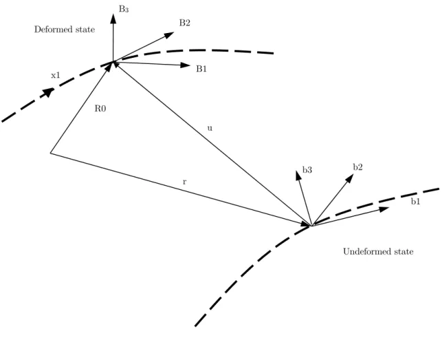
Figure 1 shows a beam with its reference coordinates in deformed and undeformed configurations which are denoted by b(x1), and B(x1,t), respectively.
Figure 1: Schematic of the beam kinematics Amoozgar and Shahverdi (2016).
0
R
andr
are the reference line position vectors in the deformed and undeformed states, re-spectively and uis the displacement vector.The nonlinear geometrically exact, fully intrinsic governing equations for the dynamics of an ini-tially curved and twisted beam undergoing large deformations in the deformed coordinate can be expressed as(Hodges (2003)):
Undeformed state Deformed state
B1 B2
b1 b2
b3 r
R0
u x1
1 1F +(k +κ)F +f = P + ΩP,
M +(k +κ)M +(e +κ)F +m = H + ΩH + VP,
V +(k +κ)V +(e + γ)Ω = γ,
Ω +(k +κ)Ω = κ,
(1)where
()
is the partial derivative with respect to x1,( )
shows the partial derivative with respectto time.
M
andF
are the internal moment and force vectors which are expressed in the matrix form.H
andP
are the generalized angular momentum and linear momentum vectors,Ω
andV
are the generalized linear and angular velocityf
andm
denote the generalized strains and curva-ture,κ
andγ
are the external moment vectors and force applied on the beam, respectively. It is noted that all above variables are in the matrix form and expressed in the deformed state except the initial curvature k wich is expressed in the undeformed configuration e1 is a vector wich itsar-rays are as bellow:
1
1 0 0
T
e
(2)The generalized strains of an isotropic beam are related to the generalized force and moment via the following constitutive equations as follows (Simitses and Hodges (2006)):
11 2 1
12 2 3 13 3 1 1 2 2 3 3 2 3
1
0
0
0
0
0
1
0
0
0
0
0
2
0
0
1
0
0
0
2
1
0
0
0
0
0
1
0
0
0
0
0
1
0
0
0
0
0
EA
F
GA
F
GA
F
M
GJ
M
M
EI
EI
(3)On the other hand, the generalized linear and angular velocities are related to the generalized linear and angular momentum through the cross-sectional inertia matrix as:
where
I
,
and
are the cross-sectional inertia matrix, the mass per unit length, and the mass center offset from the beam reference axis, respectively. The cross-sectional inertia matrix and the mass center offset vector components are:2 3
2 23
23 3
0 0
0
0
i
i
I
i
i
i
i
(5)
0
2 3
T
x
x
(6)where i2 and i3 are the cross-sectional mass moments of inertia and i23 denotes the cross-sectional product of mass moment of inertia, and
x
2 andx
3 are offsets from the reference line along the cross-section coordinates.By inserting Eqs. 3 and 4 in the fully intrinsic equations of motion (Eq. 1), the resultant equa-tions can be rearranged in a manner that the primary unknown variables will be the generalize force, moment, linear velocity and angular velocity. There will be 12 unknown variables and there-fore 12 boundary conditions are needed for solving the fully intrinsic equations of motion. In this paper, a cantilever beam with length
L
is considered and the 12 boundary conditions will be:0 0 0 0
( , )
,
( , )
,
(0, )
,
(0, )
.
F L t
F
M L t
M
V
t
V
t
(7)It is of note that, the displacements and rotations variables of the beam can be determined by the following relation in post-processing phase (Sotoudeh et al. (2010)):
,1
(
) ,
C
k
C
(8)1
(
)
T(
).
r
u
C
e
(9)where u is the displacement vector of the beam.
3 NUMERICAL SOLUTION PROCEDURE
The generalized differential quadrature method is used to solve the fully intrinsic equations. The main idea of this method is to evaluate the derivative of a function at a specific point as a weighted linear summation of all the functional values at all other points along the domain (Shu and Rich-ards (1992)). In this method, the n-th order partial derivative of a function like f(x) with respect to the space variable can be written as:
( )
( ) ( ) ( )
1
( )
( ),
1,2,...,
1
n N
n n
x i ik k
n
k
f
f
x
W
f x
n
N
x
(10)where N is the number of sampling points considered in the domain and ( )n ik
(1) (1)
(1)
( )
, ,
1,2,...., Nand
(x x )M ( )
iik
i k k
M
x
W
i k
i
k
x
(11)where
(1)
1,
( )
i N(
i k)
i i kM
x
x
x
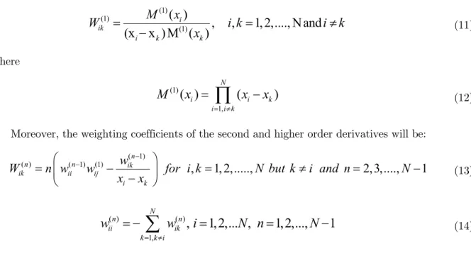
(12)Moreover, the weighting coefficients of the second and higher order derivatives will be: ( 1)
( )n ( 1) (1)n ikn
,
1,2,...,
2,3,....,
1
ik ii ij
i k
w
W
n w
w
for i k
N but k
i and n
N
x
x
(13)( ) ( )
1,
,
1,2,... ,
1,2,...,
1
N
n n
ii ik
k k i
w
w
i
N n
N
(14)It is noted that the above weighting coefficients depend on the derivative order and the number and distribution of sampling points. In this study, the Chebyshev-Gauss-Lobatto point distribution as shown in Figure 2 is used (Shu (2000)):
( 1)
1 cos
2
(N 1)
i
L
i
x
(15)where is the length of the domain (beam).
Figure 2: Chebyshev-Gauss-Lobatto point distribution.
By using the GDQ method, the primary variables of the equations of motion can be discretized as:
(1)
1
(1)
1
(x)
( ),
M (x)
( ),
N ik k k N ik k k
F
W
F x
W M x
(16)x1 xi x
N
Grid point distribution
(1)
1
(1)
1
V (x)
( ),
(x)
( ).
N ik k k N ik k k
W V x
W
x
By substituting Eq. 16 into the equations of motion (Eq. 1), the discretized form of the differen-tial equations will be:
1 1 1 1 1 1 1 1 1 1
(
)
,
(
)
(
)
,
(
)
(
)
,
(
)
,
N ik k k N ik k k N ik k k N ik k kW F
k
F
f
P
P
W M
k
M
e
F
m
H
H
VP
W V
k
V
e
W
k
(17)Furthermore, the discretized form of the boundary conditions for the clamped beam is:
0 0 1 0 1 0
( , )
N,
( , )
N,
( , )
,
( , )
.
F x
t
F
M x t
M
V x t
V
x t
(18)By rearranging the equations of motion, the resultant equations in the matrix form can be writ-ten as:
0
ji i ji i jik i k
j
A q + B q + C q q
D
(19)Where,
A
andB
are the matrixes of linear coefficients,C
is the matrix of nonlinear coefficients,D
is the vector of external forces and moments, andq
is the vector of unknown parameters. It is of note that the total system of equations consists of 12N equations and unknowns.The Eq. 19 is a set of nonlinear equations and the solution of the system consists of two steps. First, the nonlinear steady-state solution of the equations must be determined, and in the second step, the equations must be linearized about this nonlinear steady-state solution. By dropping the time derivatives terms of the system the nonlinear steady-state solution of the system can be ob-tained by using the Newton-Raphson iterations. The resulting equations can be written as:
0
ji i jik i k
j
B q + C q q
D
(20)ˆ
jiˆ
iˆ
jiˆ
i
0
A q + B q
(21)To form the above set of equations into a generalized eigenvalue problem, it is assumed that:
ˆ
exp( )
q
q
t
(22)where
is the eigenvalues of the system.By using the above equation, the resulting equation is in the form of a standard eigenvalue problem as:
ˆ
ˆ
0
A q + Bq
(23)By using the Eq. 23, the eigenvalues of the linearized system can be determined.
4 NUMERICAL RESULTS
In order to check the validity of the developed code, the obtained results are compared with those reported in the literature. It is worth mentioning that the authors have been checked the efficiency of the proposed GDQ method of solution with respect to the conventional FEM method in their previous paper (Amoozgar and Shahverdi (2016)). For numerical usefulness, the following non-dimensional parameters are introduced:
4 2 2 4 2
2 4 2
2 2 1 2 0
2
2 2 1 2
,
,
,
,
EI
,
mL
PL
mL S
e
K
S
e
r
EI
EI
L
L
GJ
EI
where
is the cross-sectional mass radius of gyration,S
is eigenvalues of the system,e
is the mass centroid offset from the reference line in the B2 direction, and
1 and
1 are same as thoseused in Hodges (2001).
The variation of the imaginary parts of the eigenvalues of the system, versus K for e=0 and r=3.8 and r=2/3 are calculated and compared with those reported in literature in Figs. 3 and 4. It is of note that in these two plots due to the independence of the eigenvalues to σ for e=0 (Hodges (2001)), the value of σ is not mentioned.
As it is clear from these figures, the obtained results are in good agreement with the results re-ported by Hodges (2001). On the other hand the variation of the critical force for two different val-ues of e and for 0.05 is illustrated in Figure 5. By taking a quick look, it is realized that the obtained results have a very good correlation with those presented in the literature.
In the following, it is considered that the tip follower force as shown in Figure 6 has an inclina-tion angle with respect to the deformed state of the beam denoted here as . It is of note that
0
Figure 3: Variation of the imaginary parts of the eigenvalue versus K for r=3.8 and e=0.
Figure 4: Variation of the imaginary parts of the eigenvalue versus K for r=2/3 and e=0.
0 0.5 1 1.5 2 2.5
0 1 2 3 4 5
Present Hodges 2001
0 1 2 3 4 5 6 7
0 1 2 3 4 5
Present Hodges 2001 Im(s)
Im(s)
K
Figure 5: Variation of critical load versus r for 0.05.
Figure 6: Schematic of the cantilever beam subjected to an inclined follower force.
In Figure 7, the critical force of the beam under inclined follower force for three different values of e and for r=1.5 and 0.05, versus the inclination angle is plotted. In this case, by increasing the inclination angle, the critical force of the beam increases. This trend is about the same for all values of e. Notice that by setting the inclination angle to / 2, the critical force of the system reaches to the Beck’s column critical force (Beck (1952)) which for e=0 is obtained as Kcrit=406.
0 1 2 3
0 1 2 3 4
Present Hodges 2001
e=0 e=0.005
Kcrit
Figure 7: Variation of critical load versus inclination angle for r=1.5 and 0.05.
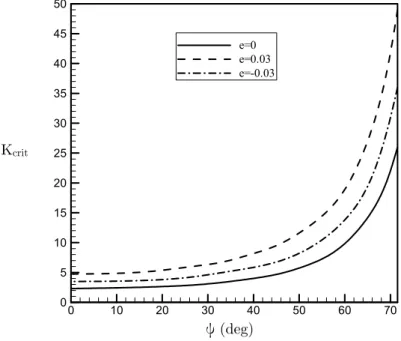
In a similar manner of Figure 7, the variation of the critical force versus inclination angle for three different values of r and for e=0.03 is depicted in Figure 8. It is observed that for all values of r, by increasing the inclination angle, the critical force increases and the manner of increase is the same for all values of r.
Figure 8: Variation of critical load versus inclination angle for e=0.03 and 0.05.
0 10 20 30 40 50 60 70
0 5 10 15 20 25 30 35 40 45 50
e=0 e=0.03 e=-0.03
0 10 20 30 40 50 60 70
0 10 20 30 40 50 60 70
r=2 r=1 r=1.5
ψ (deg) Kcrit
Kcrit
To examine the effect of rotating speed on the critical force of the system, the beam is consid-ered to rotate about its third axis(B3) and simultaneously subjected to a tip follower force. Figure 9 shows the variation of the critical force against the rotating speed of the beam for various values of r and for e=0.03 and 0.05. As the rotating speed increases for r=1, the critical load of the beam decreases monotonically until reaching to zero, but the behavior of the system for other two values of r is a little different. One finds that for r=1.5 and r=2, by increasing the rotating speed, the critical load decreases, but the rate of reduction is variable. For example for r=2, first, the criti-cal load reduces slowly until 3, and from this point until 8, the critical force decreases rap-idly and after that again it decreases slowly.
Figure 9: Variation of critical load versus nondimensional rotating speed for e=0.03 and 0.05.
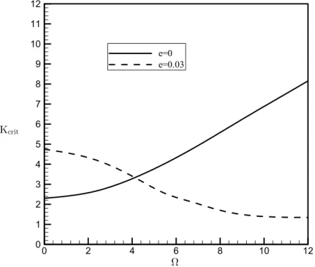
The variation of the critical load by increasing the angular speed of the beam for two different values of e and for r=1.5 is calculated and plotted in Figure 10. It is concluded that the manner of variation of critical load versus rotating speed is surprisingly different for e=0 and e=0.03. In the other words, for e=0, by increasing the angular speed, the critical load increases while for e=0.03 this trend is inverse. It is noted that the results for e<0 is not presented here because for larger values of rotating speed, the imaginary parts of the eigenvalues do not coalescence to each other and they simply veer each other as shown in Figure 11 for e=-0.03 and Ω=30.
The effect of inclination angle on instability boundary of rotating beams for various values of rotating speed is demonstrated in Figure 12 for e=0, r=1.5 and 0.05. It is found that for all values of rotating speed, by increasing the inclination angle, the critical load increases and this trend is almost the same for all values of rotating speed.
0 5 10
0 1 2 3 4 5 6 7
r=1 r=1.5 r=2
Ω
Figure 10: Variation of critical load versus nondimensional rotating speed for r=1.5and 0.05.
Figure 11: Veering of the imaginary parts of the eigenvalues for e=-0.03, Ω=30 and 0.05.
0 2 4 6 8 10 12
0 1 2 3 4 5 6 7 8 9 10 11 12
e=0 e=0.03
0 5 10 15
3 4 5 6 7 8 9
Ω
Kcrit
Figure 12: Variation of critical load versus inclination angle for r=1.5, e=0 and 0.05.
5 CONCLUSION
In this paper, the instability of a rotating and non-rotating beam under an inclined tip follower force has been considered. The beam is modeled by using the geometrically exact fully intrinsic beam equations. The generalized differential quadrature method is used to convert the partial dif-ferential equations to ordinary ones. The stability of the system is determined by investigation the eigenvalues of the linearized system about its equilibrium state. It was found that the proposed method of solution simulates the system accurately. Moreover, the variation of the critical load versus different parameters has been examined, and based on the numerical results, the critical load of the system can be influenced by changing the values of the follower force inclination and magni-tude, rotating speed, distance between the beam center of gravity and elastic center, and cross-sectional properties. Finally, it can be highlighted that the geometrically exact fully intrinsic beam equations are very useful for dynamic instability of rotating and non-rotating beams subjected to tip follower forces.
References
Amoozgar, M.R., Irani, S., Vio, G.A. (2013). Aeroelastic instability of a composite wing with a powered-engine. Journal of Fluids and Structures 36: 70-82.
Amoozgar, M.R., Shahverdi, H. (2016). Analysis of nonlinear fully intrinsic equations of geometrically exact beams using generalized differential quadrature method. Acta Mechanica: 1-13.
Anderson, G.L. (1975). Stability of a rotating cantilever subjected to dissipative, aerodynamic, and transverse follow-er forces. Journal of Sound and Vibration 39: 55-76.
0 10 20 30 40 50 60 70
0 10 20 30 40 50 60 70 80 90
Kcrit
Beck, M. (1952). Die Knicklast des einseitig eingespannten, tangential gedrückten Stabes [The buckling load of the cantilevered, tangentially compressed rod]. Zeitschrift für angewandte Mathematik und Physik ZAMP 3: 225-228. Bellman, R., Casti, J. (1971). Differential quadrature and long-term integration. Journal of Mathematical Analysis and Applications 34: 235-238.
Bert, C.W., Malik, M. (1996). Differential Quadrature Method in Computational Mechanics, A Review. Applied Mechanics Reviews 49: 1-28.
Bolotin, V.V. (1963). Nonconservative Problems of the Theory of Elastic Stability, Pergamon Press. Bolotin, V.V. (1964). The dynamic stability of elastic systems, Holden-Day.
Como, M. (1966). Lateral buckling of a cantilever subjected to a transverse follower force. International Journal of Solids and Structures 2: 515-523.
Detinko, F.M. (2002). Some phenomena for lateral flutter of beams under follower load. International Journal of Solids and Structures 39: 341-350.
Du, H., Liew, K.M., Lim, M.K. (1996). Generalized Differential Quadrature Method for Buckling Analysis. Journal of Engineering Mechanics 122: 95-100.
Du, H., Lim, M.K., Lin, R.M. (1994). Application of generalized differential quadrature method to structural prob-lems. International Journal for Numerical Methods in Engineering 37: 1881-1896.
Du, H., Lim, M.K., Lin, R.M. (1995). Application of generalized differential quadrature to vibration analysis. Journal of Sound and Vibration 181: 279-293.
Fazelzadeh, S.A., Kazemi-Lari, M.A. (2014). Stability Analysis of a Deep Cantilever Beam with Laterally Distribut-ed Follower Force. Journal of Engineering Mechanics 140: 04014074.
Fazelzadeh, S.A., Mazidi, A., Kalantari, H. (2009). Bending-torsional flutter of wings with an attached mass subject-ed to a follower force. Journal of Sound and Vibration 323: 148-162.
Feldt, W.T., Herrmann, G. (1974). Bending-torsional flutter of a cantilevered wing containing a tip mass and sub-jected to a transverse follower force. Journal of the Franklin Institute 297: 467-478.
Green, A.E., Laws, N. (1966). A General Theory of Rods. Mechanics of Generalized Continua: 49-56.
Hegemier, G.A., Nair, S. (1977). A nonlinear dynamical theory for heterogeneous, anisotropic, elasticrods. AIAA Journal 15: 8-15.
Hodges, D.H. (2001). Lateral-torsional flutter of a deep cantilever loaded by a lateral follower force at the tip. Jour-nal of Sound and Vibration 247: 175-183.
Hodges, D.H. (2003). Geometrically Exact, Intrinsic Theory for Dynamics of Curved and Twisted Anisotropic Beams. AIAA Journal 41: 1131-1137.
Hodges, D.H., Patil, M.J. (2002). Effect of thrust on bending-torsional flutter of wings. Journal of Aircraft 39: 371-376.
Kazemi-Lari, M.A., Fazelzadeh, S.A. (2015). Flexural-torsional flutter analysis of a deep cantilever beam subjected to a partially distributed lateral force. Acta Mechanica 226: 1379-1393.
Khaneh Masjedi, P., Ovesy, H. (2014). Large deflection analysis of geometrically exact spatial beams under conserva-tive and nonconservaconserva-tive loads using intrinsic equations. Acta Mechanica 226: 1-18.
Khaneh Masjedi, P., Ovesy, H.R. (2015). Chebyshev collocation method for static intrinsic equations of geometrically exact beams. International Journal of Solids and Structures 54: 183-191.
Lal, R., Saini, R. (2015). On the use of GDQ for vibration characteristic of non-homogeneous orthotropic rectangular plates of bilinearly varying thickness. Acta Mechanica 226: 1605-1620.
Laura, P.A.A., Gutierrez, R.H. (1994). Analysis of Vibrating Rectangular Plates With Non-Uniform Boundary Con-ditions By Using the Differential Quadrature Method. Journal of Sound and Vibration 173: 702-706.
Leipholz, H. (1962). Die Knicklast des einseitig eingespannten Stabes mit gleichmässig verteilter, tangentialer Längs-belastung [The buckling load of the cantilvered rod with uniformly distributed, tangential longitudinal stress]. Zeitschrift für angewandte Mathematik und Physik ZAMP 13: 581-589.
Leipholz, H.H.E. (1978). On variational principles for non-conservative mechanical systems with follower forces. (In Variational Methods in the Mechanics of Solids), Pregamon Press.
Lin, R.M., Lim, M.K., Du, H. (1994). Deflection of plates with nonlinear boundary supports using generalized differ-ential quadrature. Computers & Structures 53: 993-999.
Lin, R.M., Lim, M.K., Du, H. (1994). Large deflection analysis of plates under thermal loading. Computer Methods in Applied Mechanics and Engineering 117: 381-390.
Mardanpour, P., Hodges, D.H., Neuhart, R., Graybeal, N. (2013). Engine Placement Effect on Nonlinear Trim and Stability of Flying Wing Aircraft. Journal of Aircraft 50: 1716-1725.
Mardanpour, P., Richards, P.W., Nabipour, O., Hodges, D.H. (2014). Effect of multiple engine placement on aeroe-lastic trim and stability of flying wing aircraft. Journal of Fluids and Structures 44: 67-86.
Marzani, A., Tornabene, F., Viola, E. (2008). Nonconservative stability problems via generalized differential quadra-ture method. Journal of Sound and Vibration 315: 176-196.
Nair, R.G., Rao, G.V., Singh, G. (2002). Stability of short uniform column subjected to an intermediate force. Jour-nal of Sound and Vibration 253: 1125-1130.
Patil, M.J., Althoff, M. (2011). Energy-consistent, Galerkin approach for the nonlinear dynamics of beams using intrinsic equations. Journal of Vibration and Control 17: 1748-1758.
Patil, M.J., Hodges, D.H. (2006). Flight Dynamics of Highly Flexible Flying Wings. Journal of Aircraft 43: 1790-1799.
Patil, M.J., Hodges, D.H. (2011). Variable-order finite elements for nonlinear, fully intrinsic beam equations. Journal of Mechanics of Materials and Structures 6: 479-493.
Reissner, E. (1973). On one-dimensional large-displacement finite-strain beam theory. Studies in Applied Mathemat-ics 52: 87-95.
Shu, C. (2000). Differential Quadrature and Its Application in Engineering. Springer.
Shu, C., Chew, Y.T., Khoo, B.C., Yeo, K.S. (1996). Solutions of three‐dimensional boundary layer equations by global methods of generalized differential‐integral quadrature. International Journal of Numerical Methods for Heat & Fluid Flow 6: 61-75.
Shu, C., Chew, Y.T., Richards, B.E. (1995). Generalized differential and integral quadrature and their application to solve boundary layer equations. International Journal for Numerical Methods in Fluids 21: 723-733.
Shu, C., Richard, B.E. (1992). Parallel simulation of incompressible viscous flows by generalized differential quadra-ture. Computing Systems in Engineering 3: 271-281.
Shu, C., Richards, B.E. (1992). Application of generalized differential quadrature to solve two-dimensional incom-pressible Navier-Stokes equations. International Journal for Numerical Methods in Fluids 15: 791-798.
Simitses, G.J., Hodges, D.H. (2006). Fundamentals of Structural Stability. Butterworth-Heinemann.
Sotoudeh, Z., Hodges, D.H., Chang, C.S. (2010). Validation Studies for Aeroelastic Trim and Stability of Highly Flexible Aircraft. Journal of Aircraft 47: 1240-1247.
Wohlhart, K. (1971). Dynamische Kippstabilitat eines Platenstreifens unter Folgelast. Zeitschrift fuer Flugwissen-schaften 19: 291-298.