Abstract
With the opening of the Northern Sea for international shipping routes, various vessels prefer to use this option to reach Europe as distance is significantly reduced if a ship is sailing through this route. In the same time, the demand to ensure ship safety rises as impact phenomenon between ship structures and ice causes numer-ous casualties. This work presented a numerical study with a con-centration on contact between ship structures and levels. The dou-ble side skin of a chemical tanker was modelled with a shell ele-ment while a deformable characteristic was impleele-mented on the ice as an indenter. Several target areas on the side structure were set as impact points based on its stiffener component. Different models of indenter were taken into account in order to observe structural responses and influences of external parameters, namely ice topolo-gy, while the described location parameters were taken as the ship’s internal parameters. Impact force was presented with total energy, as well as the ratio between kinetic and internal energy. The de-formation pattern was used as a verification of the collision process and its subsequent results. Finally, the behavior of the inner walls subjected to type indenters was observed as this component is the final component that maintains liquid cargo and resists an impact load.
Keywords
Damage characteristics, side structures, level ice, numerical simula-tion, mechanical properties of ice and steel.
Numerical Simulation for the Collision Between Side Structure
and Level Ice in Event of Side Impact Scenario
1 INTRODUCTION
Due to global warming, the thickness and coverage area of the Arctic Sea ice gradually decreases, which makes Arctic marine transportation and exploitation for oil, gas and other resources possible.
Dong Myung Bae a Aditya Rio Prabowo b,c Bo Cao d
Jung Min Sohn a Ahmad Fauzan Zakki c Qing Wang e
a Department of NavalArchitecture and
Marine Systems Engineering, Pukyong National University, South Korea
b Interdisciplinary Program of Marine
Convergence Design, Pukyong National University, South Korea
c Department of Naval Architecture,
Diponegoro University, Indonesia
d China Shipbuilding Industry
Corpora-tion Economic Research Center, China e College of Shipbuilding Engineering,
Harbin Engineering University, China
http://dx.doi.org/10.1590/1679-78252975
The Arctic route can greatly shorten the voyage from Asia to Europe and reduce the transport cost and time on the sea (Wang and Fan, 2011). Meanwhile, the passing ships have to endure more rig-orous environments and as a result, more accidents occur such as hull-ice collision accidents or low temperature damages. Therefore, the development of a new sea route needs to be further explored in order to ensure the safety of hull structures.
The issue of collision impact between structure and ice is seen as a serious matter since danger-ous goods and even human life are at stake if an accident occurs. Compared to other parts of the ship such as the stern and stem, the side hull construction in the middle region, may be regarded as the most vital component in the collision phenomenon since structural integrity, water environment, and passenger’s safety are dependent on this components condition prior and after fracture. Con-cerns regarding the safety of the middle region has been noted in previous research, such as in the research of Haris and Amdahl (2013). Despite its role, other regions on the ship hull have also been studied when the hull is given different loads depend on impact area during contact, such fore end region’s collision with upper deck of striking ship (Bae et al., 2016; Prabowo et al., 2016). In rela-tion to impact, researchers focus on evaluating structural behaviors and defining critical scenarios. Each scenario can vary according to location, indenter’s topology, velocity, involved objects, etc. which makes possible scenarios limitless. This situation is also part of the attractiveness of this field which is why it is widely studied.
Normally in the collision analyses, most of the research uses the striking body, such as the bulb-ous bow or rocks, as the rigid body to conduct the analysis. However, in the case of an interaction between ice and a structure, the mechanical property of level ice is different from the rigid body, which has high plasticity and can break easily (Suh et al., 2008). In terms of ice characteristics, a series of actual experiments has been conducted by Jones et al. (2003) and Gagnon (Gagnon, 2004a; Gagnon, 2004b; Gagnon and Derradji-Aouat, 2006) in order to define the behavior and mechanical properties of ice when it is in contact with steel. However, the mechanical characteristics of steel materials for the stuck ship in a ship collision changes in a low temperature (Min et al., 2011). Thus, both of the described aspects should be considered in the collision study to achieve more ac-curate results.
In this paper, several collision analyses had been performed using numerical simulations of hull-ice collisions. It considered the material properties for both the level of the hull-ice and steel in a low temperature and it did a comparison to show the different outcomes using different material proper-ties. A proposed ship model was presented based on a chemical vessel that may become a source of environmental disaster. Finally, it summarized the damaged characteristics of a side hull structure in several collision scenarios and presented a reference to improve the crashworthiness.
2 BASIC THEORY AND MATERIAL PROPERTY
2.1 Collision Theory Based on Ice
to a ship striking an ice edge, or ice striking an offshore structure. The energy approach is based on equating the available kinetic energy with the energy expended in crushing as well as the potential energy as presented in Equations 1 to 3.
PE
IE
KE
e
(1)c n
d
F
IE
m
.
0
(2) e nd
F
PE
e
.
0
(3)where KEe denotes the available kinetic energy, IE denotes the energy expended in crushing, PE is
the potential energy, m is mass displacement, c is crushing indentation displacement, and e is
re-coverable displacement.
These equations are the basis of the theory. Equation (1) can be solved for the indentation force
Fn provided that the required kinematic and geometric values are known.
2.2 Material Property for Steel
Generally, the mechanical properties of material, i.e. modulus elasticity, yield strength, and tensile strength, are obtained from testing, such as in the tensile test. When the structure undergoes a plastic deformation, such as in an ultimate strength problem where the plastic strain is not greater, it can be regarded as a large deformation problem but not a large strain problem. In this case, the effects of the material properties in the plastic zone due to inaccuracies is relatively small. However, in the problem of a ship collision in which a member failure and large strain have occurred, the analysis results for the structural behavior can be affected significantly by the plastic material property. Therefore, it is very important to obtain the basic mechanical property for steel, especially in a low temperature. According to the tensile test in one axial, the equation of nominal strain can be received as follows:
0 0 0
L
L
L
L
L
(4)where ΔL denotes the elongation value of specimen in the tensile test, L0 denotes the original length
of specimen in the tensile test, and L is the final length of specimen in the tensile test.
Holloman (1945) presented the relation between stress (σ) and strain ( ) by strain hardening exponent (n) and strength coefficient (K) in the stage of plastic deformation as shown in Equation (5).
n
K
(5)
N i N i i i N i N i N i i i i ix
x
N
y
x
y
x
N
n
1 2 1 21 1 1
(6)
N
x
n
y
K
N i N i i i 1 1exp
(7)where x is log σ, y is log , and N is the number of data.
No. Material type Yield s. (MPa)
Tensile s.
(MPa) n
K (MPa)
T ( ̊C)
1 GL-DH32 375.65 524.11 0.210 891.54 Room T.
2 GL-DH32 451.81 625.16 0.213 1084.41 -30
3 GL-DH32 425.79 571.87 0.220 988.65 -50
4 GL-DH36 385.05 552.06 0.200 929.54 Room T.
5 GL-DH36 425.27 599.13 0.210 1021.28 -30
6 GL-DH36 448.01 596.26 0.230 1048.78 -50
7 GL-EH36 395.24 516.90 0.16 830.11 Room T.
8 GL-EH36 442.57 563.87 0.16 884.50 -30
9 GL-EH36 442.49 572.58 0.18 929.98 -50
Table 1: Mechanical properties of steels in different temperature (Min et al., 2011).
Previous work of Min et al. (2011) observed the mechanical properties of steel in polar condi-tions. Material type GL-DH32, GL-DH36, and GL-EH36 were taken into consideration. These ma-terials can be used as a defined material for the outer shells of vessels that are sailing through low-temperature regions. They have been respectively tested at room low-temperature, -30 ̊C and -50 ̊C by the standard specimen of ASTM (2008). In comparison with the results at room temperature, the yield stress increases by approximately 10% to 13% at -30 ̊C and by 13% to 19% at -50 ̊C, meanwhile the tensile strength increases by about 9% at -30 ̊C and 11% to 14% at -50 ̊C. The mean results of the material properties are shown in detail in Table 1.
2.3 Material Property for Level Ice
Also, this model is implemented in an ice-compressive simulation which is the main idea of the pre-sent work.
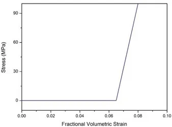
The details of the ice model are explained in Gagnon's crushable foam ice model which was ini-tially developed to reproduce the spatial pressure-area curve with a high central peak load (Gagnon and Derradji-Aouat, 2006). That model is based on the crushable foam material model where the deformation is mostly unrecoverable. A material model is used for crushable foams in side impacts and other applications where cyclic behavior is unimportant. The foam model is strain rate depend-ent and crushes one-dimensionally with a Poisson’s ratio that is essdepend-entially zero. The small Poisson’s ratio limits the material’s deformation in directions other than the loading direction. The main pa-rameters of the ice model are presented in Table 2. The characteristic of stress and strain is applied based on Gagnon’s model which is given in Figure 2.
Density Young’s modulus Poisson’s ratio Tensile stress cutoff Fractional volumetric strain
900 kg/m3 9 GPa 0.003 8 MPa 0.065
Table 2: Material properties of ice for collision simulation.
Figure 1: Characteristic of stress-strain based on Gagnon’s collision experiment.
3 PREPARATION AND METHODOLOGY
3.1 Collision Interaction Scenario
(a) (b)
Figure 2: Illustration of collision phenomenon: (a) structure-ice in a narrow chancel, and (b) impact location.
In other words, ice loads are localized, when being applied to the hull structure, and can be ide-alized as the ice vertically impacts the hull. In order to know the normal damaged characteristics of a side hull structure, a level ice model was used and it collided with a side structure in the setting condition.
3.2 Engineering Model and Configuration
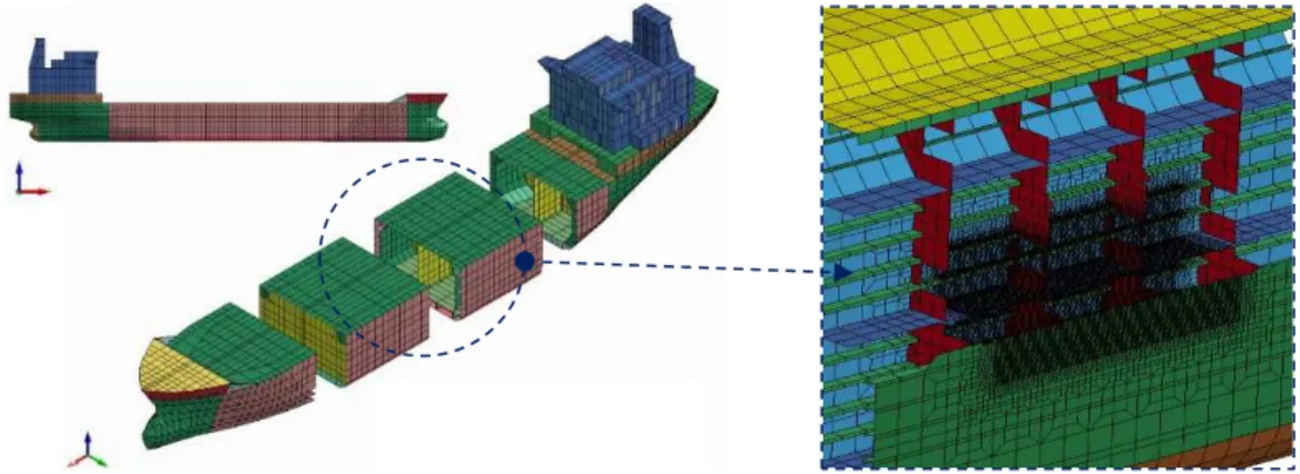
A target ship was built based on a Korean Register 17 000 DWT chemical tanker and its hull structure was designed using double side skin construction. The principal dimensions of the target ship are presented in Table 3. In order to achieve good results with a reasonable time process, the implementation of fine mesh is vital. After fine meshing the designated target structure (Figure 3), a total characteristic number of a numerical model was used consisting of 61 560 nodes and 63 594 elements. The mesh size should be selected so that the modelled section can finely represent the nonlinear behavior of the ship structure.
Item Symbol Value
Length (m) LOA 144.00
Length (m) LPP 136.00
Depth (m) D 12.50
Draft (m) TS 9.20
Breadth (m) B 22.60
Service speed (knot) VS 14.00
Block coefficient CB 0.795
Table 3: Principal dimension of chemical tanker.
The side shell, web frame, and inner skin can be defined into an element that is the same as the web of the side longitudinal, in which the shell element is taken as the main consideration. The area of outer structure which is unexpected contact with ice in event of collision is implemented by coarse mesh since deformation is unlikely found in this area.
Figure 3: Numerical model of the struck ship. Circled middle section denotes target location in collision.
Based on real investigation and other simulation for collision accidents, the damaged defor-mation mainly occurred around the collided zone. Therefore, the boundary condition of the struck body (side structure) was set to be fixed, especially in both ends of the model as shown in Table 4. The striking body had been set for level ice in the first stage, so that the damage could be observed more intuitively. According to the requirements of the International Association of Classification Societies (IACS) and scenario configuration, the speed of the ship in a polar passage is in the range of 1 to 3 m/s depending on the ice-breaking speed and environmental conditions. Therefore, for the present dynamic simulation, it was set that the side structure impacted level ice with a speed of approximately 1.5 m/s in this paper, which was assumed to be equivalent to the same speed when going through an ice channel.
Location Translation Rotation
Dx Dy Dz Rx Ry Rz
Main deck Fix Fix - - Fix Fix
Tank top Fix Fix - - Fix Fix
Edges (the end of model) Fix Fix Fix Fix Fix Fix
Table 4: Boundary condition of the target’s side structures.
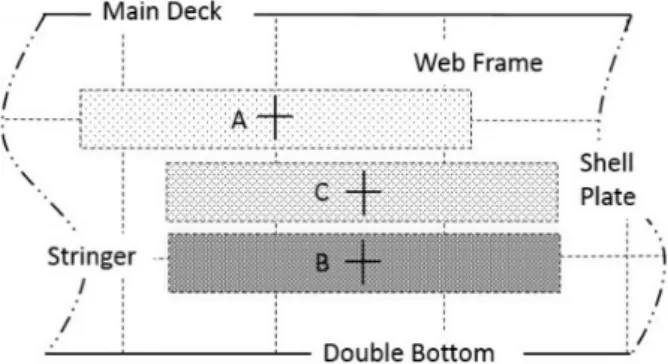
Figure 4: Defined contact regions and structural component on target structure.
There are 3 impacting regions applied to the hull structure respectively and the crosses show the first contact point in a collision with level ice:
1.Region A: the collision simulation is done in the shadow area - A to evaluate the deformation and failure of the hardest part in the side structure;
2.Region B: the collision simulation is done in the shadow area - B to evaluate the deformation and failure of the relatively harder part in the side structure;
3.Region C: the collision simulation is done in the shadow area - C to evaluate the deformation and failure of the weakest part in the side structure.
According to the ice collision scenario and the properties of level ice’s thickness, it is usually less than 1.0 m. The 3 kinds of typical colliding objects are summarized in Figure 5. The following mod-els represent different geometries of level ice and structural modmod-els of the side hull construction respectively.
Figure 5: Involved objects in structure-ice interaction. A section of double skin chemical tanker is presented as location of impacting area, and three ice geometries are proposed as compressive indenter.
Triangular
Comprehensive
4 CALCULATION AND ANALYSIS
The results would show different damage around a specific area, which includes the impacting influ-ence on the different structures. After conducting the dynamic analyses, several structural responses of the collision scenario were collected as follows. The limit state of the analysis is that the inner shell plate ruptures would result in some serious consequences.
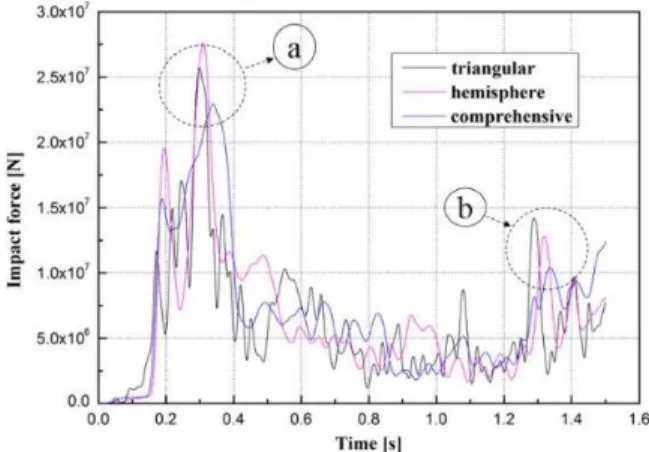
Figure 6: Comparison of impact force at interaction area A. Illustration of crushing process is given in Figure 7.
Figure 6 showed the fluctuation of impact force from different level ice models during an inter-action with area A. There were several kinds of damage forms in the collision process such as bend-ing, membrane tensile and tearing. Initially, depending on the material property, the structure could resist the spontaneous load from an interaction between structure and ice which formed the first high peak regarded as a (Figure 7a). Nevertheless, after passing the peak point, the resistance capa-bility was observed to reduce quickly on account of the main structure breaking. Following this phenomenon, several small fluctuations were recorded during the collision process until the final peak point which was regarded as b in Figure 7b. The structures had resisted the external impact, which meant that it was assumed that the structural component would get torn if the force passed through the final fluctuation after the second peak point. Meanwhile, both of the peak points repre-sented the tensile or contraction of a structural component during the collision process.
ob-tained in the range between 0.5 to 0.7 s during the collision process which meant ice could penetrate respected structural components and thus, the ratio went down as the ice began to crumble.
(a) (b)
Figure 7: Indentation process by hemisphere ice at the pointed time period as addressed in Figure 6: (a) time a, and (b) time b.
Figure 8: Average total energy of side structures in 3 cases of ice models.
Normally, the breaking time of an inner shell plate is important data for researching ship colli-sions, which can determine whether the whole ship is safe and whether there is pollutant leakage or not. According to the limit time, when the inner shell plate ruptures or exceeds the maximum per-missible deformation (Table 5), it shows that the difference is small. Therefore, it leads to the con-clusion that the strength of the double side skin has dependable strength which is successfully and widely distributed on the impacting area. A remarkable distinction was not found which also indi-cates that there are no weak spot on the proposed target point. This result also highlights a good relationship between structural characteristics. Area A which is mainly strengthened by an inter-costal web frame and longitudinal stiffener is considered to be the strongest structure which also needs a longer time process to destroy this target. Other results also produce satisfaction as Area B which consists of a plate and longitudinal stiffener is indicated to be stronger than Area C which is not strengthened by transverse nor longitudinal components.
Impact area Breaking time (s)
Area A 1.472
Area B 1.466
Area C 1.451
Table 5: Breaking time of inner shell plate.
Density Young’s modulus Poisson’s ratio
900 kg/m3 9 GPa 0.003
Table 6: Mechanical properties of rigid ice for collision simulation.
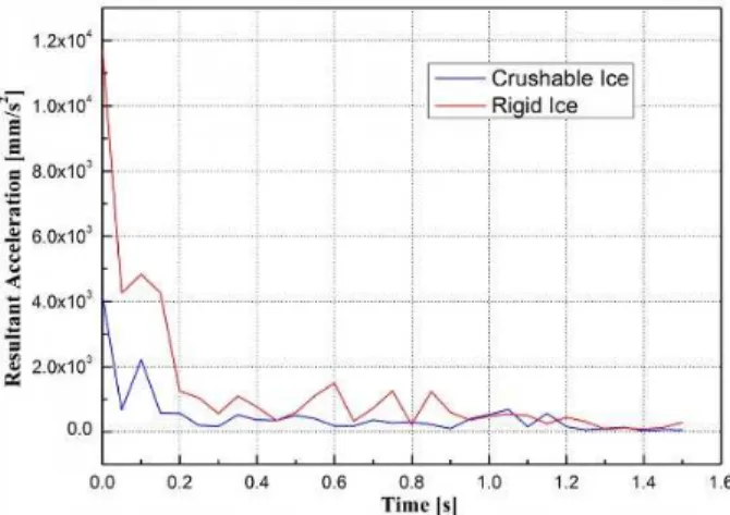
Finally, in order to study the influence of the ice characteristic in the numerical simulation analysis, an additional analysis was conducted in which a rigid characteristic (Table 6) was imple-mented in the ice model. The same mechanical properties were used in rigid ice during an additional simulation where a comprehensive ice model was chosen as an indenter. The condition of the inner shell during a collision with crushable and rigid ice is reported in Figures 10 to 11.
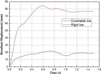
Figure 11: Displacement of inner shell plate during penetrated by crushable and rigid ices.
It can be found from the results of Figures 10 and 11 that the rigid ice model delivered more remarkable damage than the crushable one, especially for the level of displacement. As rigid charac-teristics were applied in the ice model, the indenter could maintain its shape in constant condition which meant it was able to continuously deform its double side skin during the collision process. Different conditions were presented by the crushable ice model which slowly degenerated as it crumbled down. The implementation of the crushable ice model can be considered good enough to produce realistic results, especially in considering the crushing process of ice itself which is an inter-esting part of polar and low temperature fields. However, if the worstcase is taken as a main obser-vation, especially in assessing local and global resistance of ship structures and observing the highest limit and capability of structures subjected to impact or accidental loads, rigid characteristics will provide reasonable results that can estimate structural resistance even in the most extreme condi-tions, e.g. during impact with a larger object. Accompanied by the polar research, the combination of rigid and crushable analyses will deeply develop and improve simulation accuracy as well as fur-ther development on the design of double side side skin structure, such as the selection on steel strength level, and reduction of the total weight.
5 CONCLUSIONS
Finally, this paper presented the damaged characteristics of side hull structures in a hull-ice col-lision. From the results of numerical simulation analysis, there were several kinds of confirmed damage forms in the collision process , such as bending, membrane tensile and tearing. Especially for the shell plate, a lot of deformation always appeared whenever a collision occurred. Nevertheless, as with the preceding viewpoints, the shell plate was considered to deliver a major contribution in its ability to resist the colliding force on a large scale. Results on energy response during a collision process also indicated that other strong structures - web frames and stringers - provided good re-sistance so the inner hull was unable to be penetrated by an indenter. Based on the present work, in order to improve the crashworthiness, attention on how to prevent the main structure tearing or make it happen as late as possible based on the damage characteristics of side structure, it is rec-ommended that this aspect be added as a parameter in assessing structural capability, especially accounting for impact load. Comparative studies between crushable and rigid characteristics is seri-ously encouraged to be performed widely in structural analysis in which the crushing mode of ice model is taken as the main observation.
Acknowledgement
This study was successfully presented and published with the support from BK21 plus MADEC Human Research De-velopment Group, Republic of Korea. The gratitude was addressed to Laboratory of Ship Structure and Vibration Analysis, PKNU that provided a full-support for the authors during experiment, observation, and manuscript writing.
References
ASTM, (2008). ASTM E646-07: Standard test method for tensile strain-hardening exponents (n-values) of metallic steel materials. American Society for Testing Material.
Bae, D.M., Cao, B., (2014). A study on strength analysis of normal merchant ship collided with level ice. Proceedings of 2nd International Symposium on Naval Architecture and Maritime, Yildiz Technical University, Istanbul, Turkey. Bae, D.M., Prabowo, A.R., Cao, B., Zakki, A.F., Haryadi, G.D., (2016). Study on collision between two ships using selected parameters in collision simulation. Journal of Marine Science and Application 15: 63-72.
Daley, C.G., (1999). Energy based ice collision forces. Proceedings of the 15th International Conference on Port and Ocean Engineering under Arctic Conditions, Espoo, Helsinki University of Technology, Finland.
Gagnon, R., (2004a). Analysis of laboratory growler impact test. Cold Regions Science and Technology 39: 1-17. Gagnon, R., (2004b). Side-viewing high-speed video observations of ice crushing. Proceedings of the 17th International International Symposium on Ice, Saint Petersburg, Russia.
Gagnon, R., Derradji-Aouat, A., (2006). First results of numerical simulations of bergy bit collisions with the CCGS terry fox icebreaker. Proceedings of the 18th IAHR International Symposium on Ice, Sapporo, IAHR & AIRH, Japan. Haris, S., Amdahl, J., (2013). Analysis of ship-ship collision damage accounting for bow and side deformation interac-tion. Marine Structures 32: 18-48.
Holloman, J.H., (1945). Tensile deformation, New York, American Institute of Mining, Metallurgical, and Petroleum Engineers.
Jones, S.J., Gagnon, R.R., Derradji, A., Bugden, A. (2003). Compressive strength of iceberg ice. Canadian Journal of Physics 81: 91-100.
Prabowo, A.R., Bae, D.M., Sohn, J.M., Zakki, A.F., (2016). Evaluating the parameter influence in the event of a ship collision based on the finite element method approach. International Journal of Technology 4: 592-602.
Suh, Y.S., Ito, H., Chun, S.G., (2008). Ice collision analyses for membrane tank type LNG carrier. Journal of Ship and Ocean Technology 12 (1): 35-44.