Abstract
This paper presents an experimental investigation on the axial crushing of coiled expanded metal tubes subjected to quasi-static compressive loading. The investigation aims at comparing the ener-gy absorption characteristics between tubes fabricated with coiled expanded metal meshes and solid plates. Then, a series of quasi-static axial crushing tests were performed to obtain the structural performance on coiled tubes, and then compare these with round and square solid tubes. Coiled tubes were fabricated using circular and square geometries, as well as various cell orientations. The results showed that cell orientation enhance the energy absorption response of the coiled tubes. Regarding these responses in compari-son to those of solid tubes, the results showed that for coiled and solid tubes with the same weight, the energy absorption capacity of the former is much lesser than the latter.
Keywords
Energy absorption, axial crushing, expanded metal, collapse modes.
Energy Absorption Characteristics of Coiled
Expanded Metal Tubes Under Axial Compression
1 INTRODUCTION
Over the last decades, there has been an increasing interest among scientist and practitioners to-wards the investigation of thin-walled metallic members capable to absorb a great amount of energy by plastic deformation. Several researchers have challenged themselves looking for the best configu-rations (geometries and materials) to guarantee a stable and progressive collapse diminishing to the maximum the load transmitted to the structure.
Dimas J. Smith a Carlos A. Graciano b Paulo Teixeira c Gabriela Martínez c Alberto Pertuzd
a Universidad Nacional Experimental
Francisco de Miranda, Falcón, Venezuela. [email protected]
b UniversidadNacional de Colombia, Sede
Medellín, Medellín, 050034, Colombia, [email protected]
c Universidad Simón Bolívar, Caracas,
Venezuela. [email protected], [email protected]
d Universidad Industrial de Santander,
Bucaramanga, Colombia, [email protected]
http://dx.doi.org/10.1590/1679-78253242
Significant efforts that reflects the growth of this field have been summarized in state-of-the-art reviews. Firstly, Alghamdi (2001) reviewed a great amount of research on the structural response of typical structural shapes, used as collapsible energy absorbers. Secondly, Olabi et al. (2007) also conducted a state-of-the-art review on metallic tubes used as energy absorbers under various loading cases. A more detailed review was presented by Yuen and Nurick (2008), examining the effect of initial imperfections (geometric or material) on the structural response of tubular members under axial loading. From a material selection point of view, Meidell (2009) provided guidelines for mate-rial selection when designing tubes for axial crushing applications. More recently, Jones (2010) re-viewed the performance of various energy-absorbing systems based on the energy-absorbing effec-tiveness factor. As a final point, these reviews and the literature cited therein revealed that metallic energy absorbers under axial compressive loads fail in various modes depending essentially on: ma-terial properties, geometrical parameters, and initial imperfections.
In order to improve the collapsibility and energy absorption capacity of tubular members, mul-ticorners structural shapes have been used (Fang et al. 2013; Hong et al. 2013). Structural imperfec-tions have also become a mean to achieve a progressive collapse of structural members. Hence, tubes with large openings (Song et al. 2013a; Song and Guo 2013; Song et al. 2013b) and corruga-tions (Eyvazian 2014) have been used to mitigate the peak loads exerted in the structural response of the thin-walled members. Nested tubes placed concentrically are also a feasible alternative to enhance the performance of energy absorbers (Haghi et al. 2013). Nia et al. (2015, 2016a, 2016b) investigated the energy absorption characteristics of nested multi-tubular structures. In several cases the tubes are foam-filled in order to modify the deformation patterns and to smooth the insta-ble responses (Zhang et al. 2010, 2011, 2012; Niknejad and Orojloo 2016). Nested tubes can also be placed transversally, in innovative configurations, for crashworthy applications (Morris et al. 2006, 2007; Baroutaji et al. 2016). The advantage of using these type of tubes is the possibility of nesting an array of tubes of various diameters reducing the occupied space, and the tubes may undergo additional deformation to obtain oblong configurations which allow larger crushing displacements than for circular ones (Baroutaji et al. 2014).
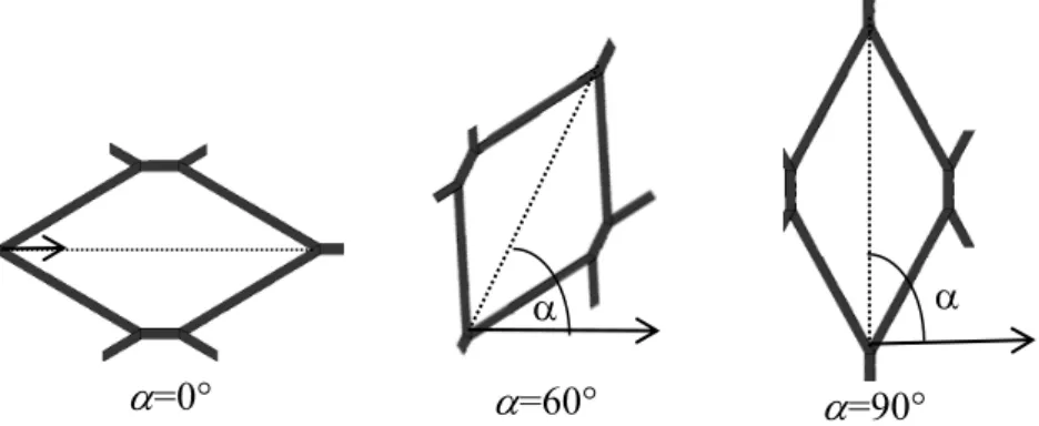
Tubes manufactured with expanded metal meshes appear as a suitable alternative for energy absorption applications (Smith et al. 2009, Graciano et al. 2012). Expanded metal meshes are com-posed of cells that can be oriented in different ways as shown in Figure 1. It has been demonstrated that the axial crushing response of expanded metal tubes depends significantly on the cell orienta-tion. On the one hand, for α =0° the failure mechanism can be stable and the cells collapse progres-sively. In contrast, for α =90° the collapse can be rather instable. Placing expanded metal tubes concentrically enhances the energy absorption characteristics of the individual configurations (Mar-tínez et al. 2013, Smith et al. 2014).
Figure 1: Orientations of the expanded metal cells (Smith et al. 2014).
2 EXPERIMENTAL SETUP
Figure 2 shows a schematic view of an expanded metal cell, the pattern is characterized by two orthogonal axes, a minor one (L2) in the slitting direction and a major one (L1). The expanded
met-al meshes used in the experiments had: strand thickness t=1.05mm, strand width w= 2.50mm, ma-jor axis L1= 65.20mm, and minor axis L2= 27.50mm.
Figure 2: Geometric characteristics of an expanded metal cell.
The experiments were aimed at comparing the performance of coiled expanded metal tubes with that of solid tubes subjected to quasi-static axial compression. The expanded metal sheets were manufactured using an ASTM A-569 steel with yield strength 246MPa, ultimate strength 385MPa, Young’s modulus 205MPa and Poisson ratio 0.3 (Sanchez 2005). For the solid tubes the base mate-rial is an ASTM A-500a, tensile coupons were prepared and tested according to ASTM 8M-01 Standards, giving as results a yield strength of 235MPa, and ultimate strength of 360MPa.
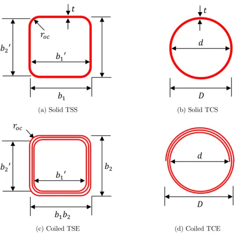
Figure 3 shows the cross section of both, the solid and the coiled expanded metal tubes. Tables 1 to 4 presents the measured dimensions of the test specimens. These specimens are designated ac-cording to their geometries: TCS for circular solid tubes, TSS for square solid tubes, TCE for circu-lar and TSE for square coiled expanded metal tubes. For instance TCE0-01 has a mesh oriented at
=0°, and is the specimen 01 in their series.
=0°
=60°
=90°
(a) Solid TSS (b) Solid TCS
(c) Coiled TSE (d) Coiled TCE
Figure 3: Specimenscross section.
For the square tubes (TSS and TSE) in Tables 1 and 3: L is the length; and b1 and b2 are the
dimensions of the outer sides for the tube, t is the thickness, roc is the corner radius and W is the
weight. For these tubes two additional parameters are included, b1’ and b2’ are the dimensions of
the inner sides for the tube. For the round tubes (TCS and TCE) in Tables 2 and 4: L is the length,
D is the external diameter, d is the internal diameter, t is the thickness and W is the weight.
Specimens L (mm) b1 (mm) b2(mm) t (mm) roc(mm) W (g)
TSS-01 305.12 101.60 101.60 1.49 2.81 1338.5
TSS-02 304.87 101.49 101.46 1.59 2.81 1338.4
TSS-03 305.01 101.39 101.39 1.61 2.82 1336.4
Table 1: Dimensions of TSS tubes.
Specimens L (mm) D (mm) d (mm) t (mm) W (g)
TCS-01 305.00 101.30 99.71 1.59 1044.2
TCS-02 304.56 101.50 99.85 1.55 1051.6
TCS-03 304.78 101.15 99.47 1.48 1045.4
Table 2: Dimensions of TCS tubes.
′
′
Specimens ° L (mm) b1(mm) b2(mm) b1’(mm) b2’(mm) W (g)
TSE0-01 0 312.50 103.00 102.00 49.50 53.00 1341.80
TSE0-02 0 309.50 104.00 100.00 51.50 51.00 1337.50
TSE0-03 0 303.00 98.00 100.00 48.00 52.0 1356.40
TSE60-01 60 308.00 98.00 104.00 52.00 51.00 1329.90
TSE60-02 60 310.00 106.00 108.00 54.00 55.00 1340.30
TSE60-03 60 309.00 102.00 100.00 52.00 51.00 1302.70
TSE90-01 90 309.50 94.00 95.00 50.00 51.00 1344.10
TSE90-02 90 310.00 100.00 101.00 48.00 50.00 1332.50
TSE90-03 90 310.50 99.00 98.00 49.00 48.00 1302.30
Table 3: Dimensions ofTSE tubes.
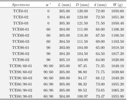
Specimens ° L (mm) D (mm) d (mm) W (g)
TCE0-01 0 305.00 120.00 72.00 1050.60
TCE0-02 0 304.40 123.00 72.50 1051.30
TCE0-03 0 305.30 121.50 71.50 1050.40
TCE60-01 60 304.00 111.00 68.00 1106.30
TCE60-02 60 305.00 110.30 67.50 1100.50
TCE60-03 60 304.50 111.50 69.00 1103.50
TCE90-01 90 303.00 104.00 65.00 1018.50
TCE90-02 90 304.20 104.50 64.50 1017.20
TCE90-03 90 305.10 103.00 64.00 1020.00
TCE90/60-01 90/60 305.00 97.45 71.35 1049.10
TCE90/60-02 90/60 305.00 96.80 71.75 1039.60
TCE90/60-03 90/60 300.00 94.17 68.12 1049.20
TCE60/90-01 60/90 305.00 96.32 73.00 1055.20
TCE60/90-02 60/90 305.00 98.52 73.65 1065.20
TCE60/90-03 60/90 304.00 100.97 73.47 1055.90
Table 4: Dimensions of TCE tubes.
Figures 4 and 5 show the cell orientation of the test specimens, each coiled tube was manufac-tured independently by cutting the expanded metal sheets and then coiling them to form the square and round cross-sections. For each geometry combination, three specimens were fabricated in order to check the repeatability of the results. In the experiments with TCE tubes, two combinations of meshes were added; i.e.=60°/90° and =90°/60°. Finally, a total of 30 tests were performed, 3 for TCS tubes, 3 for TSS tubes, 9 for TSE tubes and 15 for TCE tubes.
α=0⁰ α=60⁰ α=90⁰ Solid
Figure 4: Cell orientation for TSE and TSS tubes.
α=0⁰ α=60⁰ α=90⁰ α=90⁰+60⁰ α=60⁰+90⁰ Solid Figure 5: Cell orientation for TCE and TCS tubes.
To complete the experimental setup, each specimen was axially loaded until failure by using a displacement-controlled hydraulic actuator having a capacity of 200kN and maximum stroke of 300mm. Figure 6 shows the experimental setup employed in the experiments, the specimens were simply supported during the tests. The load was transmitted quasi-statically to the top end and then registered through a loading cell to which a vertical actuator was connected. Load-displacement data were recorded continuously at a time of 0.1 seconds and at a constant cross-head speed of 5 mm/min.
3 EXPERIMENTAL RESULTS AND DISCUSSION
3.1 Load-Displacement Responses and Deformation Patterns
α=90°/60° and TCE 6090 with α=60°/90° (the first angle corresponds to the outside mesh and the second one to the inner one). The progressive collapse of the TSE and TCE specimens are presented in Figures 8 and 10, respectively. Furthermore, Figure 11 shows the average load-displacement curves for the two cross sections.
Correspondingly, for the solid tubes, TSS and TCS, the load-displacement responses and col-lapse modes are shown in Figures 12 and 13.
Figure 6: Experimental setup.
(a) α=0° (b) α=60°
(c) α=90°
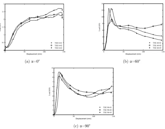
Figure 7: Load-displacement response for TSE tubes.
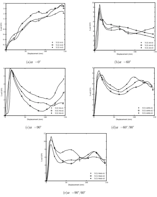
From the load-displacement curves plotted in Figures 7a to 7c and Figures 9a to 9e, the struc-tural behavior of tubes with single and combined cell orientations depends significantly on the cell orientation angle α. This behavior is very similar for both TSE and TCE geometries.
0 50 100 150
0 0.5 1 1.5 2 2.5 3 Displacement (mm) Lo ad (k N ) TSE 0-01 TSE 0-02 TSE 0-03
0 50 100 150
0 2 4 6 8 10 12 14 Displacement (mm) Lo ad (k N ) TSE 60-01 TSE 60-02 TSE 60-03
0 50 100 150
In Figure 7a (TSE0) and 9a (TCE0), for α=0°, the structural response is rather stable, it has a positive slope and the curves show a gradual increase of the load with increasing displacements. This behavior is desirable for energy-absorbing systems, where energy should be dissipated in a controlled way.
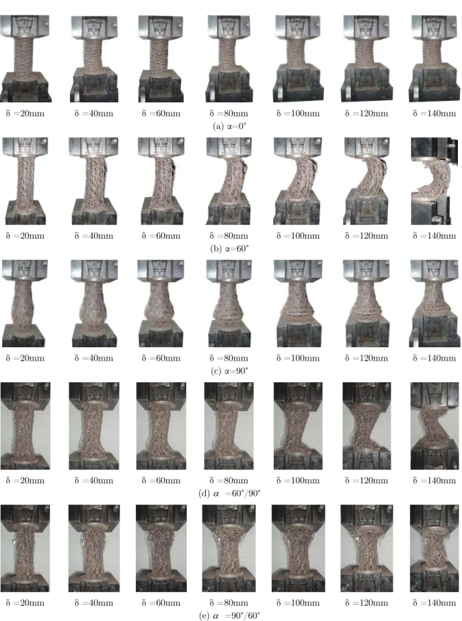
As seen in Figures 8a and 10a, all specimens with α=0° underwent progressive folding in the same direction of the minor axis of the expanded metal and some lateral buckling is achieved for TSE tubes. These collapse modes are consistent with previous work (Graciano et al. 2009, 2012).
Figures 7b and 7c, and corresponding Figures 9b and 9c, show that for other individual angles (TSE60, TSE90, TCE60 and TCE90) the structural responses are more unstable. The load increase rapidly until it reaches the initial peak force, thereafter the curve drops sharply until achieving a steady value. It is important to point out that this behavior is typical for imperfection-sensitive structural members under compression. For expanded metal tubes, initial imperfections are a trigger for unstable behavior and are always present in their geometries. In the post-peak region, all the load-displacement responses exhibit an unstable behavior produced by the contact between the strands after closing the expanded metal cells.
δ =20mm δ =40mm δ =60mm δ =80mm δ =100mm δ =120mm δ =140mm
(a) =0°
δ =20mm δ =40mm δ =60mm δ =80mm δ =100mm δ =120mm δ =140mm
(b) =60°
δ =20mm δ =40mm δ =60mm δ =80mm δ =100mm δ =120mm δ =140mm
(c) =90°
In particular, TSE60 and TCE60 specimens exhibited a rather irregular plastic folding pattern at failure (Figures 8b and 10b). The initial deformation was followed by local collapse of the strands, in which the failure was initiated at the middle of the tube leading to overall column-like buckling.
(a) =0° (b) =60°
(c) =90° (d) =60°/90°
(e) =90°/60°
Figure 9: Load-displacement response for TCE tubes.
0 50 100 150
0 0.2 0.4 0.6 0.8 1 1.2 1.4 1.6 1.8 Displacement (mm) Lo ad (k N ) TCE 0-01 TCE 0-02 TCE 0-03
0 50 100 150
0 1 2 3 4 5 6 7 8 9 10 Displacement (mm) Lo ad (k N ) TCE 60-01 TCE 60-02 TCE 60-03
0 50 100 150
0 1 2 3 4 5 6 Displacement (mm) Lo ad (k N ) TCE 90-01 TCE 90-02 TCE 90-03
0 50 100 150
0 1 2 3 4 5 6 7 8 9 Displacement (mm) Lo ad (k N ) TCE 6090-01 TCE 6090-02 TCE 6090-03
0 50 100 150
δ =20mm δ =40mm δ =60mm δ =80mm δ =100mm δ =120mm δ =140mm (a) α=0°
δ =20mm δ =40mm δ =60mm δ =80mm δ =100mm δ =120mm δ =140mm
(b) α=60°
δ =20mm δ =40mm δ =60mm δ =80mm δ =100mm δ =120mm δ =140mm
(c) α=90°
δ =20mm δ =40mm δ =60mm δ =80mm δ =100mm δ =120mm δ =140mm
(d) =60°/90°
δ =20mm δ =40mm δ =60mm δ =80mm δ =100mm δ =120mm δ =140mm
(e) =90°/60°
On the other hand, a closer look at the load-displacement responses of TSE90 and TCE90 spec-imens revealed a fluctuating behavior in the post peak area as shown in Figures 7c and 9c. Defor-mations with buckling of the individual cells at the lower end of the specimens followed by distor-tion and outward displacements in the cross-secdistor-tion are observed in Figures 8c and 10c. This local collapse mechanism of outward displacements in the cross sections overrides the column buckling of the coiled tube.
In Figures 9d and 9e, instable structural responses are observed for the combined TCE6090 and TCE9060 specimens. An observation of the crushing stages of the tested specimens showed that interaction between the outer and inner meshes at failure may be the reason for the increase in en-ergy absorption capacity (Figures 10d and 10e). The outer mesh restricts the outward displacement of the inner mesh, reducing the possibility of failure and hence enhancing the load energy absorp-tion performance of the coiled tubes. Generally, expanded metal tubes absorb energy by buckling of the strands or formation of plastic hinges at the nodes. The results show that the use of combined coiled tubes with different cell orientation is an effective mean to enhance energy absorption capaci-ty.
This enhancement is caused by the combination of plastic collapse mechanisms originated by a change in the buckling modes, which for some cases leads to a rather unstable structural response. TCE9060 tubes have higher peak responses than TCE6090, but the post-buckling path is similar. Additionally it was observed a notably inward deformation of the cross-section at mid- length of these tubes (Figures 10d and 10e).
(a) TSE (b) TCE
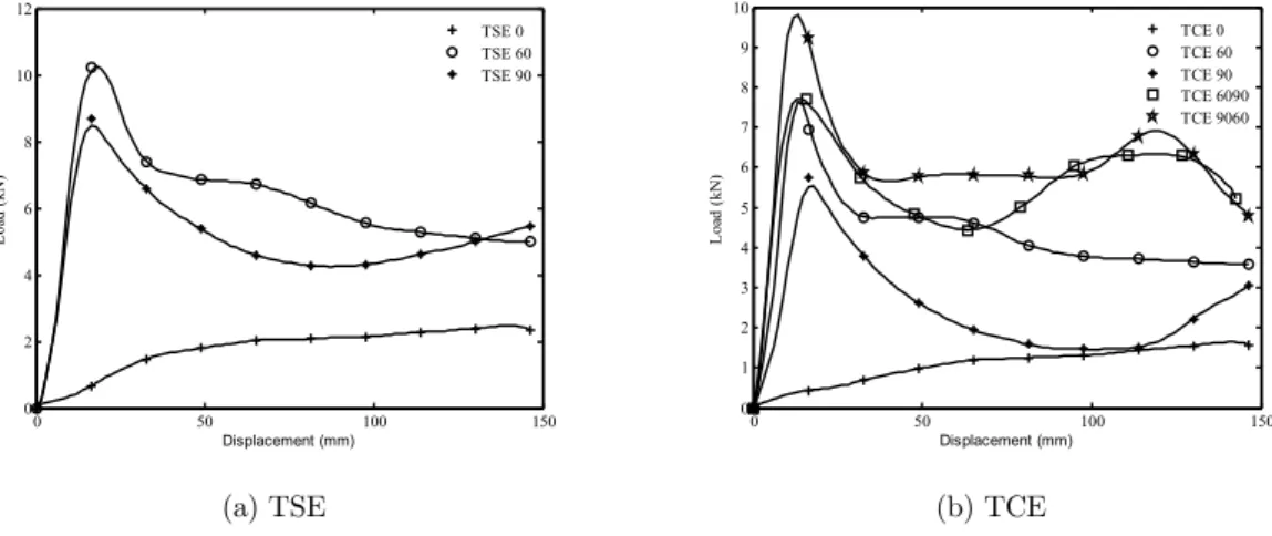
Figure 11: Average load-displacement responses for TSE and TCE tubes.
A comparison of the load-displacement responses for TSE and TCE tubes is shown in Figure 11, respectively. For TSE tubes (Figure 11a) the peaks loads are higher than for TCE tubes (Figure 11b), and within the TCE tubes the best performance is observed for the combined geometries (TCE9060 and TCE6090).
Figures 12a and 12b show typical load-displacement curves for solid TSS and TCS tubes. This fluctuating behavior corresponds to the formation of lobes in the deformed specimens. For TCS tubes, Figures 13a and 13b show that the collapse modes respectively are consistent with those
ob-0 50 100 150
0 2 4 6 8 10 12 Displacement (mm) Lo ad (k N ) TSE 0 TSE 60 TSE 90
0 50 100 150
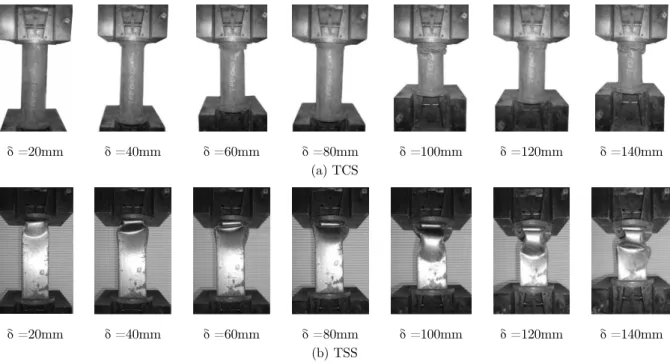
served in previous works (Abramowicz and Jones 1984, Jones and Abramowicz 1985). As shown in Figure 13a, the mode of collapse for round geometries was mixed, i.e. a combination of both axi-symmetric concertina mode and non-axi-symmetric buckling mode with a variable number of circum-ferential lobes.
(a) TCS (b) TSS
Figure 12: Load-displacement responses for solid tubes.
Figure 13b shows the displacement evolution and deformation pattern of TSS tubes. An axis-symmetric mode was observed for these geometries. Consequently, the deformation pattern of TSS tubes showed layers with two opposite lobes which move outwards while the remaining two lobes moved inwards. It is worth mentioning that the deformation modes for TSS tubes were consistent for all the tests.
δ =20mm δ =40mm δ =60mm δ =80mm δ =100mm δ =120mm δ =140mm
(a) TCS
δ =20mm δ =40mm δ =60mm δ =80mm δ =100mm δ =120mm δ =140mm
(b) TSS
Figure 13: Progressive collapse for solid tubes; a) TCS, b) TSS.
0 50 100 150
0 10 20 30 40 50 60 70 80
Displacement (mm)
Lo
ad
(k
N
)
TCS-01 TCS-02 TCS-03
0 50 100 150
0 10 20 30 40 50 60 70 80
Displacement (mm)
Lo
ad
(k
N
)
3.2 Energy Absorption Characteristics
To measure the energy absorption capacity, the following parameters were calculated: initial peak load (Fpeak), mean load (Fm), absorbed energy (Ea), specific energy absorbed (SEA), and the
struc-tural efficiency (). All these parameters were calculated up to a crushing length lc=150mm.
At first place, the absorbed energy is calculated integrating the load-displacement curves as
(1)
where P is the measured force and lc is the crushing length. The mean force Pm based on the area
under the curve over the crushing distance lc is calculated by
(2)
Afterward, the specific energy absorbed (SEA) is calculated by dividing the absorbed energy Ea
by its weight W according to
(3)
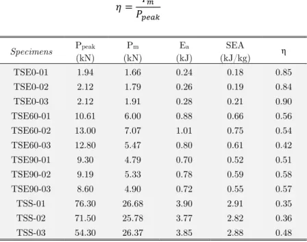
Finally, the structural efficiency defined as the ratio between the mean Pm and the peak force Ppeak is calculated with
(4)
Specimens Ppeak
(kN)
Pm
(kN)
Ea
(kJ)
SEA
(kJ/kg) η
TSE0-01 1.94 1.66 0.24 0.18 0.85
TSE0-02 2.12 1.79 0.26 0.19 0.84
TSE0-03 2.12 1.91 0.28 0.21 0.90
TSE60-01 10.61 6.00 0.88 0.66 0.56
TSE60-02 13.00 7.07 1.01 0.75 0.54
TSE60-03 12.80 5.47 0.80 0.61 0.42
TSE90-01 9.30 4.79 0.70 0.52 0.51
TSE90-02 9.19 5.33 0.78 0.59 0.58
TSE90-03 8.60 4.90 0.72 0.55 0.57
TSS-01 76.30 26.68 3.90 2.91 0.35
TSS-02 71.50 25.78 3.77 2.82 0.36
TSS-03 54.30 26.37 3.85 2.88 0.48
Specimens Ppeak
(kN)
Pm
(kN)
Ea
(kJ)
SEA
(kJ/kg) η
TCE0-01 1.19 1.03 0.15 0.14 0.86
TCE0-02 1.41 1.18 0.17 0.16 0.83
TCE0-03 1.27 1.13 0.15 0.14 0.88
TCE60-01 9.00 4.14 0.61 0.54 0.46
TCE60-02 8.28 4.58 0.67 0.60 0.55
TCE60-03 10.00 4.18 0.61 0.55 0.41
TCE90-01 5.79 3.23 0.47 0.46 0.55
TCE90-02 6.10 1.78 0.26 0.25 0.29
TCE90-03 5.99 2.26 0.33 0.32 0.37
TCE90/60-01 10.51 6.71 0.98 0.93 0.63
TCE90/60-02 11.40 5.95 0.87 0.81 0.52
TCE90/60-03 9.21 5.67 0.83 0.78 0.61
TCE60/90-01 7.71 5.83 0.85 0.81 0.75
TCE60/90-02 8.60 5.23 0.76 0.73 0.60
TCE60/90-03 8.05 5.44 0.80 0.75 0.67
TCS-01 81.00 43.51 6.36 6.09 0.53
TCS-02 79.00 44.54 6.51 6.19 0.56
TCS-03 80.10 39.39 5.76 5.51 0.49
Table 9: Experimental results for TCE and TCS specimens.
Tables 8 and 9 show the energy absorption characteristics for both, the coiled expanded metal tubes TSE and TCE, and for the solid tubes TSS and TCS. Summing up, the main finding of this experimental study are summarized as follows:
Comparing the peak loads, the highest values correspond to the solid tubes, for the square TSS an average Ppeak=67.33kN was attained, and for the circular TCS an average Ppeak=80.03kN was measured. In general, circular geometries are more efficient than square
ones, for TCS specimens the efficiency was higher than for the TSS specimens.
Coiled specimens with α=0°, TSE0 and TCE0, achieved the highest structural efficiency η, their average value is above 0.8. As seen in Figures 6a and 8a their structural responses were the most stable. For the square geometries, the lowest efficiency corresponds to the solid tubes TSS (η =0.35-0.48). On the other hand, for the circular geometries the lowest efficiency corresponds to TCE60 specimens (η =0.41-0.55).
Analyzing the compression strength of the tested specimens, it is observed that the solid tubes (TSS and TCS) outperform the coiled expanded metal tubes (TSE and TCE). Tables 1 to 4 showed that for specimens with similar geometries (square or circular), their corre-sponding weights were similar. Nevertheless, both the energy absorbed Ea and the specific
en-ergy absorbed SEA reported in Tables 8 and 9 are much higher for the solid TSS and TCS tubes. Even though, the amount of material for plastic deformation seems to be similar the cross-sections are quite different due to the lack of continuity in the expanded metal meshes. Additionally, these structural geometrical imperfections improves collapsibility.
for circular tubes the highest average peak load were Ppeak=9.09kN for TCE60 specimens,
and Ppeak=10.37kN for combined TCE6090 specimens.
4 CONCLUSIONS
A study of the energy absorption characteristics of coiled expanded metal tubes subjected to quasi-static compressive load was conducted herein. In the experiments, a parametric study was carried considering the orientation of the expanded metal cells on the structural response of the coiled tubes. The results showed that TSE geometries oriented at α=60° has the highest peak load and the best energy performance. However, TSE geometries with α=0° has better efficiency η, hence the more stable response.
On the other hand, TCE geometries, has a similar response than TSE tubes. α=60° has the high-est peak load and the bhigh-est energy performance. TSE geometries has better performance than TCE tubes comparing SEA efficiency. Combined TCE specimens improves the performance getting better SEA efficiency values than for single configuration. Nevertheless, when comparing the responses of the TSE specimens with those of the solid TSS tubes the peak forces and the specific energy absorbed are at least 4 times smaller, though the structural efficiency is higher for the former than for the latter.
Finally, for energy absorption purposes tubes with α=0° has the desirable stable response, but combined probes seems to improve the performance without decreasing the stability.
References
Abramowicz, W., Jones, N., (1984). Dynamic axial crushing of square tubes. International Journal of Impact Engi-neering 2(2):179-208.
Alghamdi, A,A,A., (2001). Collapsible impact energy absorbers: an overview. Thin-Walled Structures 39:189-213. American Society for Testing Materials. Standard Test Methods for Tension Testing of Metallic Materials. Standard ASTM 8M-01, ASTM International. 2004. West Conshohocken, USA. pp. 57-72.
Baroutaji, A., Gilchrist, M.D., Olabi, A.G., (2016). Quasi-static, impact and energy absorption of internally nested tubes subjected to lateral loading. Thin-Walled Structures 98B:337–350,
Baroutaji, A., Morris, E., Olabi, A.G., (2014). Quasi-static response and multi-objective crashworthiness optimization of oblong tube under lateral loading. Thin-Walled Structures 82:262–77.
Expanded Metal Manufacturers Association (EMMA). Division of the National Association of Architectural Metal Manufacturers (NAAM) “EMMA 557-12: Standards for expanded metal”, 2012.
Eyvazian, A., Habibi, M.K., Hamouda, A.M., Hedayati, R., (2014). Axial crushing behavior and energy absorption efficiency of corrugated tubes. Materials and Design 54:1028–38.
Fan, Z., Lu, G., Liu, K., (2013). Quasi-static axial compression of thin-walled tubes with different cross-sectional shapes. Engineering Structures 55:80–89.
Graciano, C., Martínez, G., Gutiérrez, A., (2012). Failure mechanism of Expanded Metal Tubes under Axial Crush-ing. Thin-Walled Structures 51:20–24.
Graciano, C., Martínez, G., Smith, D., (2009). Experimental investigation on the axial collapse of expanded metal tubes. Thin-Walled Structures 47:953–61.
Haghi, M., Shahsavari, H., Akbarshahi, H., Shakeri, M., (2013). Bitubular square tubes with different arrangements under quasi-static axial compression loading. Materials and Design 51:1095–103.
Jones, N., (2010). Energy-absorbing effectiveness factor. International Journal of Impact Engineering 37:754-65. Jones, N., Abramowicz, W., (1985). Static and dynamic axial crushing of circular and square tubes. Metal Form Impact Mechanics 10:225-47.
Martínez, G., Graciano, C., Teixeira, P., (2013). Energy absorption of axially crushed expanded metal tubes. Thin-Walled Structures 71:134–46.
Meidell, A., (2009). Computer aided material selection for circular tubes designed to resist axial crushing. Thin-Walled Structures 47(8):962-69.
Morris, E., Olabi, A.G., Hashmi, M.S.J., (2006). Analysis of nested tube type energy absorbers with different indent-ers and exterior constraints. Thin-Walled Structures 44:872–85.
Morris, E., Olabi, A.G., Hashmi, M.S.J., (2007). Lateral crushing of circular and non-circular tube systems under quasi-static conditions. Journal of Materials Processing Technology 191:132–35.
Nia, A.A., Chahardoli, S., (2016). Mechanical behavior of nested multi-tubular structures under quasi-static axial load. Thin-Walled Structures 106:376–389.
Nia, A.A., Chahardoli, S., (2016). Optimizing the layout of nested three-tube structures in quasi-static axial collapse. Thin-Walled Structures 107:169–181.
Nia, A.A., Khodabakhsh, H., (2015). The effect of radial distance of concentric thin-walled tubes on their energy absorption capability under axial dynamic and quasi-static loading, Thin-Walled Structures 93:188–197.
Niknejad, A., Orojloo, P.H., (2016). A novel nested system of tubes with special cross-section as the energy absorber. Thin-Walled Structures 100:113–123.
Olabi, A.G., Morris, E., Hashmi, M.S.J., (2007). Metallic tube type energy absorbers: a synopsis. Thin-Walled Struc-tures 45(7-8): 706-726.
Sánchez, R., (2005). Determinación de las Propiedades Mecánicas de Láminas de Metal Expandido, Master Thesis, Coordinación de Postgrado en Ingeniería Mecánica, Universidad Simón Bolívar, Caracas, Venezuela [In Spanish]. Smith, D., Graciano, C., Martínez, G., (2014). Quasi-static axial compression of concentric expanded metal tubes. Thin-Walled Structures 84:170–176.
Smith, D., Graciano, C., Martínez, G., (2009). Recent patents on expanded metal. Recent Patents on Materials Science 2(3);209–25.
Song, J., Chen, Y., Lu, G., (2013). Light-weight thin-walled structures with patterned windows under axial crushing. International Journal of Mechanical Sciences 66:239–48.
Song, J., Guo, F., (2013). A comparative study on the windowed and multi-cell square tubes under axial and oblique loading. Thin-Walled Structures 66:9–14.
Song, J., Zhou, Y., Guo, F., (2013). A relationship between progressive collapse and initial buckling for tubular structures under axial loading. International Journal of Mechanical Sciences 75:200–11.
Yuen, S.C., Nurick, G.N., (2008). The energy-absorbing characteristics of tubular structures with geometric and material modifications: an overview. Applied Mechanics Review 61(2):020802.
Zhang, Y., Sun, G., Li, G., Luo, Z., Li, Q., (2012). Optimization of foam-filled bitubal structures for crashworthiness criteria. Materials and Design 38:99–109.
Zhang, Z., Liu, S., Tang, Z., (2010). Crashworthiness investigation of kagome honeycomb sandwich cylindrical col-umn under axial crushing loads. Thin-Walled Structures 48(1):9–18.