Space Charge and Dipoles in Polyvinylideneuoride
W. Eisenmenger, H. Schmidt and B. Dehlen
Universitat Stuttgart
1. Physikalisches Institut, Pfaenwaldring 57, D-70550 Stuttgart, Germany
Received 2 April, 1998; Received in revised form 30 November, 1998.
The properties of space charge (homocharge) and dipoles (heterocharge) in various electrets have been in the focus of interest since the investigations of B. Gross on carnauba wax. In this article we present a review on the role and the interaction of charges and dipoles in the polymeric electret polyvinylideneuoride (PVDF). It covers the importance of charge injection for the orientation of the dipoles at low elds as well as the role of charge trapping for the stabilization of the polarization. Investigations of the thermal stability of the polarization and the charge balance are leading to a detailed analysis of the depth and localization of the charge traps. Furthermore, it was possible to identify the space charge as ions created electrochemically during the poling process.
I Introduction
Pioneering work in electret research in the years be-tween 1940 and 1960 especially by Bernhard Gross [1,2] has been comprehensively summarized in his review ar-ticles [3,4]. These investigations, predominantly carried out with carnauba wax, led to the conrmation and bet-ter knowledge of the so called \two charge model" of electrets. This model explains the observation that the polarization charges at the surfaces of an electret can either be of the same or of the opposite polarity as the previously applied electric eld by the existence of two independent types of charge, the so called homocharge and heterocharge respectively. While the homocharge could be assigned to real charges injected from the sam-ple surfaces, the heterocharge which lls the whole bulk of the samples could be identied with the formation or orientation of dipoles or the extraction of opposite excess charge [2,5,6,7].
After the discovery of the strong piezoelectric eect in-duced by applying high electric elds to the polymer electret polyvinylideneuoride (PVDF) [8] a long last-ing controversy on the role of charges and dipoles in this material began [9]. Because many publications are
available on the basic properties [10, 11] and the var-ious applications [11,12] of PVDF we will concentrate on the facts which are important for the understanding of the underlying physical processes.
PVDF is a semicrystalline polymer consisting of lin-ear chains with the sequence (CH2
,CF
2)n as shown in Fig. 1. By stretching the polymer the approx. 50% crystalline phase can be converted predominantly from the thermodynamically stable -phase into the -phase in which the polymer chains exhibit the zig-zag-conformation shown in Fig.1 and are ordered in a quasi-hexagonal lattice. The electronegativity dier-ence of the uorine and hydrogene substituents located at opposite sides of the polymer chain results in a large dipole moment perpendicular to the chain direction. In a virgin PVDF sample these dipoles are aligned in ran-domlyoriented domains. After the application of a high electric eld in the order of 100MV/m to a PVDF lm which is also denominated as poling, the sample ex-hibits piezoelectric properties. This can be attributed to the permanent orientation of the dipoles in the crys-talline -phase as indicated by infrared spectroscopy [13] and x-ray [14] measurements. The importance of the dipole orientation for the formation of polarization
and piezoelectricity in PVDF was recognized immedi-ately [15]. On the other hand, the role of the charges in this context was more dicult to elucidate, although the necessity of charge injection was also realized early [16]. Materials similar to PVDF, but with faster po-larization dynamics and therefore better suited for cer-tain measurements are the copolymers of vinylidene-uoride and triuorethylene P(VDF-TrFE) which were also used in some of our experiments. The following report concentrates on the results mainly obtained in our institute during the last 15 years.
Figure 1. Molecular structure of a PVDF polymer chain.
II Experimental
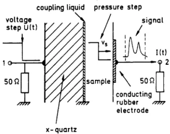
The key for the understanding of the charge and polar-ization properties in polymer lms is the measurement of the their spatial distribution after and preferentially also during the poling process. For this purpose, dier-ent techniques were developed around 1980 which are reviewed in [17]. Here we describe the so called PPS (piezoelectically generated pressure step wave) method [18]. As shown in Fig.2 a pressure step generated by a quartz crystal propagates into the polymer lm. The resulting signal detected with a wide band oscilloscope is directly proportional to the polarization plus the in-tegral over the charge density. By a modication of the setup shown in Fig.2 it is even possible to study the evolution of the polarization during the poling process, i.e. in-situ. Here the PVDF sample is covered with a thin PET lm which carries the poling electrode.
Figure 2. A schematic sketch of the PPS setup [18].
III Results and Discussion
III.1 Charge injection during poling Whereas in charging carnauba wax heterocharge dom-inates homocharge [5], the poling process in PVDF in general is accompanied by charge injection.
zero voltage at the sample, see Fig. 4, the dipole orien-tation relaxes resulting in the release of homocharges as excess charge between sample surface and polarization zone which slowly decays within some 100s. For com-parison, the PPS signal during poling polyvinylchloride
(PVC) is shown in Fig. 5 [7]. In this case no charge injection takes place, but after approx. 3 hours charge extraction from the bulk towards the surfaces can be observed in the form of heterocharge as indicated by the increasing PPS signal near the sample boundaries.
Figure 3. Development of inhomogeneous polarization proles during poling of PVDF with low eld strengths [19]: a) E = 40MV/m; b) E = 80MV/m.
Figure 4. Development of PPS signal after short-circuit of the electrodes: excess charge exists near the inner sample boundaries [21].
Figure 5. Polarization development during the application of an electric eld of 50 MV/m to an 80 (m ) thick PVC
lm at 75C [7]. After approx. 1h the polarization near
the boundaries of the sample increases indicating charge ex-traction from the bulk of the PVC.
dur-ing poldur-ing with,60MV/m for 20000s [21]. While the polarization near the lm boundaries does not change its direction, polarization inversion is observed in the center of the sample. It is important to notice that this inversion is possible even though the reverse eld is well below the coercive eld and the prepoling eld. Without charge injection and charge trapping at the po-larization zone boundaries a homogenous popo-larization decay should have been expected.
Figure 6. Formation a trimorph structure after poling pre-polarized PVDF-lms with an opposite eld [21].
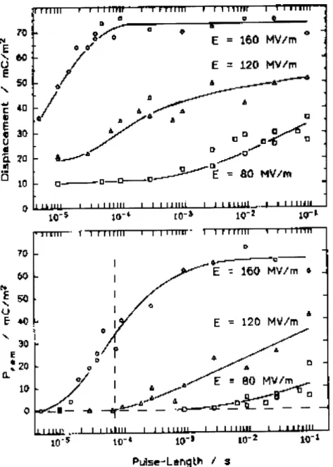
Not only the polarization development during poling, but also the polarization stability is aected strongly by the injected charges [22]. Fig. 7 compares the dielectric displacement during poling and the remanent polariza-tion measured afterwards of two dierently contacted P(VDF-TrFE) samples at identical eld strengths. One sample was directly contacted with evaporated metal electrodes, at the other sample the eld was applied via blocking electrodes made of polyethylenetherephtalate (PET). Since PET is a very good insulator, charge in-jection in the P(VDF-TrFE) was prevented in the latter case. As shown in Fig. 7a the dielectric displacement during poling is the same for both samples indicating equal eld strengths. But after removing the external
eld the polarization in the sample with blocking elec-trodes decays much more rapidly resulting in nearly zero remanent polarization (Fig.7b). This shows that injected charges are somehow needed for the stabiliza-tion of the polarizastabiliza-tion in PVDF and its copolymers.
Figure 7. Top: Dielectric displacement measured during poling with and without blocking electrodes. Bottom: Po-larization distributions after poling with and without block-ing electrode [22].
III.2 Dipole (and charge) dynamics
Additional information about the charge-dipole inter-action can be revealed if the polarization and depolar-ization dynamics are studied. Similar to the experi-ments of Gross in carnauba wax [1, 5] where the hete-rocharge showed faster decay than the homocharge, our measurements show that the dipoles are reaching their equilibrum faster than the charges in PVDF.
of the polarized region and thus play an important role for the polarization stabilization. In this case a time delay between immediate dipole orientation and polar-ization stabilpolar-ization can be expected because of the lim-ited charge injection at the electrodes. In contrast to this a polarization stabilization by a pure dipole-dipole interaction should result in immediate correspondence of momentary and permanent polarization. But in fact a signicant time delay has been observed in short time polarization experiments with unpolarized and prepo-larized PVDF [23] and P(VDF-TrFE) [24] lm material. In the prepolarized material polarization reversal has
been studied. As an example, Fig. 8 shows the results obtained by poling unpolarized P(VDF-TrFE) lms at dierent eld strengths. While at 10,5s a clearly signif-icant dipole orientation is achieved at least at the higher elds, no permanent polarization can be observed. Af-ter longer poling times, permanent polarization remains after switching o the eld, but is always delayed with respect to the dielectric displacement by a time fac-tor of 2 to 3. A similar behaviour has been observed in switching experiments [24] and also for pure PVDF [23].
Charge-dipole interaction aects not only the temporal polarization behaviour during poling but also during thermal depolarization with short heat pulses [25]. By some improvements of the PPS apparatus it was possi-ble to apply heat pulses with a temperature dierence of about 20C within approx. 10ms to our samples and to measure the resulting polarization with a repetition rate of approx. 400 s,1. Fig. 9 shows the polariza-tion response to such a short heat pulse. The polar-ization follows the temperature without delay as to be expected for a pyroelectric material, but with a much higher amplitude as could be calculated from the pyro-electric coecient of PVDF. This anomalous behaviour is called the short-time-pyroelectricity of PVDF. It can be understood if during such a heat pulse the dipoles loose their orientation but the charges trapped at the boundaries of the previously polarized crystallites are not able to leave their positions in the short time avail-able. Then the dipoles can be realigned in the eld of the remaining charges. Realignment of dipoles in the eld of trapped charges is also the reason for the anomalous recovery of polarization after cooling down PVDF lms which had been thermally depolarized near the melting point [26].
Figure 9. PPS Signal during a short heat-pulse [25] showing the short time pyroelectric eect.
III.3 The charge trapping model
It is obvious that for the stabilization of a permanent and macroscopic dipole orientation in PVDF a
spe-cic mechanism is required as for hard ferromagnetism. In the case of magnets the dipole-dipole interaction plays an important role along with a strong crystal eld anisotropy, domain wall pinning and a high activation energy for thermal domain wall creation. In the case of electrets an additional stabilization mechanism is pos-sible by trapping of real charges at the surfaces of the polarized crystallites. These charges not only compen-sate the dipoles reducing their external stray eld but also charges and oriented dipoles are mutuallyattracted by electrostatic forces.
Our measurements described above show the necessity of charge injection for polarization stabilization and the alignment of the injected charges at the polarized re-gion. This leads to the conclusion [18], that the polar-ization stability in PVDF is mediated by the trapping of injected charges in coulomb traps at the boundaries of the polarized crystallites1. This charge trapping is illustrated in Fig. 10 for the two possible cases of pure polarization compensation and complete neutralization. For pure compensation, trapped charges are located at the crystallites near the sample boundaries requiring signicantly less charges than for a complete neutraliza-tion where each individual crystallite even in the bulk of the sample is locally compensated.
Figure 10. Illustration of polarization stabilization in the charge trapping model. Left side: pure compensation. Right side: neutralization.
We were also able to simulate the polarization stabi-lization by charge trapping with a simple mechano-magnetic model as shown in Fig. 11 [27]. As expected for PVDF the pure dipole-dipole interaction is not su-cient for the stabilization of a homogeneous dipole ori-entation (top subgure) whereas \trapped charges at 1For ions as charge carriers as implied by some later discussed experiments, not only electrostaticattration but also an at least partly
crystallite surfaces" stabilize the polarisation (bottom subgure).
Figure 11. Illustration of polarization stabilization by charge trapping with a magneto-mechanical model. The charges and dipoles are simulated by small magnets appropi-ately mounted on plastic oating on an air cushion. The \dipoles" are formed resembling the PVDF chain dipoles and can rotate around a xed center whereas the \charges" can move freely. Top: Without \charges" the \dipoles" are randomly oriented. Bottom: With \charges" present at the boundaries the \dipoles" are all aligned along one direction [6].
III.4Depthand localizationof thecharge traps
Although it is quite clear from the above stated re-sults, that injected charges trapped at the boundaries of the polarized crystallites play a crucial role for the polarization stabilization in PVDF, the microscopic na-ture of the charge traps is yet beyond our knowledge. Two steps towards this goal are the investigation of
the depth of the traps, i.e. the binding energies of the charges and of their spatial distribution depending on the poling conditions [28].
Binding energies can be examined by thermally stim-ulated discharge or depolarization measurements [11]. For the analysis of the broad energy distributions present in PVDF it was however necessary to develop a special mathematical technique [29]. The result of ther-mal depolarization measurements evaluated this way shows Fig. 12 [28]. It is clearly visible, that PVDF lms poled at low eld strengths exhibit one maximum in the energy distribution around 1,7eV whereas in lms poled at high elds the typical binding energy is 2,3eV. Samples poled at intermediate elds show a mixture of both cases. These binding energy values agree well with the observed high long-time-stability of the polar-ization.
Figure 12. Binding energies of the charge traps in PVDF lms poled at dierent eld strengths [28].
contrast to this, for complete neutralization, i.e. com-pensation of each individual crystallite, the amount of necessary charge is much higher. Fig. 13 [28] shows that for PVDF poled at high elds the condition for pure compensation Q = PA is almost fullled, whereas at lower elds signicantly more charge is injected dur-ing poldur-ing implydur-ing at least partial neutralization.
Figure 13. Neutralization or compensation? Charge bal-ance for PVDF lms poled at dierent eld strenghts (:
E=180MV/m,4: E=100MV/m andtu: E=80MV/m) [28]. These measurements show that the poling conditions have strong inuence on the formation of the charge traps. At high elds the dipole orientation is completed before a signicant amount of charge is injected which results in trapping near the sample surface with high binding energies. In this case the dipoles in the cen-ter of the sample are not locally neutralized by trapped charges and should therefore be easier to depolarize. This indeed has been observed in dierent experiments. For example, after reverse poling a prepolarized PVDF lm, see Fig. 6, the polarization is inverted in the sam-ple center. Also if a prepolarized PVDF lm is im-mersed in a polar solvent like acetone, the polarization decreases stronger in the sample center [30]. At low pol-ing eld strenghts a local eld enhancement by charge penetration into the bulk of the material is necessary in order to reach the coercive eld needed for dipole orientation. This results in strong charge injection and
in trapping at lower binding energies at possibly less complete oriented dipoles.
Ionic nature of the injected charges Another question is whether the charges in PVDF are electrons or ions, and if the latter, which type of ions. Generally, both types of carriers can be found in poly-mers [31]. The decrease of electrical conductivity with increasing hydrostatic pressure [31, 32] indicates that in PVDF ionic conduction is present. Ions can also be stronger bound in coulomb traps than electrons. The blocking experiments show that the ionic charges have to be created at the electrodes during the application of the poling eld. A nal test for ion generation and conduction should however also yield informationabout the polarity and type of ions as well as on the trapping process.
Figure 14. Hydrogen uoride (HF) gas emission during pol-ing a 25 m thick PVDF lm covered with a porous gold
electrode with a voltage of up to 2,5 kV [38, 37]. The volt-age is increased rst linearly up to its maximum value, then held constant and nally switched to zero. In the rst two stages the gas emission follows the poling voltage. Addi-tionally, immediately after shortening more gas is emitted during the so-called \zero eld emission".
an additional amount of gas is liberated. The origin of this so called zero-eld-emission can be elucidated from the comparison of its time development with the polar-ization distributions measured after poling as shown in Fig. 15. The larger the distance between the polar-ization maximum and the permeable electrode through
which the gas leaves the sample is, the more delayed is the peak of the zero-eld emission. Therefore the source of the zero-eld emission must be the polarized region and it can be concluded that it results from the detrapping of ions from shallow traps and subsequent gas formation and diusion.
Figure 15. Left side: The HF zero eld emission depending on lm thickness and polarity at T=110C [34]. The poling eld
of 100 MV/m was shortened at t=72 s (dotted line) within 40 ms. Right side: Mean polarization distributions measured after poling. The permeable gold electrode is always on the left side (dotted line). a) PVDF 9m, positive polarity of the
permeable gold electrode, b) PVDF 9m, negative polarity, c) PVDF 25m, positive polarity, d) PVDF 25m, negative
polarity.
Additionally to HF, hydrogene (H2) and uorine (F2) gas are created during poling of PVDF at the negative and the positive electrode, respectively [28]. A detailed analysis of the gas emission data shows that the H2 and F2 gas emission is a result of the electrochemical creation of H+ and F, ions and their transport dur-ing poldur-ing. The strong formation of HF durdur-ing poldur-ing [35] which was also found in some independent mea-surements [36] can be attributed to a zipper-like chain reaction at the polymer chain catalyzed by F,-ions [37, 35]. The polyene sequences resulting from this reac-tion can be detected using raman spectroscopy. This is evident from the growth of two raman lines around 1515 cm,1 and 1118 cm,1 with increasing poling strength in Fig. 16.
Poling PVDF in high electrical eld the injected homo charges are only sucient for the initial compensation at the sample boundaries. The resulting additional pro-duction of HF during poling possibly provides the
ex-cess of H+ and F, ions necessary to develop a neutral-ization of all polarized crystallites in the sample inte-rior.
IV Summary
Figure 16. Raman spectra of poled and unpoled 25m thick
PVDF lms [37]. Sample a): poled 24h with 80 MV/m at 60C; sample b): poled 22h with 80 MV/m at 60C; sample
c): poled 4h with 80 MV/m at 80C; sample d): unpoled:
24h at 66C in vacuum; sample e): completely untreated.
The spectra are normalized with respect to the line at 1430cm,1, which can bei attributed to a CH
2-deformation
vibration.
V Acknowledgements
The results presented in this review originate from a large number of diploma and Phd thesis' by (in al-phabetical order) D. Appel, E. Bihler, W. Burger, E. Brazel, B. Dehlen, G. Eberle, D. Gunther, M. Haardt, K. Holdik, J. Kringler, B. Kussner, M.-A. Maushart, I. Muller, G. Neumann, H. Schmidt, M. Schmidt, M. Selle and M. Womes. The work was in most parts nancially supported by the Deutsche Forschungsge-meinschaft. We also would like to thank our colleagues G.M. Sessler, R. Gerhard-Multhaupt, A.S. DeReggi, J. West and B. Gross for their fruitful and inspiring collaboration.
References
[1] B. Gross, Experiments on electrets,Phys. Rev.66, 26
(1944).
[2] B. Gross, L. Ferreira Denard,On permanent charges in solid dielectrics, I. dielectric absorption and temperaure eects in carnauba wax,Phys. Rev.67, 253 (1945).
[3] B. Gross, Charge Storage in Solid Electrets, Elsevier Publ. Comp., Amsterdam London New York (1964).
[4] B. Gross,Electret Research- Stages in its Development,
Proc. 5th Int. IEEE Symp. Electrets, Heidelberg, 9 (1985).
[5] B. Gross, On permanent charges in solid dielectrics, II. surface charges and transient currents inc carnauba wax,J. Chem. Phys.17, 866.
[6] B. Gross, R.J. de Moraes,Polarization of the electret,
J. Chem. Phys.37, 710 (1962).
[7] K. Holdik, Ladungs- und Polarisationsdynamik in Polymerlmen,PhD Thesis (in german), University of Stuttgart, 1985.
[8] H. Kawai,The piezoelectricity of poly(vinylidene uo-ride),Jpn. J. Appl. Phys.8, 975 (1969).
[9] G. M. Sessler, D. K. Das-Gupta, A. S. DeReggi, W. Eisenmenger, T. Furukawa, J. A. Giacometti, R. Gerhard-Multhaupt,Piezo- and Pyroelectricity in Elec-trets, Caused by Charges, Dipoles or both?, IEEE Trans. Electr. Insul.27, 872 (1992).
[10] A. J. Lovinger, Poly (vinylidene uoride),In: D. C. Basset(ed.), Developments in Crystalline Polymers, J. Appl. Sci.,1, chapter 5, (1982).
[11] G. M. Sessler (Ed.), Topics in Applied Physics: Elec-trets, 2nd Ed.,Springer, Berlin Heidelberg New York, 1987
[12] G. Eberle, H. Schmidt, W. Eisenmenger, Piezoelectric Polymer Electrets,IEEE Trans. Diel. Electr. Insul. 3,
624 (1996).
[13] D. Naegele, D. Y. Yoon, Orientation of crystalline dipoles in poly(vinylidene uoride) lms under electric eld,Appl. Phys. Lett.33, 132 (1978).
[14] R. G. Kepler, R. A. Anderson, Ferroelectricity in polyvinylidene uoride,J. Appl. Phys.49, 1232 (1978).
[15] J. P. Luongo, Far-Infrared Spectra of Piezoelectric Polyvinylidene Fluoride,J. Pol. Sci.10, part A-2, 1119
(1972).
[16] H. Sussner, K. Dransfeld, Importance of the metal-polymer inerface for the piezoelectricity of polyvinyli-dene uoride, J. Polym. Sci. Polym. Phys. 16 529
(1978).
[17] R. Gerhard-Multhaupt, Electrets: Dielectrics with quasi-permanent chare or polarization, IEEE Trans. Electr. Ins.22, 531 (1987).
[18] W. Eisenmenger, M. Haardt, Observation of charge compensated polarization zones in polyvinylideneuo-ride (PVDF) by piezoelectric acoustic step-wave re-sponse,Solid State Comm.41, 917 (1982).
[20] A. Becker, M. Stein, B. Jungnickel, Dependece on su-permolecular structure and on charge injection condi-tions of ferroelectric switsching of PVDF and its blends with PMMA,Ferroelectrics,71, 111 (1995).
[21] G. Eberle, B. Dehlen, W. Eisenmenger,Time develop-ment of multiple polarization zones in PVDF, Ultra-sonics Symposium Proceedings, 1, 529 (1993).
[22] E. Bihler, G. Neumann, G. Eberle, W. Eisenmenger,
Inuence of charge injection on the formation of rema-nent polarization in P(VDF-TrFE) copolymers,IEEE Annual Report Conf. Electr. Insul. Diel. Phenom. 1990, Piscataway, 140 (1990).
[23] M. Womes, E. Bihler, W. Eisenmenger, Dynamics of polarization growth and reversal in PVDF lms,IEEE Trans. Electr. Ins.24, 461 (1989).
[24] G. Eberle, E. Bihler, W. Eisenmenger, Polarization dynamics of P(VDF-TrFE) copolymers,IEEE Trans. Electr. Ins.26, 69 (1991).
[25] B. Dehlen, B. Kussner, G. Eberle, W. Eisenmenger,
Heat pulse depolarization and short time pyroelectric-ity of PVDF and copolymer,Proc. 9th Int. IEEE Symp. Electrets, 925{930, Piscataway (1996).
[26] G. Eberle, W. Eisenmenger, Thermal Depolarization of PVDF: Anomaly at 180C,IEEE Trans. Electr. Ins. 27, 768 (1992).
[27] B. Dehlen,Raumliche und energetische Verteilung der gebundenen Ladungen in PVDF und in dem Copolymer P(VDF-TrFE),PhD Thesis (in german), University of Stuttgart, 1998.
[28] W. Eisenmenger, B. Dehlen, H. Schmidt, The role of charges for polarization stability in PVDF,to be pub-lished, 1998, [27, 37].
[29] B. Kussner, B. Dehlen, G. Eberle, W. Eisenmenger,
inding Energies of Trapped Charges in PVDF and LBP(VDF/TrFE), Proc. 8th Int. IEEE Symp. Elec-trets, Piscataway, 594{599 (1994).
[30] B. Dehlen,Inuence of solvents on the polarization dis-tribution in PVDF,IEEE Annual Report Conf. Electr. Insul. Diel. Phenom. 1992, Piscataway, 172{177 (1992). [31] M. Ieda,Electrical conductionand carrier traps in poly-meric materials, IEEE Trans. Electr. Insul. 19, 162
(1984).
[32] J. Kringler, Druckabhangigkeit der Leitfahigkeit von Polyvinylidenuorid (PVDF),Thesis (in german), Uni-versity of Stuttgart, 1984.
[33] E. Bihler, K. Holdik, W. Eisenmenger,Electric Field-Induced Gas Emission From PVDF Films, IEEE Trans. Electr. Insul. EI-22, 207 (1987).
[34] H. Schmidt, G. Eberle, W. Eisenmenger, Charge de-trapping in PVDF observed by eld induced gas emis-sion, IEEE Annual Report Conf. Electr. Insul. Diel. Phenom. 1995, Piscataway, 626 (1995).
[35] H. Schmidt, W. Eisenmenger,Internal charge genera-tion in polyvinylidene uoride during poling oberved by raman spectroscopy,to be published, 1998.
[36] N. Tsutsumi, G. T. Davis, A. S. DeReggi,Protonation of dyes in ferroelectric copolymer of vinylidene uoride and triuoroethylene,Polym. Comm.32, 113 (1991).
[37] H. Schmidt, Ionische Ladungstrager im piezoelek-trischen Polymer PVDF,PhD Thesis (in german), Uni-versity of Stuttgart, 1997.
![Figure 3. Development of inhomogeneous polarization proles during poling of PVDF with low eld strengths [19]: a) E = 40MV/m; b) E = 80MV/m.](https://thumb-eu.123doks.com/thumbv2/123dok_br/18978618.456205/3.918.210.713.237.536/figure-development-inhomogeneous-polarization-proles-poling-pvdf-strengths.webp)
![Figure 6. Formation a trimorph structure after poling pre- pre-polarized PVDF-lms with an opposite eld [21].](https://thumb-eu.123doks.com/thumbv2/123dok_br/18978618.456205/4.918.500.835.205.751/figure-formation-trimorph-structure-poling-polarized-pvdf-opposite.webp)
![Figure 9. PPS Signal during a short heat-pulse [25] showing the short time pyroelectric eect.](https://thumb-eu.123doks.com/thumbv2/123dok_br/18978618.456205/6.918.111.460.610.893/figure-pps-signal-short-pulse-showing-short-pyroelectric.webp)
![Figure 12. Binding energies of the charge traps in PVDF lms poled at dierent eld strengths [28].](https://thumb-eu.123doks.com/thumbv2/123dok_br/18978618.456205/7.918.480.810.490.894/figure-binding-energies-charge-traps-pvdf-dierent-strengths.webp)
![Figure 13. Neutralization or compensation? Charge bal- bal-ance for PVDF lms poled at dierent eld strenghts ( : E=180MV/m, 4 : E=100MV/m and t u : E=80MV/m) [28].](https://thumb-eu.123doks.com/thumbv2/123dok_br/18978618.456205/8.918.110.461.268.621/figure-neutralization-compensation-charge-pvdf-poled-dierent-strenghts.webp)
![Figure 15. Left side: The HF zero eld emission depending on lm thickness and polarity at T=110 C [34]](https://thumb-eu.123doks.com/thumbv2/123dok_br/18978618.456205/9.918.206.711.243.602/figure-left-hf-zero-emission-depending-thickness-polarity.webp)
![Figure 16. Raman spectra of poled and unpoled 25 m thick PVDF lms [37]. Sample a): poled 24h with 80 MV/m at 60 C; sample b): poled 22h with 80 MV/m at 60 C; sample c): poled 4h with 80 MV/m at 80 C; sample d): unpoled:](https://thumb-eu.123doks.com/thumbv2/123dok_br/18978618.456205/10.918.110.461.88.378/figure-raman-spectra-unpoled-sample-sample-sample-unpoled.webp)
