*e-mail: [email protected]
Influence of Welding Parameters and Post-weld Aging on Tensile Properties
and Fracture Location of AA2139-T351 Friction-stir-welded Joints
Umberto Prisco*, Antonino Squillace, Antonello Astarita, Carla Velotti
Department of Materials and Production Engineering, University of Napoli Federico II, Piazzale Tecchio, 80, 80125 Napoli, Italy
Received: January 22, 2013; Revised: March 20, 2013
Tensile properties and fracture location of AA2139-T351 friction stir welded joints are studied in the as-welded and post-weld aged condition. The experimental results show that when the joints are free of welding defects, they fail on the advancing side of the HAZ exhibiting a large amount of plastic deformation. When the revolutionary pitch exceeds a threshold value, some micro-defects are formed in the weld nugget due to insufficient heat input. In this case, the joints fail near the weld center, and the fracture occurs in a mixed mode, both ductile and brittle. However, being less ductile, post-weld aged joints are less defect-tolerant and, then, they fracture closer to the weld center, showing a reduced elongation at fracture and an UTS within the order of magnitude of the as-welded joints.
Keywords: welding parameters, AA2139-T351, friction stir welding, post-weld ageing, tensile properties, fracture location
1. Introduction
Friction stir welding (FSW) is a solid state joining method especially fit for alloys, as aluminium ones1,2,
difficult to be fusion welded without causing cracks3,4,
porosity or distortion5,6. In particular, earlier studies7-11
showed that it is very suitable for heat-treatable aluminum alloys12,13 which present all the abovementioned problems
at the utmost degree14.
So far, many studies have been carried out on FSWed joints after a heat treatment to assess the properties of the weld structure. In particular, in the 2xxx-series, the following alloys were friction stir welded to compare the mechanical properties of the joints in as-welded and post-weld aged condition: 2219-O15, 2219-T8716, 2017-T35117,
and 2024-T418.
It was found that the post-weld aged 2219-T87 FSWed joints showed superior fatigue performance compared to electron beam and gas tungsten arc welded joints. This was mainly due to the formation of very fine, dynamically recrystallized grains and uniform distribution of fine precipitates in the weld region16. Chen et al.15 showed that
the tensile strength of FSWed joints of 2219-O aluminum alloy can be significantly improved by the post-weld heat treatment process, and the strength increases with increasing welding speed. The post weld heat treatment also influenced the fracture locations of the joints, and all the heat-treated joints fractured in the weld zone. These results can be explained by the micro-hardness profiles and the inner structure of the joints. Aydin et al.18 demonstrated
that the T6 (190 °C-10 h) ageing treatment after FSW was more beneficial than other heat treatments in enhancing the mechanical properties of 2024-T4 joints. However, the T6 heat treatment led to significant ductility deterioration in
the joint due to an abnormal coarsening of the grains in the weld zone, which resulted in a drop in micro-hardness at the weld zone compared to the base material of the joints.
However, FSW of the 2139-T351 completely lacks of scientific studies comparing the tensile properties and fracture location of the as-welded and post-weld aged joints.
Among the 2xxx series heat-treatable aluminum alloys, 2139 has lately attracted much attention due to its improved hardenability by ageing between 150 and 200 °C8. The
primary strength-providing phase of Al-Cu alloys is the tetragonal structure of θ’ phase. The addition of small quantity of Ag and Mg to the alloy, as for the 2139, brings about the formation of a fine and uniformly dispersed phase, designated as Ω, which forms hexagonal-shape plate-like precipitated on matrix {111}Al planes. The presence of Ω
on the principal slip plane {111}Al is the main reason for the useful mechanical properties of the 2139 after artificial ageing. Mg is known to be crucial for the formation of the Ω
phase in Al-Cu alloys, and Ag accelerates its precipitation. Indeed, the strong interaction between Ag and Mg results in the generation of Mg-Ag clusters which act as sites for the nucleation of Ω. Moreover, Ω is more stable than θ’ at the usual aging temperatures (≤ 200 °C), indicating that the 2139 exhibits excellent mechanical strength up to 200 °C19,20.
In T351 condition, the 2139 is hardened by the Cu GP-zone formation, as demonstrated21. After T8 treat
treatment, i.e., aging at 175 for at least 5 hours, the 2139-T351 is brought in T851 condition, where Ω is the primary strengthening phase.
friction stir welded joints. Comparison between as-welded and post weld aged joints is carried out using tensile properties, hardness, weld macrostructure and fracture location as function of the revolutionary pitch (RP).
2. Experimental Procedure
The base material used in this study is a 2139 aluminum alloy (2.81 g/cm3) supplied by Alcan as 3.2 mm thick rolled
sheets. The chemical composition of the alloy, determined in laboratory by means of spectrochemical analysis according to ASTM E716-10, is reported in Table 1. The AA2139 sheets were cut into rectangular plates of 200 × 80 mm and, then, heat treated to T351, i.e. solution treated at 540 °C for 8 hours, quenched into ice water, stress relived by stretching on the order of 1.5% and naturally aged for 100 days.
Afterwards, 18 couples of 2139-T351 welding samples were butt-welded, along the rolling direction using a FSW machine. The FSW was performed in position-controlled mode with a vertical interference between the shoulder and the sheet surface set to ∼0.1 mm (i.e., tool plunge depth
∼3.1 mm) to attain the suitable frictional contact. The designated tool geometry is in Figure 1. The tilt angle was 2°. The adopted welding parameters are listed in Table 2, where for each couple of welding and rotation speed the corresponding value of the RP is reported. Two welds were performed for each RP. One was analysed in the as welded condition; the other was post-weld treated; in particular, 9 joined samples, each for any welding condition, were heat treated to T851 through artificial ageing at 175 for 16 hours. Hereinafter, it will be referred to this joints as post-weld aged joints.
For comparison reasons, a bare 2139-T351 sheet was subjected to the same treatment. All the abovementioned heat treatments were carried out in a vacuum furnace with an attached thermocouple. Thus, at this stage, 2139-T351, 2139-T851, as-welded 2139-T351 joints and post-weld aged joints are available.
The joints were cross-sectioned perpendicular to the welding direction for metallographic analyses and tensile tests. The cross-sections of the metallographic specimens were polished with alumina suspension, etched with Keller’s reagent (150 mL water, 3 mL nitric acid, 6 mL hydrochloric acid and 6 mL hydrofluoric acid) and observed by optical microscopy. Tensile test specimens, with longitudinal axis perpendicular to the welding direction, i.e. in LT orientation with regard to the rolling direction, were extracted from the
welded sheets. The configuration and size of the specimens Figure 1. FSW tool (dimensions in mm).
Table 1. Chemical composition and mechanical properties of AA2139 (median over four specimens, the 80% confidence limits are reported).
Chemical composition [wt%]
Cu Mg Ag Mn Si Fe Ti Zr Zn Ni Cr Al
4.80 ± 0.31 0.43 ± 0.04 0.31 ± 0.07 0.27 ± 0.09 0.06 ± 0.08 0.06 ± 0.08 0.06 0.03 <0.01 <0.01 10 ppm Bal.
Mechanical properties, LT
Rp0.2 [MPa]
UTS [MPa]
Elongation [%]
Hardness [HV]
2139-T351 297 ± 12 411 ± 29 22.1 ± 1.9 136 ± 5 2139-T851 428 ± 16 495 ± 34 10.5 ± 1.0 153 ± 6
Table 2. Values of the RP [mm/rev] for each couple of adopted welding parameters.
Welding speed [mm/min]
155 225 300
Rotation speed [rpm]
900 0.167 0.250 0.333
700 0.214 0.321 0.429
500 0.300 0.450 0.600
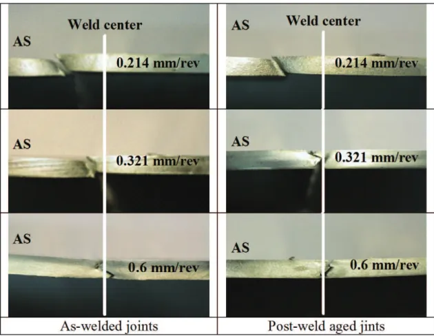
Figure 2. Cross-sections of representative joints welded at the different process parameters (AS = advancing side).
Figure 3. Experimental plan showing the combinations of process parameters; the boundary of sound joints is reported.
and 2139-T851 were also evaluated using four tensile specimens, see Table 1.
3. Results and Discussion
3.1.
Experimental results
3.1.1. Weld macrostructure
Figure 2 shows the typical cross-sections of the joints welded with different RP. The classical asymmetrical structure of the weld bead, result of the asymmetric metal flow at the advancing and a retreating side, is clearly visible.
Figure 3 shows, in the adopted FSW condition, the window of welding parameters which results in sound joints, i.e. joints free of macroscopically defects.
Outside the window of sound joints, three types of macro-defects, already reported in previous studies22, are
observed depending on the FSW parameters.
1. A large mass of burr, due to the excessive softening of the metal caused by the surplus of heat input during the FSW at lower welding speed and higher rotation speed, i.e. at 150 mm/min and 900 rpm (RP = 0.167 mm/rev). 2. A groove-like defect, called tunnel, always located on
the advancing side, ensued from the insufficient heat input, visible in the center-bottom and right-bottom side of the sound joints window in Figure 3 (at RP = 0.45 and 0.6 mm/rev).
3. A cavity produced by the abnormal stirring, observed at higher welding speed and rotational speed (300 mm/min and 900 rpm, RP = 0.333 mm/rev), namely in the right upper side of the sound joint window, as shown in
Figure 3. In this case, due to the discontinuous flow of material and to the temperature difference between the top and bottom of the sheet, the upper part of the stir zone on the advancing side shows a contour totally dissimilar from the others, see Figure 2.
Starting from 0.333 mm/rev, besides the abovementioned macro-defect, micro-voids become evident in the nugget of the joins, see Figure 2. Their size and number is enhanced by the lack of adequate heat input, which is very significant for RP greater than this value.
3.1.2. Tensile properties
Figure 4 reports the tensile properties of the as welded and post-weld aged joints at different RP; in particular, Rp0.2, the 0.2% proof stress, UTS, the tensile strength, and the elongation at break are shown. From the figure, it is evident that all the as-welded joints present tensile properties poorer than those of the base material (see Table 1). Particularly, the elongation at break is significantly smaller than that of the base material, with a maximum which is around 12% against the 22.1% shown by the base material.
the elongation at break. These results point out that, just as experienced by other heat-treatable aluminum alloys5,10, the
2139-T351 aluminum softened during the FSW process. The welding parameters significantly influence the softened levels of the tensile properties.
Comparing the tensile properties of the as-welded joints with those of the post-weld aged joints at different RP, Figure 4, a contradictory picture seems to emerge. While the 0.2% proof stress of the post-weld aged joints are all higher than those of the as-weld joints (although lower than those of the 2139-T851), their UTS are of the same order of magnitude of the as-welded joints, as it is evidenced by the overlapping of the confidence intervals, which means that the UTS variation between as-welded and post-weld aged joints is not statistically significant. In addition, the elongation of the post-weld aged joints is dramatically lower than that of the as-welded ones. Figure 4 shows that Rp0.2 and UTS of the post-weld aged joints are quite constant up to 0.3 mm/rev and, subsequently, decrease with the RP, while their elongation at break just decreases as the RP increases. However, as for the as-welded joints, the elongation at break of the post-weld aged joints undergoes a sharp decrement starting from 0.333 mm/rev.
3.1.3. Fracture locations
Figure 5 shows representative photographs of the fractured specimens at different RP. In Figure 6, the fracture location is characterized by the distance between the fracture surface and the weld center.
All the joints fail on the advancing side. This suggests that the tensile properties on the advancing side are weaker than those on the retreating side of the joints. All the fractures are characterized by a heterogeneous deformation mainly confined in the weld zone, as already observed for other friction stir welded aluminum alloys10. The fracture
locations change with the FSW parameters: increasing the RP, the fracture location of the joints progressively moves towards the weld center, both for the as-welded and the post-weld aged joints. Post-weld aged joints fracture much closer to the weld center at each RP, see Figure 6. Actually, the first three points in Figure 6 show large overlapping of the confidence intervals. This means that the variation in fracture location between as-welded and post-weld aged joints is not statistically significant. However, for higher RP this difference becomes very important.
For RP lower or equal to 0.3 mm/rev, the fracture surface of the as-welded joints is located in the HAZ of the advancing side, and fracture parts undergo a large amount of deformation, typical of a ductile fracture. This is confirmed by the inclination of the fracture propagation path at about 45° to the normal stresses. Above 0.3 mm/rev, the fracture location quickly moves towards the weld center and it always occurs in the nugget zone. Moreover, for these values of the RP, the fracture propagation follows a zig-zag path, see Figure 5, characterized by low strains.
Fracture surface of the post-weld aged joints is located in the HAZ for RP lower or equal to 0.25 mm/rev, otherwise it is in the nugget zone. In this case, as before, the fracture propagation shows a zigzag aspect while the UTS at different RP, behaviour already described in previous
studies6,7. The maximum R
p0.2 is recorded at 0.3 mm/rev; its
value is 282 MPa, corresponding to 94% of that of the base material. The maximum UTS is observed at 0.25 mm/rev; its value is 397 MPa, equal to 96% of that of the base material. For RP bigger than 0.333 mm/rev, all the tensile properties significantly decrease to low levels, especially the UTS and
Figure 5. Typical fracture locations of the as-welded and post-weld aged joints.
involved material seems to have undergone considerably low deformation before fracture.
3.2.
Discussion
Tensile properties and fracture locations are based on the internal structures of the joints, when the joints are defect-free, otherwise welding defects can prevail on the fracture mechanism. Indeed, stress and strain concentration occurs in
the lower-strength zone of the joint, when it is subjected to a tensile loading, and, therefore, the joint fractures in this zone. Microhardness measurements on the joint cross-section both of the as-welded and post-weld aged joints shows the typical hardness distribution of a heat treatable aluminum alloy after FSW9,17. The observed data dispersion agrees
with what has been previously recorded in literature5,10.
for FSWed joints in the 2xxx series. A softened region,
Figure 6. Fracture location of the joints as function of the RP (median over four specimens, the 80% confidence limits are reported).
characterized by hardness degradation and made up by the nugget and the two HAZs, was observed. No statistical significant difference was observed between the hardness of the HAZ at the advancing and retreating sides. However, the HAZ always shows the minimum hardness vales and, then, is the weakest zone in the weld. This means that the tensile properties of the joints are expected to be smaller than those of the base materials. Moreover, the welding parameters strongly affect the hardness of the HAZ, as shown in Figure 7 reporting the HAZ hardness of the joints as function of the RP. It is clear that the HAZ hardness increases with the RP because the heat input, which is the principal responsible of the hardness degradation and grain coarsening in the HAZ, is inversely proportional to the RP12.Very important to note is that the HAZ hardness of the post-weld aged joints is always greater than that of the as-welded ones at each RP23. Then, as-welded joints
are still capable of heat treatment hardening. Of course, post-weld aged joints do not reach the hardness of the 2139-T851, because the heat input of the FSW process lowered the age hardenability of the 2139-T351, due to nugget recrystallization, grain coarsening and diffusion of alloy elements in the HAZ; this partially prevents Mg-Al co-clustering which promotes the precipitation of the Ω
phase during the subsequent heat treatment13. Finally, it is
to be notice that, in the studied RP range, HAZ hardness of as-welded joints increases of about 20%, while that of the post-weld aged joints of about 10%, meaning that the post-weld treatment has also the effect of reducing and redistributing residual stresses, with consequent levelling of the mechanical properties of the joints.
For RP larger than 0.333 mm/rev, micro-voids are observed in the nugget of the joints. They are due to lack of heat input and subsequent problems in the flow of material around the pin; consequently, micro-voids increase in number and size with the RP. These defects can seriously spoil the tensile properties of the joints and affect the fracture location. Naturally, the effect of the observed defects on the fracture mechanism depends on the material tolerance to fracture-initiating defects and ductility is a good measure of this tolerance.
For low RP, being free of defects, the as-welded joints fracture in the HAZ, which is the weakest region in the weld. The occurrence of the fracture on the advancing side is a satisfactory evidence to deduce the smaller tensile strength of the advancing side respect to that of the retreating one. The elongation at break, around 12%, and the fracture propagation, oriented to 45° about the tensile axis, are evidences of a classical ductile cracking mechanism. As the RP increases, the heat input diminishes; hence, the nugget undergoes a reduction in size and the distance between the weld center and the HAZ decreases, as well. As a result, the joints fracture nearer to the weld center. Around a RP equal to nearly 0.333 mm/rev, micro-voids in the middle of the
joints start to become significant upon fracture mechanics. These micro-voids increase in size and number with the RP. Generating a phenomenon of stress intensification, they degenerate the tensile properties of the joints and cause them to break at the weld center; indeed, from this value of the RP the fracture results in the weld center. Then, the tensile properties of the joints become lower and keep decreasing as the RP increases. The elongation at break progressively reduces to approximately 8% while the fracture propagation following the micro-void network describes a zigzag path (particularly evident at 0.6 mm/rev). In this case, the fracture was observed to occur in a mixed mode, both ductile and brittle.
The T8 heat treatment increases the tensile properties of the 2139, but, at the same time, reduces the elongation at break to less than half of that of 2139-T351, see Table 1. It has obviously the same effect on the as-welded joints which increase their 0.2% proof stress and hardness but reduce their ductility compared to the non-aged joints. Hence, post-weld aged joints become much less defect-tolerant than the as-welded ones. The final result of the decreased ductility is that the post-weld aged joints, both when they fracture in the HAZ and nugget, show a reduced elongation at break, with 5% and 1% as maximum and minimum value, respectively. This has a strong effect on the σ-ε curve and, then, on the UTS, which, in spite of the increased Rp0.2 and hardness, show the same order of magnitude observed in the as-welded joints. As before, when located in the nugget zone, the fracture propagation shows a tortuous aspect because the crack follows the defect path and, increasing the RP, the amount of brittle fracture increases.
4. Conclusions
Tensile properties and fracture location of the studied joints are influenced by:
• Asoftenedregion,particularlyevidentintheHAZ,
characterized by degradation of both the hardness and the tensile properties;
• Micro-voids,whosepresencebecometobesigniicant
in the nugget when the heat input starts to become very insufficient, i.e. from RP greater than around 0.333 mm/rev.
References
1. Chien C-H, Lin W-B and Chen T. Optimal FSW process parameters for aluminum alloys AA5083. Journal of the Chinese Institute of Engineers. 2011; 34(1):99-105. http:// dx.doi.org/10.1080/02533839.2011.553024
2. Santiago DH, Lombera G, Urquiza S, Cassanelli A and De Vedia LA. Numerical modeling of welded joints by the “friction stir welding” process. Materials Research. 2004; 7(4):569-574. http://dx.doi.org/10.1590/S1516-14392004000400010 3. Seli H, Awang M, Ismail AIM, Rachman E and Ahmad
ZA. Evaluation of properties and FEM model of the friction welded mild steel-Al6061-alumina. Materials
Research. 2013; 16(2):453-467. http://dx.doi.org/10.1590/
S1516-14392012005000178
4. Grujicic M, Arakere G, Yalavarthy HV, He T, Yen C-F and Cheeseman BA. Modeling of AA5083 material-microstructure evolution during butt friction-stir welding. Journal of Materials Engineering and Performance. 2010; 19(5): 672-684. http:// dx.doi.org/10.1007/s11665-009-9536-1
5. Grujicic M, Arakere G, Yen C-F and Cheeseman BA. Computational investigation of hardness evolution during friction-stir welding of AA5083 and AA2139 aluminum alloys. Journal of Materials Engineering
and Performance. 2011; 20(7):2011-1097. http://dx.doi.
org/10.1007/s11665-010-9741-y
6. Vitiello A and Prisco U. Evaluation of drilling parameters effects on machinability of PM materials using ANOVA.
Powder Metallurgy. 2009; 52(2):164-171. http://dx.doi.
org/10.1179/003258908X334230
7. Serroni G, Squillace A, Prisco U, Bitondo C and Prisco A. Aircraft panels stiffened by friction stir welded extruded parts: mechanical characterization. Metallurgia Italiana. 2011; 103(1):35-39.
8. Bitondo C, Prisco U, Squillace A, Giorleo G, Buonadonna P, Dionoro G et al. Friction stir welding of AA2198-T3 butt joints for aeronautical applications. International Journal of Material
Forming. 2010; 3(1):1079-1082. http://dx.doi.org/10.1007/
s12289-010-0958-y
9. Bitondo C, Prisco U, Squillace A, Buonadonna P and Disonoro G. Friction-stir welding of AA 2198 butt joints: mechanical characterization of the process and of the welds through DOE analysis. International Journal of Advanced Manufacturing Technology. 2011; 53(5):505-516. http://dx.doi.org/10.1007/ s00170-010-2879-9
10. Carrino L, Ciliberto S, Giorleo G and Prisco, U. Effect of filler content and temperature on steady-state shear flow of wood/high density polyethylene composites. Polymer Composites. 2011; 32(5):796-809. http://dx.doi.org/10.1002/ pc.21101
11. Squillace A, Prisco U, Ciliberto S and Astarita A. Effect of welding parameters on morphology and mechanical properties of Ti–6Al–4V laser beam welded butt joints. Journal of
Materials Processing Technology. 2012; 212(2):427-436.
http://dx.doi.org/10.1016/j.jmatprotec.2011.10.005
12. Prisco A, Acerra F, Squillace A, Giorleo G, Pirozzi C, Prisco U et al. LBW of similar and dissimilar skin-stringer joints. part I: process optimization and mechanical characterization.
Advanced Materials Research. 2008; 38:306-319. http://dx.doi. org/10.4028/www.scientific.net/AMR.38.306
13. Prisco U and Polini W. Flatness, cylindricity and sphericity assessment based on the seven classes of symmetry of the surfaces. Advances in Mechanical Engineering. 2010; Article number154287. http://dx.doi.org/10.1155/2010/154287
14. Grujicic M, Arakere G, Hariharan A and Pandurangan B. Two-level weld-material homogenization for efficient computational analysis of welded structure blast-survivability. Journal of Materials Engineering and Performance. 2012; 21(6):786-796.
15. Chen YC, Liu HJ and Feng JC. Effect of post-weld heat treatment on the mechanical properties of 2219-O friction stir welded joints. Journal of Materials Science. 2006; 41:297-299. http://dx.doi.org/10.1007/s10853-005-0640-9
16. Malarvizhi S and Balasubramanian V. Effects of welding processes and post-weld aging treatment on fatigue behavior of AA2219 aluminium alloy joints. Journal of Materials
Engineering and Performance. 2011; 20(3):2011-359.
17. Liu HJ, Fujii H, Maeda M and Nogi K. Tensile properties and fracture locations of friction-stir-welded joints of 2017-T351 aluminum alloy. Journal of Materials Processing Technology. 2003; 142(3):692-696. http://dx.doi.org/10.1016/ S0924-0136(03)00806-9
18. Aydin H, Bayram A and Durgun I. The effect of post-weld heat treatment on the mechanical properties of 2024-T4 friction stir-welded joints. Material & Design. 2010; 31(5):2568-2577. http://dx.doi.org/10.1016/j.matdes.2009.11.030
19. Chang CH, Lee SL, Lin JC and Jeng RR. The effect of silver content on the precipitation of the Al-4.6Cu-0.3Mg alloy.
Materials Transactions. 2005; 46(2):236-240. http://dx.doi. org/10.2320/matertrans.46.236
20. Bakavos D, Prangnella PB, Besb B and Eberlb F. The effect of silver on microstructural evolution in two 2xxx series Al-alloys with a high Cu:Mg ratio during ageing to a T8 temper. Materials Science and Engineering: A. 2008; 491(1-2):214-223. http:// dx.doi.org/10.1016/j.msea.2008.03.014
21. Konno TJ, Hiraga K and Kawasak M. Guinier-Preston (GP) zone revisited: atomic level observation by HAADF-TEM technique. Scripta Materialia. 2001; 44(8-9):2303-2307. http:// dx.doi.org/10.1016/S1359-6462(01)00909-5
22. Kima YG, Fujii H, Tsumura T, Komazaki T and Nakata K. Three defect types in friction stir welding of aluminum die casting alloy. Materials Science and Engineering: A. 2006; 415(1-2):250-254. http://dx.doi.org/10.1016/j. msea.2005.09.072