08 artigo 510
ORIgINAL ARtICLE
1 – PhD in Medicine from the Paulista Medical School, Federal University of São Paulo. Head of the “Prof. Dr. Donato D’Ângelo” Orthopedics and Traumatology Clinic, Hospital Santa Teresa, Petrópolis, RJ, Brazil.
2 – Resident Physician in Orthopedics and Traumatology, “Prof. Dr. Donato D’Ângelo” Orthopedics and Traumatology Clinic, Hospital Santa Teresa, Petrópolis, RJ, Brazil. 3 – PhD. Associate Professor and Head of the Department of Orthopedics and Traumatology, School of Medicine, UFRJ, Rio de Janeiro, RJ, Brazil.
4 – Head of the Foot and Ankle Department, “Prof. Dr. Donato D’Ângelo” Orthopedics and Traumatology Clinic, Hospital Santa Teresa, Petrópolis, RJ, Brazil. 5 – Coordinator of the Foot and Ankle Surgery Service, “Clementino Fraga Filho” University Hospital, UFRJ, and Ipanema Federal Hospital, Rio de Janeiro, RJ, Brazil. 6 – Attending Physician in the Trauma Group, Clinical Hospital, Ribeirão Preto Medical School (FMRP), USP, and Member of the Foot, Ankle and Trauma Group, Specialized Hospital of Ribeirão Preto, São Paulo, SP, Brazil.
Work performed at the “Prof. Dr. Donato D’Ângelo” Orthopedics and Traumatology Clinic, Hospital Santa Teresa, Petrópolis, and at the Petrópolis Medical School, Petrópolis, RJ, Brazil.
Address for correspondence: Av. Roberto Silveira 187, ap. 601, 25685-040 Petrópolis, RJ. E-mail: [email protected] Work received for publication: May 25, 2011; accepted for publication: October 4, 2011.
SAFE LOCALIzATION FOR PLACEmENT OF PERCuTANEOuS
PINS IN THE CALCANEuS
Pedro José Labronici1, Diogo do Nascimento Pereira2, Pedro Henrique Vargas Moreira Pilar2, José Sergio Franco3,
Marcos Donato Serra4, José Carlos Cohen5, Rogério Carneiro Bitar6
ABstRACt
Objective: To determine the areas presenting risk in six zones of the calcaneus, and to quantify the risks of injury to the anato-mical structures (artery, vein, nerve and tendon). Method: Fifty--three calcanei from cadavers were used, divided into three zones and each subdivided in two areas (upper and lower) by means of a longitudinal line through the calcaneus. The risk of injury to the anatomical structures in relation to each Kirschner wire was determined using a graded system according to the Licht classification. The total risk of injury to the anatomical structures
INtRODUCtION
Placement of percutaneous pins in the calcaneus is a relatively common procedure(1,2). Pins are used for introducing the external fixator, traction, frac-ture-reducing distractors, arthroscopic treatments, correction of deformities and reduction of forefoot dislocation(2-6). With this type of procedure, various anatomical structures in the medial region may present a risk of iatrogenic injury. Several studies have sought to define a safety zone by means of radiographs or ca-daveric studies, taking anatomical reference points as the basis(7,8). The aim of this study was to analyze the placement of percutaneous pins from the lateral to the medial region, at six given sites on the calcaneus, in order to observe the risks of iatrogenic injuries to the
nerves, arteries, veins and tendons, and to quantify the likelihood of injuries to the anatomical structures after placement of Kirschner wires in the six zones studied.
MEtHODs
Fifty-three calcanei from cadavers at the Petrópolis Medical School were used. The calcanei were divided into six different zones, as illustrated in Figure 1: zones IA and IB, located on the anterior tuberosity of the calca-neus, from the line of the calcaneocuboid joint to a line in the region of the Gisane angle; zones IIA and IIB, in the region of the body of the calcaneus, from the line of the Gisane angle to the end of the posterior tuberosity of the talus; and zones IIIA and IIIB, located in the region of the posterior tuberosity of the calcaneus (Figure 1).
The authors declare that there was no conflict of interest in conducting this work
this article is available online in Portuguese and English at the websites: www.rbo.org.br and www.scielo.br/rbort
through placement of more than one wire was quantified using the additive law of probabilities and the product law for inde-pendent events. Results: The injury risk calculation according to the Licht classification showed that the highest risk of injury to the artery or vein was in zone IA (43%), in relation to injuries to nerves and tendons (13% and 0%, respectively). Conclusion: This study made it possible to identify the most vulnerable ana-tomical structures and quantify the risk of injury to the calcaneus.
en 2 and 5 mm, i.e. these were considered to present a moderate risk of injury. Wires located at distances of between 5 and 10 mm were classified as risk grade 1, i.e. they were considered to present minimal risk of injury. Kirschner wires located at distances greater than 10 mm were not considered to present any risk of injury and were classified as risk grade 0 (Table 1).
Table 2 presents the mean, standard deviation (SD), median, minimum and maximum of the dis-tances (in mm) of the Kirschner wires from arteries, veins, nerves and tendons, for the six heel zones of the 53 feet, among which 22 (41.5%) were right feet and 31 (58.5%) were left feet.
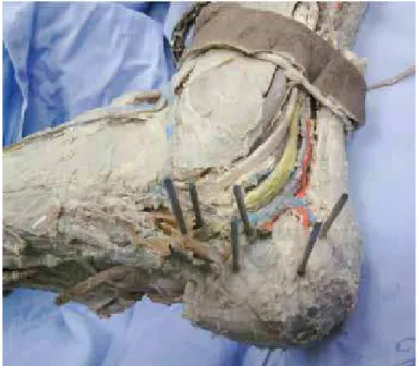
A 2 mm Kirschner wire was placed at the center of each area, from laterally to medially; all the wires were perpendicular to the lateral cortex of the calca-neus (Figure 2). The calcanei were then dissected me-dially to enable measurements (in millimeters) of the distances from the exit point of each Kirschner wire to the following structures: posterior tibial artery and vein, posterior tibial nerve and posterior tibial tendon. The grading system developed by Licht et al(9) was used to determine the risk of injury to the anatomical structures in relation to each Kirschner wire. Wires that were located between 0 and 2 mm from one of the above structures were classified as presenting risk grade 5, i.e. they were considered to present a high risk of injury to the anatomical structures. Risk grade 3 was given to the wires located at distances of
betwe-Figure 1 – Diagram showing the six zones of the calcaneus with the positions of the
Kirschner wires.
Figure 2 – Photograph of the heel of a cadaver with Kirchner wires coming out of
the medial face.
table 1 – Classification system of Licht et al(9) for the risk of injury.
Distance to Kirschner
wire Risk grade
Classification of risk of injury
0 a 2mm 5 Alto
2 a 5mm 3 moderado
5 a 10mm 1 Mínimo
> 10mm 0 Ausente
Source: Petrópolis Medical School.
table 2 – Description of the distances (in mm) of the Kirschner wire from
the comparison point, according to heel zone, in 53 feet.
Heel zone Comparison
point Mean sD Median Minimum Maximum
iA
Artery 3.2 2.1 3 1 10
vein 3.2 2.1 3 1 10
Nerve 4.9 2.8 4 0 13
Tendon 9.3 6.9 7 3 35
IB
Artery 4.3 2.7 4 0 13
vein 4.3 2.7 4 0 13
Nerve 6.0 3.7 5 0 16
Tendon 10.8 7.1 8 3 32
iiA
Artery 5.2 2.9 5 0 16
vein 5.1 3.0 5 0 16
Nerve 6.3 3.2 6 0 16
Tendon 11.5 7.1 9 3 33
IIB
Artery 7.1 3.4 6 0 18
vein 7.1 3.4 6 0 18
Nerve 8.9 5.7 8 1 40
Tendon 14.3 7.4 13 3 36
iiiA
Artery 8.6 4.2 8 0 22
vein 8.7 4.1 8 0 22
Nerve 10.5 4.5 10 1 25
Tendon 16.1 8.0 13 7 40
IIIB
Artery 10.5 4.5 9 1 24
vein 10.6 4.6 9 1 24
Nerve 12.8 5.8 12 2 36
Tendon 19.1 9.5 15 8 50
REsULts
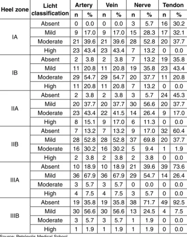
The risk of injury presented by each Kirschner wire in the medial cortex of the calcaneus is demons-trated in Table 3, which presents the frequency (n) and percentage (%) of the Licht classification in relations to arteries, veins, nerves and tendons, according to the six heel zones of the 53 feet.
The likelihood of injuries to the arteries, veins, nerves and tendons in the six zones studies was based on the Licht classification for high risk, as illustrated in Table 4. In the sample of this study, the likelihood of artery injury when a Kirschner wire was placed in zone IA was 0.434 or 43.4%.
table 3 – Description of Licht classification for arteries, veins, nerves
and tendons, according to heel zone, in 53 feet.
Heel zone Licht classification
Artery Vein Nerve tendon
n % n % n % n %
iA
Absent 0 0.0 0 0.0 3 5.7 16 30.2 mild 9 17.0 9 17.0 15 28.3 17 32.1 moderate 21 39.6 21 39.6 28 52.8 20 37.7
High 23 43.4 23 43.4 7 13.2 0 0.0
IB
Absent 2 3.8 2 3.8 7 13.2 19 35.8 mild 11 20.8 11 20.8 19 35.8 23 43.4 moderate 29 54.7 29 54.7 20 37.7 11 20.8
High 11 20.8 11 20.8 7 13.2 0 0.0
iiA
Absent 2 3.8 2 3.8 3 5.7 24 45.3 mild 20 37.7 20 37.7 30 56.6 20 37.7 moderate 23 43.4 22 41.5 14 26.4 9 17.0
High 8 15.1 9 17.0 6 11.3 0 0.0
IIB
Absent 7 13.2 7 13.2 9 17.0 32 60.4 mild 28 52.8 28 52.8 37 69.8 20 37.7 moderate 16 30.2 16 30.2 5 9.4 1 1.9
High 2 3.8 2 3.8 2 3.8 0 0.0
iiiA
Absent 10 18.9 10 18.9 21 39.6 39 73.6 mild 36 67.9 36 67.9 29 54.7 14 26.4 moderate 3 5.7 3 5.7 0 0.0 0 0.0
High 4 7.5 4 7.5 3 5.7 0 0.0
IIIB
Absent 19 35.8 19 35.8 38 71.7 49 92.5
mild 30 56.6 30 56.6 13 24.5 4 7.5 moderate 3 5.7 3 5.7 1 1.9 0 0.0
High 1 1.9 1 1.9 1 1.9 0 0.0
Source: Petrópolis Medical School.
When two wires (W1 and W2) are used, the combined likelihood is given by the additive law of probabilities: Pr(W1 U W2) = Pr(W1) + Pr(W2) – Pr(W1 ∩ W2) (Equation 2.1) where Pr (W1 ∩ W2) is the intersection.
If it is considered that the risk of injury presen-ted by one wire does not interfere with the risk of injury presented by the other, then the probability of intersection is given by the product law for inde-pendent events:
Pr(W1 ∩ W2) = Pr(W1) * Pr(W2) (Equation 2.2). For example, the likelihood of injuring an artery in placing one wire in zone IA (W1) and another in zone IIA (W2) will be 51.9%, as shown in the calcu-lation below:
Pr(W1 U W2) = 0.434 + 0.151 – 0.434 * 0.151 = 0.585 – 0.066
= 0.519 or 51.9%
The additive law (Equation 2.1) can be extended to combinations of three or more events. For three events, the formula is as follows:
Pr(W1 U W2 U W3) = Pr(W1) + Pr(W2) + Pr(W3) – Pr(W1 ∩ W2) – Pr(W1 ∩ W3) – Pr(W2 ∩ W3) (Equa-tion 2.3)
+ Pr(W1 ∩ W2 ∩ W3)
with Pr(W1 ∩ W2 ∩ W3) = Pr(W1) * Pr(W2) * Pr(W3). For example, the likelihood of injuring a vein in placing three wires, among which the first is in zone IA (W1), the second in zone IB (W2) and the third in zone IIA (W3), will be 62.8%, as shown in the calcu-lation below:
Pr(W1 U W2 U W3) = 0.434 + 0.208 + 0.170 – 0.090 – 0.074 – 0.035
+ 0.015
= 0.628 or 62.8%
For four independent events (W1, W2, W3 and W4), the probability is given by the following formula: Pr(W1 U W2 U W3 U W4) =
Pr(W1) + Pr(W2) + Pr(W3) + Pr(W4) (Equation 2.4) – Pr(W1 ∩ W2) – Pr(W1 ∩ W3)– Pr(W1 ∩ W4) – Pr(W2 ∩ W3) – Pr(W2 ∩ W4) – Pr(W3 ∩ W4)
+ Pr(W1 ∩ W2 ∩ W3) +Pr(W1 ∩ W2 ∩ W4) + Pr(W1 ∩ W3 ∩ W4) + Pr(W2 ∩ W3 ∩ W4)
– Pr(W1 ∩ W2 ∩ W3 ∩ W4)
with Pr(W1 ∩ W2 ∩ W3 ∩ W4) = Pr(W1) * Pr(W2) *Pr (W3) * Pr(W4)
For example, the likelihood of injuring nerves in table 4 – Likelihood of injuring arteries, veins, nerves and tendons
according to heel zone.
Heel zone Comparison point
Artery Vein Nerve tendon
iA 0.434 0.434 0.132 0.0
IB 0.208 0.208 0.132 0.0
iiA 0.151 0.170 0.113 0.0
IIB 0.038 0.038 0.038 0.0
iiiA 0.075 0.075 0.057 0.0
IIIB 0.019 0.019 0.019 0.0
DIsCUssION
Meticulous knowledge of the anatomy of the hindfoot is an important prerequisite for planning to place pins and perform open reduction and internal fixation in cases of calcaneal fracture. Structures contained within the tarsal tunnel close to the medial region of the calcaneus are vulnerable to lesions caused by pins, drill bits or screws that penetrate the medial cortex of the calcaneus.
Several authors have attempted to define an ana-tomical safety zone for placing external fixators and traction pins in the medial region of the calcaneus(7-10). The distances of placement sites from tendons and neu-rovascular structures in various anatomical regions have been used as a method for describing the safety zone in a small number of cadaveric studies(7,8,10,11). However, these studies present limitations through ignoring varia-tions in the tibial nerve, with its medial, lateral and cal-caneal branches, because of the absence of research in the areas at risk or through creation of complex methods that become difficult to use in clinical practice(7,8,11).
Mekhail et al(7) analyzed 15 feet from cadavers and concluded that the safest zone for avoiding neurovas-cular structures such as the posterior tibial artery, tibial nerve, medial plantar nerve, lateral plantar nerve and medial calcaneal branch is a point in the posteroinferior region, located at three-quarters of the distance from the lower tip of the medial malleolus to the medial tubercle of the calcaneus. Santi and Botte(8) defined the safety zone as a rectangular area in the posterior part of the medial region of the calcaneal tuberosity. They selected medial marker points as follows: point A, as the medial tip of the medial malleolus; point B, a point 1.5 cm from point A; point D, the posterosuperior tip in the medial region of the calcaneus; and point C, a point between points B and D. Point E was a point be-low the margin of the calcaneus, directly bebe-low point C. The line CE was traced out perpendicularly to the line BD and parallel to the posterior margin of the tibia. Through these points, they identified a safety zone for the majority of the medial neuromuscular structures, inferiorly and posteriorly to the lines CD and CE, respectively. The structure at greatest risk was the medial calcaneal nerve. Albert et al(12) divided the calcaneus into three zones. Zone I started at the calcaneocuboid joint and extended posteriorly as far as the Gisane critical angle; zone II started at the Gisane angle and extended posteriorly to include the entire placing four wires, of which the first is in zone IA
(W1), the second in zone IB (W2), the third in zone IIA (W3) and the fourth in zone IIB (W4), will be 35.9%, as shown in the calculation below:
Pr(W1 U W2 U W3 U W4) = 0.132 + 0.132 + 0.113 + 0.038
– 0.017 – 0.015 – 0.005 – 0.015 – 0.005 – 0.004 + 0.002 + 0.001 + 0.001 + 0.001
– 0.00001 = 0.359 or 35.9%
For five independent events (W1, W2, W3, W4 and W5), the probability is given by the formula:
Pr(W1 U W2 U W3 U W4 U W5) =
Pr(W1) + Pr(W2) + Pr(W3) + Pr(W4) + Pr(W5) (Equa-tion 2.5)
– Pr(W1 ∩ W2) – Pr(W1 ∩ W3) – Pr(W1 ∩ W4) – Pr(W1 ∩ W5) – Pr(W2 ∩ W3)
– Pr(W2 ∩ W4) – Pr(W2 ∩ W5) – Pr(W3 ∩ W4) – Pr(W3 ∩ W5) – Pr(W4 ∩ W5)
+ Pr(W1 ∩ W2 ∩ W3) + Pr(W1 ∩ W2 ∩ W4) + Pr(W1 ∩ W2 ∩ W5) + Pr(W1 ∩ W3 ∩ W4)
+ Pr(W1 ∩ W3 ∩ W5) + Pr(W1 ∩ W4 ∩ W5) + Pr(W2 ∩ W3 ∩ W4) + Pr(W2 ∩ W3 ∩ W5)
+ Pr(W2 ∩ W4 ∩ W5) + Pr(W3 ∩ W4 ∩ W5)
– Pr(W1 ∩ W2 ∩ W3 ∩ W4) – Pr(W1 ∩ W2 ∩ W3 ∩ W5) – Pr(W1 ∩ W2 ∩ W4 ∩ W5)
– Pr(W1 ∩ W3 ∩ W4 ∩ W5) – Pr(W2 ∩ W3 ∩ W4 ∩ W5) + Pr(W1 ∩ W2 ∩ W3 ∩ W4 ∩ W5)
with Pr(W1 ∩ W2 ∩ W3 ∩ W4 ∩ W5) = Pr(W1) * Pr(W2) * Pr(W3)* Pr(W4) * Pr(W5)
This can be generalized by stating that the total likelihood of injuring an anatomical point in placing n wires is the sum of all the individual probabilities (one to one), minus the probabilities of all the two-to-two combinations, plus the probabilities of all the three--to-three combinations, minus the probabilities of all the four-to-four combinations, plus the sum of all the five-to-five probabilities, and so on, until reaching the n-to-n combination.
For example, in placing six wires (n = 6), the equa-tion becomes:
Pr(W1 U W2 U W3 U W4 U W5 U W6) = (Equation 2.6) ∑ Pr(Wi) – ∑ Pr(Wi∩ Wj) + ∑ Pr(Wi ∩ Wj ∩ Wk) – ∑ Pr(Wi ∩ Wj ∩ Wk ∩ Wl)
posterior facet; and zone III included the posterior tuberosity. The risk of injury to the medial structures was calculated for each site where pins were inserted into the lateral region. They concluded that pins placed in the subchondral bone of the posterior facet, or an-teriorly to the Gisane critical angle could increase the risk of injuring the medial structures of the calcaneus. Langdon et al(13) defined the safety zone as a line con-necting a point 2 cm posteriorly to the subtalar joint at the upper margin of the calcaneus, 2 cm posteriorly to the supporting midpoint of the talus and a point on the lower margin of the calcaneus 5 cm posteriorly to the calcaneocuboid joint. In 2002, Casey et al(11) redefined the safety zone as a region posterior to a midpoint between the lower tip of the medial malleolus and a posteroinferior point in the medial region of the cal-caneus, and posterior to a mark one-third across the medial posteroinferior region of the calcaneus, on the tuberosity of the navicular. They concluded that the nerve was almost always at risk, based on the marks selected in their dissections.
In our study, the calcaneus was divided into six areas, thus mimicking a fracture of the calcaneus that would require osteosynthesis with a plate on its late-ral face. Without taking into account the anatomical variations for each area, there is a different likelihood of injury for arteries, nerves, veins and tendons. Zones IA, IB and IIA presented the most significant mo-derate and high risks of injury to arteries, veins and nerves. However, for placing a plate, the likelihood of injury increases proportionally with the number of screws used. Thus, in calculating the probable risk of injury, it is important to use the additive law of probability. This formula helps in the calculation to
demonstrate the risk of injuries to nerves, arteries, veins and tendons together in differentiated areas of the calcaneus, thus predicting possible complications. One of the points that it worth emphasizing is that it is difficult to predict the likelihood of neurovascular lesions because of the anatomical variations encoun-tered in the tarsal canal, with the subdivisions of the tibial nerve into its medial and lateral branches and medial calcaneal branches. According to Horwitz(14), the bifurcation of the tibial nerve occurs 1.3 cm pro-ximally to the tip of the medial malleolus, and accor-ding to Macaggi(15), it occurs 1.5 cm proximally to the tip of the medial malleolus, with a higher bifurcation in 13.5%. Hovelacque(16) reported having observed one bifurcation 6 cm above the tip of the medial mal-leolus, and another, 10 cm above it.
It should be borne in mind that because there is no need to cross the medial cortical bone of the cal-caneus when using fixed-angle plates, these help to avoid this type of complication in treating fractures of the calcaneus.
It needs to be noted that the likelihood of tendon injury was nil in the six zones studies, taking the high risk into consideration, according to the Licht classification.
CONCLUsION
We believe that this division into zones, with their respective risks of injury to the anatomical structures is the more reproducible method. The risk of injury can be quantified using the additive law of probabili-ties, thus enabling better planning with regard to sites presenting lower risk relating to pin placement.
REFERêNCIAs
1. Bonar SK, Marsh JL. Unilateral external fixation for severe pilon fractures. Foot Ankle. 1993;14(2):57-64.
2. Econopouly DS, Perlman MD, Notari MA, Boiardo RA. The use of an ankle joint distractor in ankle arthroscopy. J Foot Surg. 1992;31(1):96-9.
3. Feiwell LA, Frey C. Anatomic study of arthroscopic portal sites of the ankle. Foot Ankle. 1993;14(3):142-7.
4. Grill F, Franke J. The Ilizarov distractor for the correction of relapsed or ne-glected clubfoot. J Bone Joint Surg Br. 1987;69(4):593-7.
5. Guhl JF. New concepts (distraction) in ankle arthroscopy. Arthrosco-py.1988;4(3):160-7.
6. Kumar VP, Satku K. The A-O femoral distractor for ankle arthroscopy. Arthros-copy. 1994;10(1):118-9.
7. Mekhail AO, Ebraheim NA, Heck BE, Yeasting RA. Anatomic considerations for safe placement of calcaneal pins. Clin Orthop Relat Res. 1996;(332):254-9. 8. Santi MD, Botte MJ. External fixation of the calcaneus and talus: an anatomical
study for safe pin insertion. J Orthop Trauma. 1996;10(7):487-91.
9. Licht NJ, Rowe DE, Ross LM. Pitfalls of pedicle screw fixation in the sacrum. A cadaver model. Spine (Phila Pa 1976). 1992;17(8):892-6.
10. Gamie Z, Donnelly L, Tsiridis E. The “safe zone” in medial percutaneous cal-caneal pin placement. Clin Anat. 2009;22(4):523-9.
11. Casey D, McConnell T, Parekh S, Tornetta P 3rd. Percutaneous pin placement in the medial calcaneus: is anywhere safe? J Orthop Trauma. 2002;16(1):26-9. 12. Albert MJ, Waggoner SM, Smith JW. Internal fixation of calcaneus fractures:
an anatomical study of structures at risk. J Orthop Trauma. 1995;9(2):107-12. 13. Langdon IJ, Harling R, Atkins RM, Nicholson H. A cadaveric study of the
me-dialrelations of the calcaneum. J Foot Ankle Surg. 2000;6:169-73.
14. Horwitz MT. Normal anatomy and variations of the peripheral nerves of the leg and foot. Arch Surg. 1938;36:626.
15. Macaggi D. Sul livetto di biforcazione del nervo tibiali posteriore. Arch Ital Chirurg. 1921;3:507.