Wheel-flat detection on trams using envelope analysis with Hilbert
transform
Tomasz Nowakowskia*
Paweł Komorskia
Grzegorz M. Szymańskia
Franciszek Tomaszewskia
aPoznań University of Technology, Divison of Rail Vehicle, ul. Piotrowo 3, 61-138 Poznań, Poland. E-mail: [email protected], [email protected], [email protected] SUP
*Corresponding author
http://dx.doi.org/10.1590/1679-78255010
Abstract
The wheel-flat defect is one of the many issues decreasing the level of and comfort in light rail vehicles. The two main causes of wheel-flats are temporary or complete wheel blocking. The negative effect is the increase of the dynamic phenomenons in the wheel-rail interaction, which are impulsive in their nature. It could prove to be dangerous for the safety of the ride. Therefore, a regular wheel surface monitoring and wheel-flats detecting would be well-founded to the fast detection of a flat point and to take remedial measures. The main aim of the article is to present the algorithm, according to which the wheel-flat detection during tram passage is possible. Several vibration transducers were mounted on the rail and measured vibration amplitude during trams pass-by. The proposed method is based on the vibration signal processing in the time and frequency domain. The Hilbert transform was used in the algorithm and all research analyses. The carried out experimental study and the analysis of the results of the method, show a high efficiency in the wheel flat detection.
Keywords
Tram, wheel-flat, Hilbert transform, envelope analysis
1 INTRODUCTION
User requirements for the new public transport vehicles - both owners, residents and passengers - primarily concern reliable implementation of the transport process and the provision of vibroacoustic comfort. This is related to reduction of undesirable vibrations that may reduce durability of a tram’s and tracks’ elements. In this case, it is important to maintain high quality of the vehicle–track cooperation. One of the main cause of the increased dynamic impacts, dependent on the vehicle at the wheel-rail point of contact, are irregularities on the running surface of the wheels, including flat spots.
bad wheel condition, as a result of the wheel flat defect, is shown on author’s phenomena model in the Figure 1. In case of the wheel diagnostic process, significant parameters are the height and thickness of the wheel rim, which are subjected to continuous abrasive wear. Exceeding the limit values of these parameters results in re-profile the wheel rim to nominal dimensions. The re-profile operation is related to the wheel diameter reduction. When the diameter limit value is exceeded, the wheel rim is eligible for replacement.
Figure 1: The transition to bad wheel condition as a result of flat spot.
Tram wheel flat occurrence is not regulated by any stern legal regulations and is dependant only on internal operator's service procedures. Also the wheel flat removal requires the re-profile of the wheel rim. In case of small wheel flats, their removal can occur due to continuous abrasive wear process. However, it is connected with an increasing vibroacoustic emission during tram operating conditions, which should be avoided due to negative influence on inhabitants and the tram infrastructure surrounded by buildings (T. Nowakowski & Tomaszewski, 2017). The following paper is an extension of an article (Tomasz Nowakowski, Komorski, & Szymański, 2017) presented during 14th International Conference Dynamical Systems Theory and Applications in 2017. The flat wheel model has been refined along with the dependencies between the relevant parameters. The scope of the literature analysis of methods for detecting wheel–flat has been extended. Analysis of vertical direction signals has been added to the series of calculations, both in time and frequency domain.
2 WHEEL-FLAT – CAUSES AND MODEL
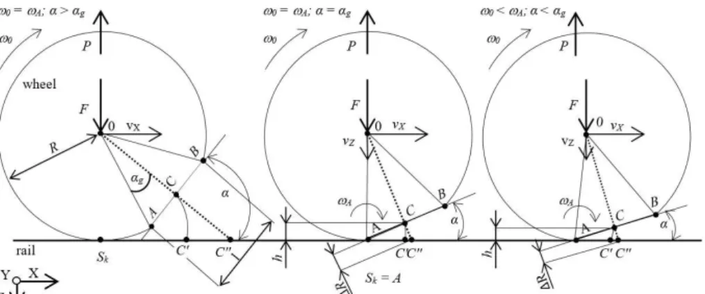
Flat spots are caused by absolute or temporary lock of the wheel axis as a result of incorrect breaking process, or decreased traction in the wheel-rail area (moisture, contamination). In such cases, locked wheels are propelled along the rail, grinding the rolling surface material. The ground material is often relocated on the rolling surface behind the flat spot, creating spalling. Wheel flats can cause similar types of dynamic loads as track irregularities or rail corrugation, and amplitudes of these dynamic loads can equal to 100% or more of the static load (Knothe & Stichel, 2017). Model of the phenomenon has been presented on Figure 2.
Figure 2: Model of wheel-flat: vx, vz–wheel linear velocity, ω0– wheel rotational velocity, F – total dynamic force of sprung and
unsprung elements per one wheel, R – radius of wheel, P – d'Alembert's reaction force between wheel and rail, l – defect length, Sk - temporary pivot point of the wheel, ω0–wheel torque, ωA–torque at contact point a, αg– angle describing the geometry of the flat
The observed results are - loss of noiselessness during movement (high levels of noise), as well as increased dynamic impact on the rail. The impact is significant and different to those resulting from roughness in constant contact with running surfaces of the wheel and rail. Total dynamic force of sprung and unsprung elements per one wheel (F) is sum of total load of vehicle per one wheel and dynamic force of suspension system. In showed schema, d’Alembert’s reaction force (P) equals in value to total dynamic force of sprung and unsprung elements per one wheel.
It means as in formula. If 𝛼 ∉ 〈0, 𝛼𝑔〉 then the wheel rotation centre 0 is above the temporary rotation point Sk
and only the rotational movement of the wheel is carried out. Then basic assumptions are presented as follows:
l=2R sin (αg) (1)
Should the wheel flat occur, the 𝛼 = 𝛼𝑔, the complex wheel motion starts around the temporary rotation point until 𝛼 decreases to zero. Then the basic equations are as follows:
ωA=ω0+ω(α) (2)
hg=2lsin(αg) (3)
The beginning of the wheel flat point A (Sk = A) is now the wheel rotation centre. At this moment the wheel flat
area hits the rail surface (points C i C') and the impact noise is generated. This complex wheel motion around the temporary rotation point A is consisted of uniform motion in the X direction and uniformly accelerated in the Z direction. The cause for the uniform motion in the X direction is the wheel rotational movement. Whereas the accelerated motion in the Z direction is caused by the fact that the geometric wheel centre is not above the temporary rotation point A. The impact velocity at the point C=C' can be calculated by equation (6):
vimp_c=vimp_rot+vimp_c_acc (4)
According to the principle of energy conservation:
ghg=vimp_c_acc 2
2 (5)
vimp_c_acc=√2gh (6)
The equation (8) can be described in the following form:
vimp_c=2lω0+√2g2lsin(αg) (7)
sin(αg)=2Rl (8)
vimp_c=2lω0+√gl 2
2R
(9)
vimp_c=l(ω20+√2Rg)(10)
Using the principle of conservation of momentum, it can be written as:
mzvimp_c-mzv'impc=∫t0t0+τF dt (11)
mzvimp_c=∫t0t0+τF dt (13)
The equation (12) is substituted and the final version presents as follow:
mz=(l(ω20+√2Rg))=∫tt00+τF dt (14)
From the equation (14) one can deduce that the impact force from the wheel-rail dynamic interaction depends of the wheel rotation velocity, the wheel diameter and wheel flat dimension. At the same time, the influence of mass loss associated with a wheel flat is neglected due to its slight mass value. Moreover, dynamic track phenomena are also dependent on the vehicle load degree, vehicle suspension type, vertical and horizontal track stiffness, rail supporting system, technical condition of the vehicle and track (T. Nowakowski & Tomaszewski, 2017; Stypu3a, 2001; D. Thompson, 2009).
Causes of flat spot occurrence are well known and described in numerous papers, e.g. in handbook (D. J. Thompson, 2009). In (Nielsen & Igeland, 1995) the influence of wheel flat in different examples is described. Authors show calculation of contact force between wheel and rail due to wheel flat in function of vehicle speed and explain vertical dynamic interaction between an imperfect wheel and a track. Similar work is presented in (Clark, 1979) where an investigation into the dynamic effects on track of railway wheel flats is shown.
In (Yang & Thompson, 2014) the railway impact noise caused by rail or wheel irregularities, such as flat spots, rail joints, switches and crossings, is described using the time domain wheel-rail interaction model with a detailed numerical non-Hertzian contact. In the article the impact vibration response and noise due to the wheel flat using the numerical model were predicted and, according to authors, it was found to be in good agreement with the measurements. The impact noise generation due to wheel passing over rail joints using TWIN software and the equivalent roughness input is described in (Wu & Thompson, 2003). Wheel flats problem is analysed in the similar paper (Wu & Thompson, 2002). It was found that the impact noise radiation is related to train speed, the geometry of irregularities and the static wheel load.
In (Jergéus et al., 1999), the full-scale railway wheel flat experiment was carried out. More than 200 wheel flats were formed under controlled conditions, involving various wheel loads, train speed and sliding duration. Also the friction coefficient between the wheel and the rail was indirectly measured. The wheel flats samples have been metallographically examined, as well as the distribution of martensite, which has been studied.
Another approach is the time-domain moving Green function of a railway track and its application to wheel-rail interactions via the Duhamel integral equation (Sheng, Xiao, & Zhang, 2016). The rail head indentation is described in the article which can also be a replacement of a wheel flat (flat spot). Also the time domain Green function method is used in (Pieringer, Kropp, & Nielsen, 2014; Pieringer, Kropp, & Thompson, 2011) where the wheel-rail impact noise is caused by wheel flat.
In (Kanoje Sharma, S.C., Harsha, S.P., 2014) authors tried to analyse the subsurface crack beneath a wheel flat using FEM simulation. In this study authors proposed different wheel material coefficients and modelled the mass-spring-damper system.
A sound signal is also available for detecting a wheel-flat (Komorski, Nowakowski, Szymanski, & Tomaszewski, 2018). The authors used Short Time Fourier Transform (STFT) alghoritm to extract diagnostic information about wheels from microphone localized near track.
Results of such defects are considered on three surfaces: technical, economic and social. The technical aspect relates to the influence of the defects on stability of the wheelset and the influence of the generated vibrations on the construction’s durability. The economical aspect considers all the costs associated with reprofiling the rolling surfaces as well as their shorter utility time. The social aspect considers complaints by the passengers and dwellers of buildings in close proximity to the tracks on increased vibrations and noise. Thus, considering these aspects, it is necessary to correctly recognize the technical state of the rolling surfaces by introducing flat spots detectors in a tram depot.
2 WHEEL-FLAT DETECTION SYSTEMS
The second used system is Revega, based on monitoring the pressure of wheels on rails at a distance of 3,6 m, with velocities no greater than 15km/h. Unfortunately, not all municipal transportation company in Poland are equipped with systems of detection of flat spots. In Poznan, only one of three tram depots is equipped with such a system.
There are many systems for detection of wheel-flat available. In (J. Brizuela, Fritsch, & Ibáñez, 2011) the ultrasound technique to railway wheel flat detection and measurement was proposed. The method uses Rayleigh wave ultrasonic pulses sent at regular intervals over measuring rail. The pulses travel on the rail surface and reach the wheel contact point, which produces an echo, which is analysed in case of wheel flats problem. The technique is robust against noise and the measurement is independent of the wheel wear degree and the wheel-flat roundness. However the system resolution decreases as the wheel speed increases, but relative errors are below 4% at maximum wheel speed of 3 m/s.
One year earlier, the same authors proposed the railway wheels flat detector system using Doppler effect (Jose Brizuela, Ibañez, Nevado, & Fritsch, 2010). In this case the wheel-rail contact is analysed by frequency and phase shifts. The method can be applied only at the low and constant train speed, between 10-15 km/h. Monochromatic surface waves are propagated by special rail and any difference between emitted and received frequencies will point out a wheel tread defects. Also wheel flat diagnostic tool was developed in (Belotti, Crenna, Michelini, & Rossi, 2006). Proposed method based on rail vibration measurements, the discrete wavelet transform and wavelet coefficients of the first’s 10 levels. In comparison to ultrasound and Doppler methods, it seems to be a better idea because of higher train pass-by speed, with top speed of the 100 km/h. However the proposed method shows only the bogie where is defected wheel and does not point out exactly wheel flat. A similar, new approach, although with use of machine learning was introduced in (Krummenacher et al., 2017).
Another wavelet approach for rail wheel flats detection is presented in (Jia & Dhanasekar, 2007). In this study vibration signal average techniques, wavelet local energy average concept and wavelet decomposition were proposed. Research results have been shown that the method it is a good idea for on-board wheel flat diagnostic system. However the tool is effective for wheel flats size monitoring smaller than the condemning limits (not bigger than 50 mm). Moreover the bogie vertical acceleration signature was used to investigation which means the system is good only for one type of train where is mounted.
Next approach (Li, Zuo, Lin, & Liu, 2017) is using axle box vibration signal processing. In this study, an algorithm for adaptive multiscale morphological filtering (AMMF) was developed for on-board wheel flat monitoring. All simulation and experimental research have shown good results however the device has to be mounted on each vehicle. The better idea for operators and maintainers is to use one system mounted in a track to diagnose all kind of vehicles.
The low-cost wheel flat detector (WFD) was presented in (Bracciali, Lionetti, & Pieralli, 1997). Proposed simple devices can be mounted in a track. The processing method is using signal filtering, Hilbert transformation, autocorrelation and power spectral density estimation which leading to a single figure that can be compared to reference data defined earlier. The WFD is working only with DTR device which is used to locate the passing wheels.
The time-frequency method for wheel and rail surface defect monitoring was proposed in (Liang et al., 2013). All research have been done on the roller test rig however proposed three time-frequency vibration techniques (Short Time Fourier Transform, Wigner Ville Transform and Wavelet Transform) were fulfilled the goal. Two accelerometers were installed on the wheel bearing seats and sets and also one was mounted on the bogie.
To sum up all wheel flats diagnostic systems presented above, it has to be point out the (Alemi, Corman, & Lodewijks, 2016) paper where all kind of condition monitoring approaches for detection of railway wheel defects are presented. This study is well-founded review of different techniques which includes ultrasonic, magnetic, acoustic, vibration, infrared cameras and strain gauges and other techniques or methods for wheel defects detection. The method of detecting wheel flats described in this paper is also unique and simplified, as shown further.
3 METHODOLOGY OF RESEARCH
Basic assumptions
Defects on rolling surfaces of wheels in the form of flat spots generate cyclical impulses in the wheel – rail area of contact. Thus, measurement points were located on the rail. These vibrations are characterized by low displacement amplitudes and high acceleration amplitudes (Chudzikiewicz, 2002). Therefore, acceleration was assumed as a basic physical quantity.
extraction of a signal envelope containing a low frequency modulation, which corresponds to cyclical impulses, indicating a flat spot on a wheel. The suggested method considers analysis of envelope in the time domain as well as the frequency domain.
Impulses events on rails coming from a flat spot are also characterized by low energy, when compared to the total energy in the vibration signal. The higher harmonics of repeating impulses will thus be amplified during resonance of the vibration-emitting structure, i.e. the rail. It is another argument for use of envelope analysis, which uses resonance vibrations carrying information about impulses (defects in the form of flat spots). Thus, analysis of signals from tram passes followed the analysis of rail structure dynamics.
In order to minimize financial expense, measurement points were located only on one rail (above the sleepers). The number of measurement points (Pm) was determined by considering the maximum circumference of the wheel
(cw,max) and distances between sleepers (ls), as in the formula (15).
Pm= int(cw, maxls ) | Pm∈ N (15)
Thusly determined measurement points designate the controlled length of the rail (Creal) upon which contact with
a flat spot is certain. The suggested method of wheel-flat detection assumes a divalent grading of technical state, considering the limit values of vibration acceleration as criteria for grading, statewise with a collection of states W:
W={w1,w2} (16)
where: w1– bad condition of tram, w2– good condition of tram.
Objects, localization and conditions of research
Research was conducted on a track of a tram depot S2 of MPK Poznañ. The track upon which measurements were realized was constructed from a rail 60R2 on Moll sleepers, which are located at a distance of 750 mm (ls). The greatest
expected circumference of a wheel in MPK Poznañ rail stock, assuming a nominal radius of 654 mm (r) is approx. 2054 mm (cw,max). Applying those values to the formula (15), denoting a necessity for 4 measurement points on the rail. The
real controlled distance was 2250 mm (Creal). Location of the measurement points has been shown on Figure 3.
Figure 3: A view of the measurement points location with a basic designations of dimensions and measurement realization: ù0–
Figure 4: Scheme of the test object – Moderus Beta MF 22 AC BD (tram).
Acquisition and archiving measurement's data was carried out using a multi-channel data acquisition module LAN-XI type 3050 (Brüel & Kjær). For registering of vibration signals piezoelectric transducer Brüel & Kjær type 4504 (PM1÷PM3) and type 4524 (PM4) was used. Research was conducted on Moderus Beta MF 22 AC BD trams, which has been shown on Figure 4 with its chosen technical parameters.
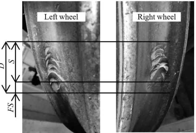
Research was conducted on trams realizing transportation processes for approx. a year. One tram was free of rolling surface defects, whereas other tram was observed to have defects in the form of flats spots on the last, 8th wheelset (Figure 5).
Figure 5:Wheel defect on wheel tread of tram #920 in the form of flat spots and spalling’: D – wheel defect on wheel tread, FS – flat spot, S – spalling (Tomasz Nowakowski et al., 2017).
Surface of the entire defect on the wheel tread of both wheels converted to coordinated of length and width of an approximated ellipse was equal to, correspondingly, 66 mm and 32 mm.
4 ANALYSIS OF RESEARCH RESULTS
During the research, 15 passes of a tram without defects on the wheels were registered, as well as 17 passes of a tram with a wheel-flat. In the beginning, cross-correlations between vibration signals were calculated.
Ka1,a2()=1T∫a1(t)a2(t+)dt (17)
where: a1,a2– analysed signals of vibration acceleration, t – time, ô – time delay.
Whereas in analysis the correlation was determined numerically, according to the formula (Cempel, 1978):
Ka1,a2(K∆)=NΔ1T∑Nn=0-1a1(nΔt)a2(nΔt+kΔt)Δt=Ka1,a2(k)=N1∑Nn=0-1a1(n)a2(n+k) (18)
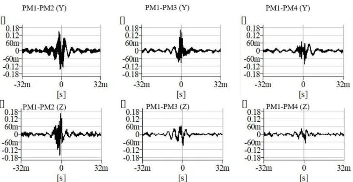
Results of mutual corelation analysis between signals PM1 and PM2, PM3 and PM4 has been depicted on Figure 6.
Figure 6: Charts of cross-correlation between vibration signals measured in all points of measurement.
From the charts above one may extrapolate, that the registered vibration signals had a degree of timeliness for all measurement points. The apex of cross–correlation function, falling close to the zero of time parameter (variation from 350,952 µs to 2,060 ms) is the evidence of this.
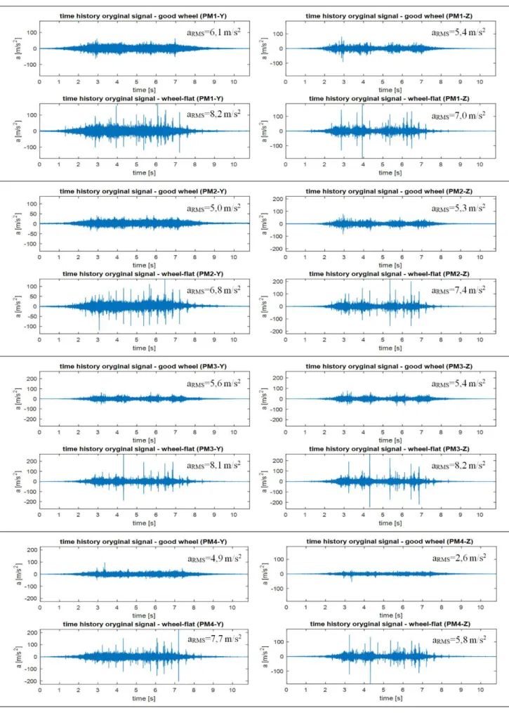
Analysis in the time domain
Transits of both trams differ significantly. The tram with wheel-flat is characterized by numerous spikes on every measurement point and in both directions of transit. It is caused by impulse reaction of the wheel and a flat spot on the rail. Maximum velocity of these spikes reached 280,1 m/s2 for direction Y and 263,7 m/s2 for direction Z in measurement point PM3. For comparison: The highest value of these measurements for a tram without damaged wheels was almost 70% lower for both directions.
The calculated point measurements of vibrations in the form of values of effective vibration acceleration (aRMS)
indicates a heightened influence during wheel-flat transits. Their values of aRMS were approximately more than 30% greater in both the Y and the Z direction. A slight divergence (below 7%) between the value of aRMS for a wheel-flat tram at point PM4-Z, and values for a faultless tram at points PM1-Z, PM3-Z should be noted. It indicates a necessity for flat spot detection with different methods, ones ensuring greater unambiguity. It also confirms a necessity for use of more than a single transducer.
In the next step singals from the time domain were transfered into the frequency domain, using the Fast Fourier Transform algorithm (FFT). The results have been collectively depicted on Figiure 8.
As indicated by specters on Figure 8, all frequency signals are contained below 9 kHz. However, despite the transit of two instances of a tram in various technical states, the characteristics of the specters are similar for both vehicles. The difference has to do with amplitude levels. The cause is a direct relation with the dynamic behavior of tracks, which in a readable manner changes it’s boundary values between measurement points. Brackets of resonance frequencies for measurement points have also been presented on the specters. Finally, all vibration signals were filtered by band– pass filter equivalent to the resonance frequency span. Filtered signals were subjected to demodulation in order to achieve signals’s envelope. Those signals could have contained low-frequency modulations correspondent to the cyclically appearing impulsive events resulting from the eventual flat spot on the wheel.
The method presented in this article allows for effective detection of wheel-flats in the domain of time or frequency. Later, Hilbert’s Transform (HT) has been applied for time signals a(t). In the following study, Hilbert’s
Transform of signals has been determined numerically according to the equation (21).
a
⃡(k)=∑Nn=−01hk−na(n) (19)
where:
hn=
{
2
Nsin2(0,5πn)ctg( πn
N )
Nϵf(n) f(n)=2n 2
N[1- cos(πn)ctg( πn
N )/cos( πn
N )]
Nϵf(n) f(n)=2n+1
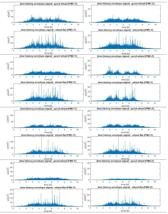
Envelopes of time signals for tram transit have been depicted on Figure 9. As seen on Figure 9 time signal envelope from the tram with wheel-flat is characterized by the appearance of the explicit peak of the amplitude higher than 35 m/s2, whereas time signal envelope from tram without defects shows no such feature. The conclusion from this analysis implies that monitoring of the amplitude of the acceleration of vibration in the time signal envelope may be a successive method of detection of flat spots. In this case, acceleration of vibration must be treated as the diagnostic parameter a(t)=S, which, after achieving the set limit value Sg would show the occurrence of the flat spots on
the wheel. In this case it is necessary to define the set limit value Sg of the observed diagnostic parameter S,
Figure 8: Signals in the frequency domain of both tested trams from all measurement points.
Figure 9: Envelopes of time signals for a tram with wheel-flat and a faultless tram.
Analysis in the frequency domain
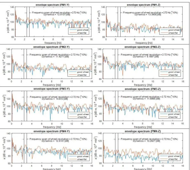
Figure 10: Spectrum from envelope vibration signals for trams.
In the case of the FFT specter from the signal envelope, a stark contrast between transits is observed in the values of amplitudes in frequency bands corresponding to rotational velocity of the wheels. Simultaneously a greater amplitude of a signal in the given boundaries indicated a wheel-flat tram. The dynamics of changes in direction Y equall approximately 12,8 dB, in direction Z approximately 10,4 dB. Thus, there exists a possibility of introducing an unambiguous cut-off point for the amplitude value in the examined band of frequencies for wheel-flat detection.
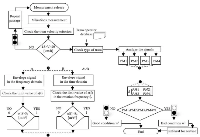
Finally, a universal algorithm for identifying the irregularities for the light rail vehicles was developed, presented on Figure 11. The signal of the start of the measurements can be made freely by the user, for example from the signal of the inductive sensor, which can detect the wheel set. When the velocity criteria will have been fulfilled, there comes the processing of the signals from all of the transducers, with the use of the envelope analysis. Every signal undergoes the analysis, depending on the chosen variant of the algorithm’s functionality in the time domain (variant A) or in the frequency domain (variant B). Independently from the variant, the extreme values individually established by the user of the system are checked on the base of numerous observations of the wheel’s defect, as the flat spots and the accompanying vibration’s signals. If, in whichever point of the measurement, the limit values will be exceeded, the technical state of the tram will be in a bad condition –w1. It is equivalent to referral the tram for the service, otherwise
Figure 11: The universal algorithm for detection of the flat spots on the tram wheels.
5 SUMMARY
The method presented in this research paper points out a large equivalence in the interpretation of the outcomes and the efficiency in detecting flat spots on the wheels, verified in the real-life exploitation. Experimentally, the connection between the flat spots on the rolling wheel presence and an ignition of vibration of the track was indicated.
It is possible to base the research on the results of signal analysis in the time domain, as well as in the frequency domain. In both cases, the actions are based on clear, numerical values in a convenient for operators, binary system of “bad/good wheel conditions”. The proposed system can be personalized for every tram depot. The final algorithm can be introduced as soon as the only condition, of using a sufficient number of transducers for the expected diameters of the operating rolling stock wheel diameter, is met. Moreover the described method can be used in a wider extent of pass-by velocities. Using the proposed method will successfully contribute to regular wheel surface monitoring. After introducing necessary corrections to rolling surfaces of wheels, the number of trams with heightened vibroacoustic activity will be reduced. It is especially crucial for rolling stock in heavily urbanized environments.
6 ACKNOWLEDGEMENTS
All presented work is partly funded by Statutory Activities fund of the Institute of Combustion Engines and Transport, PUT (PL) 5/52/DSPB/0259. Thanks to the Municipal Communication Company in Poznañ for the possibility of carrying out measurements at the Franowo depot.
References
Alemi, Corman, F., & Lodewijks, G. (2016). Review on condition monitoring approaches for the detection of railway wheel
defects. Proceedings of the Institution of Mechanical Engineers, Part F: Journal of Rail and Rapid Transit, 0(0), 1–21.
https://doi.org/10.1177/0954409716656218
Belotti, V., Crenna, F., Michelini, R. C., & Rossi, G. B. (2006). Wheel-flat diagnostic tool via wavelet transform. Mechanical
Bracciali, A., Lionetti, G., & Pieralli, M. (1997). Effective wheel flats detection through a simple device. World Congress on Railway Research WCRR, 97, 513–521.
Brizuela, J., Fritsch, C., & Ibáñez, A. (2011). Railway wheel-flat detection and measurement by ultrasound. Transportation
Research Part C: Emerging Technologies,19(6), 975–984. https://doi.org/10.1016/j.trc.2011.04.004
Brizuela, J., Ibañez, A., Nevado, P., & Fritsch, C. (2010). Railway wheels flat detector using doppler effect. Physics Procedia,
3(1), 811–817. https://doi.org/10.1016/j.phpro.2010.01.104
Cempel, C. (1978). Wibroakustyka stosowana (ang. Applied vibroacoustics). Warszawa-Poznañ: PWN (Scientific Polish
Publishing House).
Chudzikiewicz, A. (2002). Elementy diagnostyki pojazdów szynowych (ang. Diagnostics of rail vehicles). Warszawa: Warsaw
Univeristy of Technology.
Clark, R. A. (1979). An investigation into the dynamic effects on the track of wheelflats on railway vehicles. J. of Mech. Eng.
Science. https://doi.org/10.1243/JMES_JOUR_1979_021_046_02
Jergéus, J., Odenmarck, C., Lundén, R., Sotkovszki, P., Karlsson, B., & Gullers, P. (1999). Full-scale railway wheel flat
experiments. In Proceedings of the Institution of Mechanical Engineers, Part F: Journal of Rail and Rapid Transit (p. vol. 213: 1).
https://doi.org/10.1243/0954409991530985
Jia, S., & Dhanasekar, M. (2007). Detection of Rail Wheel Flats using Wavelet Approaches. Structural Health Monitoring: An
International Journal. https://doi.org/10.1177/1475921706072066
Kanoje Sharma, S.C., Harsha, S.P., N. K. (2014). EPFM Analysis of Subsurface Crack Beneath a Wheel Flat using Dynamic
Condition. 3rd International Conference on Materials Processing and Characterization (ICMPC 2014), 6(Icmpc), 43–60.
https://doi.org/10.1016/j.mspro.2014.07.007
Knothe, K., & Stichel, S. (2017). Rail Vehicle Dynamics. Cham: Springer International Publishing.
https://doi.org/10.1007/978-3-319-45376-7
Komorski, P., Nowakowski, T., Szymanski, G. M., & Tomaszewski, F. (2018). Application of Time-Frequency Analysis of Acoustic
Signal to Detecting Flat Places on the Rolling Surface of a Tram Wheel. Springer International Publishing. https://doi.org/10.1007/978-3-319-96601-4
Krummenacher, G., Ong, C. S., Koller, S., Kobayashi, S., Buhmann, J. M., & Member, S. (2017). Wheel Defect Detection With
Machine Learning, 1–12.
Li, Y., Zuo, M. J., Lin, J., & Liu, J. (2017). Fault detection method for railway wheel flat using an adaptive multiscale
morphological filter. Mechanical Systems and Signal Processing,84, 642–658. https://doi.org/10.1016/j.ymssp.2016.07.009
Liang, B., Iwnicki, S., Feng, G., Ball, A., Tran, V. T., & Cattley, R. (2013). Railway wheel flat and rail surface defect detection by
time-frequency analysis. Chemical Engineering Transactions,33, 745–750. https://doi.org/10.3303/CET1333125
Madejski, J. (2006). Automatic detection of flats on the rolling stock wheels. Journal of Achievements in Materials and …, 16(1),
160–163. Retrieved from http://www.w.journalamme.org/papers_cams05/1204.pdf
Nielsen, J. C. O., & Igeland, A. (1995). Vertical Dynamic Interaction Between Train and Track Influence of Wheel and Track
Imperfections. Journal of Sound and Vibration,187(5), 825–839. https://doi.org/10.1006/jsvi.1995.0566
Nowakowski, T., Komorski, P., & Szymañski, G. M. (2017). Application of Hilbert transform in detection flat spots on tram
wheels. In Mathematical and Numerical Aspects of Dynamical System Analysis(p. 2017). £ódŸ.
Nowakowski, T., & Tomaszewski, F. (2017). Analysis of dynamic tram-track interactions based on paraseismic vibration. In 24th
International Congress on Sound and Vibration, ICSV 2017.
Piec, P. (1999). Zjawiska kontaktowe w elementach pojazdów szynowych (ang. Contact phenomena in rail vehicle
components). Kraków: Instytut Technologii Eksploatacji.
Pieringer, A., Kropp, W., & Nielsen, J. C. O. (2014). The influence of contact modelling on simulated wheel/rail interaction due
to wheel flats. Wear,314(1–2), 273–281. https://doi.org/10.1016/J.WEAR.2013.12.005
Pieringer, A., Kropp, W., & Thompson, D. J. (2011). Investigation of the dynamic contact filter effect in vertical wheel/rail
interaction using a 2D and a 3D non-Hertzian contact model. Wear,271(1–2), 328–338.
Sheng, X., Xiao, X., & Zhang, S. (2016). The time domain moving Green function of a railway track and its application to wheel–
rail interactions. Journal of Sound and Vibration,377, 133–154. https://doi.org/10.1016/j.jsv.2016.05.011
Stypu3a, K. (2001). In¿ynieria l1dowa no. 72. Krakow: Publishing house of the Cracow University of Technology.
Thompson, D. (2009). Railway noise and vibration: mechanism, modeling and means of control. Elsevier.
Thompson, D. J. (2009). Railway Noise and Vibration. Mechanisms, Modelling and Means of Control. Journal of Chemical
Information and Modeling,53(9), 519. https://doi.org/10.1017/CBO9781107415324.004
Wu, T. X., & Thompson, D. J. (2002). A hybrid model for the noise generation due to railway wheel flats. Journal of Sound and
Vibration,251(1), 115–139. https://doi.org/10.1006/jsvi.2001.3980
Wu, T. X., & Thompson, D. J. (2003). On the impact noise generation due to a wheel passing over rail joints. Journal of Sound
and Vibration,267(3), 485–496. https://doi.org/10.1016/S0022-460X(03)00709-0