U
NIVERSIDADE DE
L
ISBOA
Faculdade de Ciˆencias
Departamento de Inform´atica
DEVELOPMENT AND UPDATE OF
AEROSPACE APPLICATIONS IN
PARTITIONED ARCHITECTURES
Joaquim Lu´ıs Santo Rodrigues Cleto Rosa
MESTRADO EM ENGENHARIA INFORM ´
ATICA
U
NIVERSIDADE DE
L
ISBOA
Faculdade de Ciˆencias
Departamento de Inform´atica
DEVELOPMENT AND UPDATE OF
AEROSPACE APPLICATIONS IN
PARTITIONED ARCHITECTURES
Joaquim Lu´ıs Santo Rodrigues Cleto Rosa
DISSERTAC
¸ ˜
AO
Trabalho orientado pelo Prof. Doutor Jos´e Manuel de Sousa de Matos Rufino
MESTRADO EM ENGENHARIA INFORM ´
ATICA
This work was partially funded by:
ESA/ITI - European Space Agency Innovation Triangular Initiative (through ESTEC Contract 21217/07/NL/CB - ProjectAIR-II)
Acknowledgements
This thesis represents for me the conclusion of five years of study with results which I could not achieve without the help and support of several people. I ex-press herein my gratitude to all of them.
Firstly, I would like to thank my advisor, Prof. Jos´e Rufino, for his crucial help during the development of this thesis. His remarks and suggestions have always contributed to the increase of my knowledge and to develop further my work. His dedication and support while I was writing this thesis and related articles was truly important. His motivation and enthusiasm forced me to keep working even in the hardest moments, and to always choose my own way to achieve the proposed goals.
Secondly I would like to thank Jo˜ao Craveiro, Jeferson Souza, and Ricardo Pinto, for all the valuable insights given during my research work and academic route. Their availability, good advices, and friendship were extremely important for me.
Thirdly, I would like to thank Navigators and all of the LaSIGE fellows for the interesting and constructive discussions where I learnt a lot.
I also would like to thank all my colleagues from Informatics Engineering, especially those from 2006/2007 class, with whom I shared the same passion.
Moreover, I am very grateful to all my professors and people from the DI, for being so warm and helpful, and for having taught me so many interesting things. I thank FCUL for being my school and my home for the last five years.
I thank all my friends from FCUL, from whom I learnt interesting topics be-yond Informatics, I thank new friends, for sharing their diversified life experi-ences, and to old friends, for always being there when I needed.
Lastly but not least, I would like to thank my family for all the support and opportunities given. Thank you for believing in me.
Lisboa, April 2011
Abstract
To face the challenges and requirements imposed by future space missions, the aerospace industry has been following the trend of adopting innovative and ad-vanced computing system architectures fulfilling strict requisites of size, weight and power consumption (SWaP) thus decreasing the mission overall cost and en-suring the safety and timeliness of the system.
The AIR (ARINC 653 in Space Real-Time Operating System) architecture has been defined dependent on the interest of the aerospace industry, especially the European Space Agency (ESA). AIR provides a partitioned environment for the development and execution of aerospace applications, based on the idea of time and space partitioning (TSP), aiming the preservation of the application require-ments, timing and safety.
During a space mission, the occurrence of unexpected events or the change of the mission plans introduces new constraints to the mission. Therefore, it is paramount to have the possibility to host new applications in spacecraft onboard computer platform, or modify the existing ones in execution time, thus fulfilling new requirements or enhancing spacecraft functions.
The work described on this thesis introduces in the AIR architecture the sup-port for the inclusion of new features to the mission plan during the system op-eration. These new features may be composed of modified software components or the corresponding timing requirements. The improvement of the AIR architec-ture with the ability to perform software updates requires a suitable development environment and tools. Therefore, the methodology for software development in AIR-based systems, regarding the build and integration process, is reexamined.
Keywords:Aerospace systems and applications, software update, time and space partitioning (TSP), adaptability and reconfigurability, real-time embedded systems
Resumo
Para enfrentar os desafios e requisitos impostos por miss ˜oes espaciais futuras, a ind ´ustria aeroespacial tem vindo a seguir uma tendˆencia para adoptar arquitec-turas computacionais inovadoras e avanc¸adas, cumprindo requisitos estritos de tamanho, peso e consumo energ´etico (SWaP) e assim diminuir o custo total da miss˜ao assegurando a seguranc¸a na operac¸˜ao e a pontualidade do sistema.
A arquitectura AIR (ARINC 653 in Space Real-Time Operating System), de-senvolvida para responder ao interesse da ind ´ustria aeroespacial, particularmente da Agˆencia Espacial Europeia (ESA), fornece um ambiente compartimentado para o desenvolvimento e execuc¸˜ao de aplicac¸ ˜oes aeroespaciais, seguindo a noc¸˜ao de compartimentac¸˜ao temporal e espacial, preservando os requisitos temporais das aplicac¸ ˜oes e a seguranc¸a na operac¸˜ao.
Durante uma miss˜ao espacial, a ocorrˆencia de eventos inesperados ou alte-rac¸ ˜oes aos planos da miss˜ao introduz novas restric¸ ˜oes. Assim, ´e de grande im-portˆancia ter a possibilidade de alojar novas aplicac¸ ˜oes na plataforma computa-cional de ve´ıculos espaciais ou modificar aplicac¸ ˜oes j´a existentes em tempo de execuc¸˜ao e, deste modo, cumprir os novos requisitos ou melhorar as func¸ ˜oes do ve´ıculo espacial.
O presente trabalho introduz na arquitectura AIR o suporte `a inclus˜ao e actua-lizac¸˜ao de novas funcionalidades ao plano de miss˜ao durante o funcionamento do sistema. Estas funcionalidades podem ser formadas por componentes de soft-ware modificados ou pelos requisitos temporais correspondentes. O melhora-mento da arquitectura AIR com a possibilidade de realizar actualizac¸ ˜oes de soft-ware requer um ambiente e ferramentas de desenvolvimento adequados. Neste sentido, a metodologia para o desenvolvimento de software em sistemas basea-dos na arquitectura AIR ´e revisitada.
Palavras-chave:Sistemas e aplicac¸ ˜oes aeroespaciais, actualizac¸˜ao de software, compartimentac¸˜ao temporal e espacial, adaptabilidade e reconfigurabilidade, tempo-real
Resumo alargado
1Miss ˜oes espaciais futuras precisam de uma nova gerac¸˜ao de ve´ıculos espaciais. Esta necessidade tem suscitado o interesse de agˆencias espaciais e parceiros in-dustriais na definic¸˜ao e desenho dos pilares de construc¸˜ao fundamentais para no-vas plataformas computacionais a bordo de ve´ıculos espaciais, onde as necessida-des estritas de confiabilidade, pontualidade, seguranc¸a na operac¸˜ao e seguranc¸a da informac¸˜ao s˜ao combinadas com um requisito global para reduzir o tamanho, peso e consumo energ´etico da infraestrutura computacional.
A definic¸˜ao de arquitecturas compartimentadas que implementem a conten-c¸˜ao l ´ogica de aplicac¸ ˜oes em dom´ınios de criticalidade, designados por partic¸ ˜oes, permite alojar diferentes partic¸ ˜oes na mesma infraestrutura computacional e pos-sibilita o cumprimento dos requisitos referidos. A noc¸˜ao de compartimentac¸˜ao temporal e espacial assegura que as actividades de uma partic¸˜ao n˜ao afectam a pontualidade das actividades em execuc¸˜ao noutras partic¸ ˜oes e impede as aplica-c¸ ˜oes de acederem ao espaaplica-c¸o de endereaplica-c¸amento de cada uma das outras.
No contexto das aplicac¸ ˜oes aeroespaciais suportadas por uma arquitectura compartimentada, as diversas func¸ ˜oes de um ve´ıculo espacial, tais como o subsis-tema de Controlo Orbital e de Orientac¸˜ao, ou o subsissubsis-tema de Telemetria, Rastreio e Comando, partilham os mesmos recursos computacionais e ao mesmo tempo mantˆem a sua independˆencia no que diz respeito `a contenc¸˜ao de eventuais faltas e `a validac¸˜ao e verificac¸˜ao de software, ficando alojadas em partic¸ ˜oes distintas. No dom´ınio temporal, as diferentes partic¸ ˜oes s˜ao escalonadas de acordo com ta-belas de escalonamento fixas e c´ıclicas.
Para a escrita, construc¸˜ao, depurac¸˜ao, e manutenc¸˜ao das aplicac¸ ˜oes em arqui-tecturas compartimentadas ´e necess´ario ultrapassar algumas limitac¸ ˜oes pr ´oprias das ferramentas cl´assicas de gerac¸˜ao de software, que n˜ao foram desenhadas para o desenvolvimento deste g´enero de aplicac¸ ˜oes. Identificadas as limitac¸ ˜oes, um dos desafios ´e encontrar soluc¸ ˜oes e adaptar as ferramentas j´a existentes de forma a conseguir ter um ambiente de desenvolvimento de aplicac¸ ˜oes em arquitecturas compartimentadas funcional. Este ambiente de desenvolvimento deve permitir realizar a construc¸˜ao das aplicac¸ ˜oes de cada partic¸˜ao de forma independente e a sua posterior integrac¸˜ao, tendo em conta que num cen´ario t´ıpico estas s˜ao forne-cidas por diferentes equipas de desenvolvimento ou fornecedores de software.
A arquitectura AIR (ARINC 653 In Space Real-Time Operating System), de-senvolvida para responder aos interesses da ind ´ustria aeroespacial, particular-mente da Agˆencia Espacial Europeia (ESA), emerge como uma arquitectura com-partimentada para o desenvolvimento e execuc¸˜ao de aplicac¸ ˜oes aeroespaciais aplicando os conceitos de compartimentac¸˜ao temporal e espacial, contemplando os requisitos de tempo-real e seguranc¸a na operac¸˜ao. A arquitectura AIR per-mite a execuc¸˜ao de sistemas operativos, tanto de tempo-real como gen´ericos, em partic¸ ˜oes independentes respeitando a norma ARINC 653, assegura inde-pendˆencia da infraestrutura de processamento, e possibilita a verificac¸˜ao e va-lidac¸˜ao independente dos componentes de software. O processo de verificac¸˜ao e validac¸˜ao assegura que o software cumpre com as suas especificac¸ ˜oes e responde aos requisitos definidos para a miss˜ao.
Durante o decorrer de uma miss˜ao espacial, podem surgir situac¸ ˜oes nas quais pode ser necess´ario, ´util ou mesmo primordial modificar func¸ ˜oes j´a existentes ou introduzir novas funcionalidades no computador de bordo de uma nave espacial para lidar com eventos inesperados. Para al´em disso, por exemplo na presenc¸a de falhas de alguns componentes, pode revelar-se ´util proceder a alterac¸ ˜oes no plano de miss˜ao, tais como reconfigurar o escalonamento das aplicac¸ ˜oes em execuc¸˜ao ou efectuar modificac¸ ˜oes nas aplicac¸ ˜oes existentes. Exemplos reais evidenciam a utilidade da realizac¸˜ao de actualizac¸ ˜oes de software sem implicar a ocorrˆencia de quebras de servic¸o ou paragens do sistema. Neste sentido, ´e preciso explorar abordagens que consigam concretizar as actualizac¸ ˜oes de componentes de soft-ware das partic¸ ˜oes em arquitecturas compartimentadas e ao mesmo tempo ga-rantir que todos os requisitos dos sistemas cr´ıticos s˜ao cumpridos. ´E por isso muito importante que, para al´em da existˆencia de uma plataforma adequada para o desenvolvimento e integrac¸˜ao de aplicac¸ ˜oes, seja poss´ıvel concretizar a transferˆencia de actualizac¸ ˜oes das aplicac¸ ˜oes durante o normal funcionamento do sistema, sem que isso implique colocar em causa a seguranc¸a na operac¸˜ao e a pontualidade das aplicac¸ ˜oes em execuc¸˜ao. Assim, o desenvolvimento de uma metodologia para actualizac¸˜ao de componentes de software deve permitir que as alterac¸ ˜oes ao software possam ser aplicadas continuando a cumprir os requisitos temporais definidos para as restantes aplicac¸ ˜oes e a seguranc¸a no funcionamento. Para efectuar actualizac¸ ˜oes de software assegurando os requisitos descritos, ´e necess´ario verificar quais as dependˆencias que podem existir entre os diversos componentes do sistema, determinar quais os instantes em que as actualizac¸ ˜oes podem ser efectuadas, e concretizar, efectivamente, a substituic¸˜ao dos compo-nentes. Isto requer um ambiente e ferramentas de desenvolvimento adequados, incluindo o suporte para a verificac¸˜ao e validac¸˜ao dos componentes modificados, durante o processo de construc¸˜ao e integrac¸˜ao de aplicac¸ ˜oes.
Esta tese aborda soluc¸ ˜oes que, suportadas por m´etodos e ferramentas de de-senvolvimento apropriadas, permitem proceder `a actualizac¸˜ao de aplicac¸ ˜oes em partic¸ ˜oes espec´ıficas e de tabelas de escalonamento de partic¸ ˜oes, tendo em conta os conceitos de separac¸˜ao espacial impostos pela norma ARINC 653, no que diz respeito `a existˆencia de mecanismos de protecc¸˜ao do acesso ao espac¸o de enderec¸amento das partic¸ ˜oes, e os requisitos temporais das mesmas.
Durante o decurso do trabalho desta dissertac¸˜ao foi desenvolvida uma meto-dologia para realizar actualizac¸ ˜oes para arquitecturas compartimentadas aplica-das aos sistemas aeroespaciais. Esta metodologia serviu de base para a concreti-zac¸˜ao de duas funcionalidades essenciais. A primeira diz respeito `a actualiconcreti-zac¸˜ao de tabelas de escalonamento de partic¸ ˜oes, de forma a contribuir para a reconfigu-rabilidade do sistema, tornando dispon´ıvel novas tabelas de escalonamento de partic¸ ˜oes constru´ıdas a partir de novos planos de miss˜ao. A segunda funciona-lidade desenvolvida permite realizar a actualizac¸˜ao de componentes de software das partic¸ ˜oes, permitindo assim adaptar as func¸ ˜oes do ve´ıculo espacial durante a miss˜ao. Foi concretizado um prot ´otipo para a demonstrac¸˜ao das funcionali-dades de actualizac¸˜ao descritas no contexto da arquitectura AIR, acrescentando assim um novo mecanismo para atingir adaptabilidade `a arquitectura. O melho-ramento da arquitectura AIR com a possibilidade de realizar actualizac¸ ˜oes intro-duziu alterac¸ ˜oes no ambiente e ferramentas de desenvolvimento. Neste sentido, o processo de desenvolvimento de software em sistemas compartimentados foi revisitado, com vista `a definic¸˜ao de um processo de construc¸˜ao e integrac¸˜ao de aplicac¸ ˜oes que possibilite a concretizac¸˜ao flex´ıvel de actualizac¸ ˜oes de partic¸ ˜oes e respectivos requisitos temporais.
O trabalho descrito nesta tese consistiu na an´alise dos problemas em aberto relacionados com a actualizac¸˜ao de componentes de software e tabelas de esca-lonamento de partic¸ ˜oes, e no desenho e construc¸˜ao de soluc¸ ˜oes que permitem realizar actualizac¸ ˜oes durante o funcionamento do sistema. As soluc¸ ˜oes aborda-das obedecem aos conceitos da segregac¸˜ao temporal e espacial aborda-das arquitecturas compartimentadas presentes nos sistemas aeroespaciais.
Futuros desenvolvimentos dizem respeito `a actualizac¸˜ao de partic¸ ˜oes dina-micamente, i. e., modificar os componentes de software sem que a partic¸˜ao cor-respondente tenha de ser parada. Isto pressup ˜oe o estudo e desenvolvimento de servic¸os de gest˜ao dinˆamica de mem ´oria, e a sua adaptac¸˜ao `as arquitecturas compartimentadas. A actualizac¸˜ao de parˆametros de configuac¸˜ao e controlo do sistema, o estudo e aplicac¸˜ao de metodologias de actualizac¸˜ao dinˆamica de siste-mas operativos em arquitecturas compartimentadas est˜ao tamb´em previstos.
1Em cumprimentos do disposto no Artigo 27.o, n.o3, da Deliberac¸˜ao n.o1506/2006
Contents
Acknowledgements v
Abstract ix
Resumo xi
Resumo alargado xiii
List of Figures xxi
List of Tables xxiii
List of Algorithms xxv
Abbreviations xxix
1 Introduction 1
1.1 Motivation . . . 2
1.2 Goals and contributions . . . 3
1.3 Institutional context . . . 4
1.4 Publications . . . 4
1.5 Document outline . . . 5
2 Background 7 2.1 Spacecraft systems overview . . . 7
2.2 Onboard computers. . . 9
2.3 Common faults in spacecraft. . . 14
2.4 Verification and validation process . . . 17
2.5 Software update . . . 19
2.6 Summary . . . 20
3 AIR Technology design 21 3.1 System architecture . . . 21
3.1.2 AIR Health Monitor . . . 22
3.1.3 Interpartition communication . . . 23
3.2 Schedulability . . . 23
3.3 Composability . . . 24
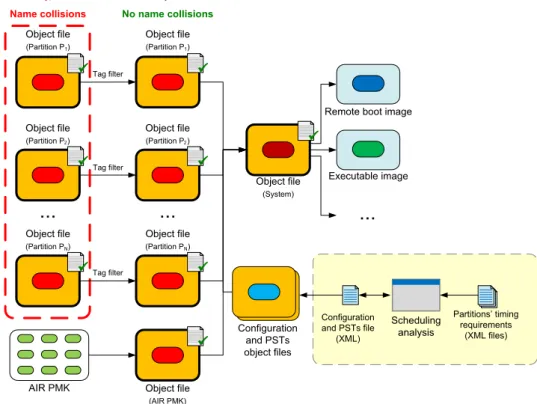
3.4 Build and integration process . . . 24
3.4.1 Partition build process . . . 25
3.4.2 System integration . . . 26
3.4.3 Impact on the software development lifecycle . . . 27
3.5 Summary . . . 28
4 Problem definition 29 4.1 Computational model . . . 29
4.1.1 Defining requirements and components . . . 29
4.1.2 Integration on spacecraft onboard platform . . . 30
4.2 Open challenges in onboard software update . . . 31
4.2.1 Problem definition . . . 31
4.2.2 Proposed methodology . . . 32
4.3 Summary . . . 33
5 Updating partition schedules 35 5.1 Scheduling partitions . . . 35
5.2 Safe update of partition schedules . . . 36
5.2.1 The XAPEX PSTUPDATE service . . . 36
5.2.2 Onboard update of PSTs . . . 37
5.2.3 Achieving reconfigurability . . . 39
5.3 PSTs update algorithm analysis . . . 39
5.3.1 Code complexity . . . 39
5.3.2 Computational complexity . . . 40
5.4 Proof-of-concept prototype and evaluation . . . 40
5.4.1 Prototyping . . . 40
5.4.2 Evaluation . . . 41
5.5 Summary . . . 44
6 Updating partition software components 47 6.1 Safe update of partitions . . . 47
6.1.1 The XAPEX PUPDATE service . . . 47
6.1.2 Onboard update of partitions in the idle mode . . . 48
6.1.3 Achieving adaptability . . . 51
6.1.4 Impact of the update methodology . . . 51
6.2 Proof-of-concept prototype and evaluation . . . 52 xviii
6.2.1 Prototyping . . . 52 6.2.2 Evaluation . . . 53 6.3 Summary . . . 55 7 Conclusion 57 7.1 Future work . . . 57 Bibliography 65
List of Figures
2.1 Structural organization of spacecraft subsystems . . . 8
2.2 Onboard processor evolution . . . 12
2.3 Simplified onboard computational infrastructure . . . 13
2.4 Subsystems affected during a mission . . . 15
2.5 Time to failure after launch . . . 16
2.6 Spacecraft failures during 1981–2000 . . . 17
3.1 AIR system architecture and integration of partition operating sys-tems . . . 22
3.2 Two-level mode-based partition scheduling . . . 23
3.3 Software building by partition application developers . . . 25
3.4 System integration . . . 26
3.5 Impact on the software development lifecycle. . . 27
4.1 Spacecraft time- and space-partitioned computing platform . . . . 30
5.1 Update of a set of PSTs . . . 37
5.2 Prototype implementation demonstration, featuring the VITRAL text-mode windows manager for RTEMS . . . 41
5.3 Partition scheduling tables used in test scenarios . . . 43
6.1 Impact of the update methodology on the software development lifecycle . . . 52
6.2 Prototype for the update of partitions, featuring the VITRAL text-mode windows manager for RTEMS . . . 53
6.3 Demonstration: activation of the partitions update operation . . . . 53
6.4 Demonstration: original partition has stopped its execution. . . 54
6.5 Demonstration: the updated partition has replaced the original one and was initialized . . . 54
List of Tables
2.1 CPUs used in spacecraft . . . 11
5.1 Logical SLOC and cyclomatic complexity (CC) for the XAPEX PST-UPDATE primitive and the AIR Partition Scheduler . . . 40
5.2 Partition scheduling tables used in test scenarios (for the prototype implementation demonstration) . . . 42
6.1 XAPEX memory management services foreseen . . . 48
List of Algorithms
1 APEX SWITCH SCHEDULE primitive . . . 35
2 AIR Partition Scheduler (mode-based schedules) . . . 36
3 XAPEX PSTUPDATE primitive . . . 37
4 XAPEX PUPDATE primitive . . . 48
5 AIR PMK Time Manager (original) . . . 50
Abbreviations
AIR ARINC 653 in Space RTOS
AOCS Attitude and Orbit Control Subsystem
APEX In ARINC 653 and AIR technology: Appli-cation Executive
ARINC Aeronautical Radio, INCorporated
BOL Beginning-of-life
CAN Controller Area Network
CC Cyclomatic Complexity
COTS Commercial Off-The-Shelf
CPU Central Processing Unit
DRAM Dynamic Random-Access Memory
E2PROM Electrically Erasable Programmable Read-Only Memory
EOL End-of-life
EPROM Erasable Programmable Read-Only Mem-ory
EPS Electrical Power Subsystem
ESA European Space Agency
FDIR Failure Detection, Isolation and Recovery
GNU GNU’s Not UNIX
HM In AIR technology: Health Monitor
I/O Input/Output
IEC International Electrotechnical Commission
IMA Integrated Modular Avionics
IMADE Integrated Modular Avionics Development Environment
ISS International Space Station
LEO Low Earth Orbit
MCC Mission Control Center
MECH Structure and Mechanism
MiB Mebibyte
MIPS Million Instructions Per Second
MISRA Motor Industry Software Reliability Associ-ation
MTF Major Time Frame
NASA National Aeronautics and Space Adminis-tration
OBC Onboard Computer
OBDH Onboard Data Handling
OI Orbit Insertion
OO On-orbit
OOS On-orbit Servicing
OS Operating System
PAL In AIR technology: POS Adaptation Layer
PC Personal Computer
PMK In AIR technology: Partition Management
Kernel
POS In AIR technology: Partition Operating Sys-tem
POSIX Portable Operating System Interface (for Unix)
PST Partition Scheduling Table
RAM Random-Access Memory
RF Radio Frequency
RISC Reduced Instruction Set Computing
ROM Read-Only Memory
RTEMS Real-Time Executive for Multiprocessor Sys-tems
RTOS Real-Time Operating System
SDRAM Synchronous Dynamic Random-Access Memory
SLOC Source Lines of Source Code
SPARC Scalable Processor Architecture
SRAM Static Random-Access Memory
SWaP Size, Weight and Power consumption xxviii
Abbreviations xxix
TCS Thermal Control Subsystem
TSP Time and Space Partitioning
TTC Telemetry, Tracking and Command
V & V Verification and Validation
WCET Worst-Case Execution Time
Chapter 1
Introduction
Future space missions call for a new generation of space vehicles. This need has led to the interest of space agencies and industrial partners in defining the build-ing blocks for new onboard computational platforms, where strict requirements of reliability, timeliness, safety and security are combined with a global requisite to decrease the size, weight and power consumption (SWaP) of the computational infrastructure.
The definition of partitioned architectures implementing the logical contention of applications in criticality domains, named partitions, allows to host different partitions in the same computational infrastructure and meet the enumerated re-quirements [1]. The notion of time and space partitioning (TSP) ensures that the execution of applications in one partition does not affect other partitions’ timing requisites and that separated addressing spaces are assigned to different parti-tions [2].
The design of the AIR (ARINC 653 in Space Real-Time Operating System) Technology has been prompted by the interest of the space industry partners, es-pecially the European Space Agency (ESA), in applying the TSP concepts to the aerospace domain [3, 4]. The AIR architecture allows the execution of both real-time and generic operating systems in distinct partitions, ensures independence from the processing infrastructure, and enables independent development, vali-dation and verification (V & V) of software components.
The computational infrastructure of a typical spacecraft hosts several subsys-tems, consisting of avionics functions, such as Attitude and Orbit Control Sub-system (AOCS), Onboard Data Handling (OBDH) and Telemetry, Tracking and Command (TTC), and payload, which closely interact with each other. In TSP sys-tems, the several functions share the same computational resources being hosted in different partitions, and supported by embedded systems.
The writing, build, debug and maintenance of applications in partitioned ar-chitectures requires overcoming some limitations imposed by the standard
devel-2 CHAPTER 1. INTRODUCTION opment tools, that were not designed to the development of such applications. It is necessary to adapt the existing tools in order to have an environment suitable to develop applications for partitioned architectures.
Furthermore, due to unexpected events or the change of environmental condi-tions, it may be necessary to improve the functions hosted in a spacecraft or even to add new ones, during a mission. This way, the onboard computing systems should be able to handle the reconfiguration and update of spacecraft functions without compromising the timeliness and the safety of the system.
This thesis describes a methodology for reconfigure and update system com-ponents and applications for time- and space-partitioned architectures, applied to aerospace systems, motivated by the need to adapt system behaviour to chang-ing conditions or unexpected events durchang-ing the system operation. The proof-of-concept prototype will be implemented within the scope of the AIR architecture. This involves improving the AIR architecture with the support for the remote modification of system’s parameters and the update of software onboard compo-nents.
1.1
Motivation
Throughout time, space exploration experience has demonstrated that recovery from many severe failures can be achieved through the update of software com-ponents [5]. The need for in-flight programmability has been identified by space agencies [6]. The incentive to build a system that supports the system reconfigu-ration, or even the modification of software components, comes from several inci-dents in the scope of aerospace missions, almost always related to failure events. The software upgradeability is a crucial property to spacecraft survival in long-term missions [7].
Mars Pathfinder success history
During the course of a mission, there may appear situations on which it could be necessary, useful and even primordial to change the actual system configuration. An anthology example is the case of the NASA’s Mars Pathfinder mission [8]. The rover Pathfinder, after landing on Mars surface and start collecting mete-orological data, began suffering of system restarts constantly. The failure in the system was identified has a classic priority inversion problem. The team working in Mars Pathfinder mission identified the reason of the system restarts through event log analysis and debug capabilities that fortunately were enabled. Then, to solve the problem, it was built a program to change the value of the global vari-ables that were causing the malfunction. The program was uploaded to the rover
1.2. Goals and contributions 3
and executed, turning the system back to its normal execution state.
Without the ability to debug and modify system parameters during its exe-cution, Mars Pathfinder mission could have failed because the problems would have not been resolved. Instead of that, this mission and the onboard software system form a success story due to the way that the problem was identified and solved.
NASA’s Mars rover Spirit now working as a stationary research platform
On a similar way, in the presence of events, such as component failures, it may be useful to change the mission plan, which may involve, for instance, the redefi-nition of the scheduling of applications or the modification and inclusion of new features.
NASA’s rover Spirit was sent to Mars in 2003 to, with its twin rover Opportu-nity, continue the work started with the Mars Pathfinder mission, having as the major purpose the exploration of Mars surface and geology. At May 2009, Spirit become stuck on a soft sand terrain and after several months of trying without success to release the rover and put it back to its original path, the mission plans were changed [9]. NASA’s team on Earth decided that Spirit would work as a stationary research platform and thus contributing on such a way that would been impossible to a mobile platform, such as detecting small oscillations on the rotation of the planet that could foresee the presence of a liquid core on it. The system capability to change the mission’s payload was essential to continue to use the rover, albeit in a different manner.
More recently, the efforts in assigning a new mission plan to the rover revealed to be fruitful, since the analysis of the results over the research performed by the Spirit demonstrated the presence of water in Mars [10].
1.2
Goals and contributions
The work presented in this thesis concerns improving a platform for the devel-opment of applications for partitioned architectures; the analysis of the open re-search questions related to the update of software components and system config-urations, and; the design and development of solutions to allow performing up-dates during the system execution, obeying to the segregation concepts of time-and space-partitioned architectures aiming aerospace systems.
The development of this thesis involves:
• Understanding the importance of performing software updates in space-craft and modifying system control parameters, during the course of a
mis-4 CHAPTER 1. INTRODUCTION • The definition of an update methodology for time- and space-partitioned architectures, concerning the reconfiguration of the scheduling of the sys-tem applications at execution time, and the update of application software components hosted in partitions.
• The implementation and integration of these features in the AIR architec-ture, the evaluation, and the discussion of the obtained results.
1.3
Institutional context
The development of this thesis took place at theLarge-Scale Informatics Systems Laboratory (LaSIGE-FCUL), a research unit of the Informatics Department (DI) of the University of Lisbon, Faculty of Sciences. This work was developed within the scope of the AIR-II (ARINC 653 in Space RTOS – Industrial Initiative) project1, which fits in the Timeliness and Adaptation in Dependable Systems research line of the Navigators group. The author of this thesis integrated the LaSIGE-FCUL AIR-II team as a junior researcher.
1.4
Publications
There were produced several articles in the scope of the AIR-II project, some of them presenting preliminary work on the subject approached in this thesis, and the remaining resulting of the work herein described.
The following papers were published in international and national confer-ences:
1. J. Rosa, J. Craveiro, and J. Rufino, “Safe Online Reconfiguration of Time-and Space-Partitioned Systems”, in 9th IEEE International Conference on In-dustrial Informatics (INDIN’2011), Caparica, Lisboa, Portugal, Jul. 2011, ac-cepted for publication. [11]
2. J. Rosa, J. Craveiro, and J. Rufino, “Adaptability and Survivability in Space-borne Time- and Space-Partitioned Systems”, in EUROCON 2011 - Interna-tional Conference on Computer as a Tool, Lisboa, Portugal, Apr. 2011. [12] 3. J. Rosa, J. Craveiro and J. Rufino, “Exploiting AIR Composability towards
Spacecraft Onboard Software Update”, in Actas do INForum 2010, Simp´osio de Inform´atica, Braga, Portugal, Sep. 2010. [13]
1.5. Document outline 5
The following AIR-II technical reports, relevant to this thesis, were produced: 1. J. Rufino, J. Rosa and J. Craveiro, “Desenvolvimento e actualizac¸˜ao de soft-ware para sistemas aeroespaciais em arquitecturas compartimentadas”, AIR-II Technical Report RT-10-10, Oct. 2010. [14]
2. J. Rosa, J. Craveiro, and J. Rufino, “Challenges in the Design and Devel-opment of Spacecraft Onboard Software Update”, AIR-II Technical Report RT-10-12, Nov. 2010. [15]
1.5
Document outline
The remainder of this document is organized as follows:
Chapter2 Concerns the important concepts to the unroll of this thesis. This in-cludes a brief description of spacecraft systems and components as well as onboard computing platforms and software; a summary of the common faults in spacecraft during the past thirty years along with some statistical results, and examples of missions that involved spacecraft failures; issues concerning the verification and validation of critical applications, and; anal-ysis of software update methodologies.
Chapter3 Presents the AIR architecture. It describes the properties inherent to the AIR architecture, including schedulability and composability, and ex-plains the application development process.
Chapter4 Defines the challenges approached in this thesis. This involves the de-scription of the computational model used; the definition of open problems and issues in onboard software update, and; a brief discussion featuring possible solutions to onboard software update.
Chapter5 Addresses the reconfiguration of the scheduling of system applica-tions at execution time, presenting an algorithm for the safe update of appli-cation schedules and its complexity analysis; a proof-of-concept prototype, and; relevant results.
Chapter6 Addresses the update of application software components hosted in partitions that can be shut down, without significant functional impact. This includes the presentation of an algorithm for update application soft-ware components; the proof-of-concept prototype, and; relevant results.
the-Chapter 2
Background
This chapter starts with a description of spacecraft subsystems, probing the on-board computational infrastructure, thus giving an information background re-quired to understand the issues addressed in this thesis. Then, common failures in spacecraft are presented along with statistical data, motivating the need for on-line1 reconfiguration and software update. This leads to the necessity to under-stand the space mission requirements and adopt strict verification and validation (V & V) measures, which will also be addressed. Finally, this chapter exposes methodologies for software update described in the literature.
2.1
Spacecraft systems overview
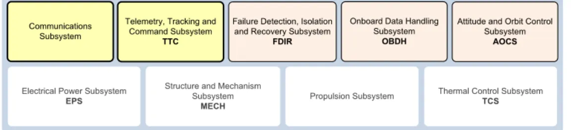
A spacecraft consists of several individual subsystems, which closely interact with each other2. Spacecraft can be divided in two principal elements, the pay-load and the avionics functions. The paypay-load consists of scientific instruments and experiments, being the motivation for the mission. Avionics may consist of the following spacecraft subsystems, here described briefly:
Communications Subsystem Provides an interface with radio frequency (RF) systems and antennas, allowing the data transfer between the space ve-hicle and the ground control. The data transfer is supported by (se-cure) communication protocols. The communications subsystem includes a non-executive command detection component responsible for receiving and passing all the commands originating from the ground control to the Telemetry, Tracking and Command (TTC) subsystem, which interprets and executes them [16].
1In the scope of this thesis, “online” or “in-field” means performing certain task during the
operational phase of a spacecraft, i. e., during a mission.
2The subsystems physical distribution and implementation may vary considerably between
8 CHAPTER 2. BACKGROUND
Telemetry, Tracking and Command Subsystem (TTC) Executes the spacecraft telemetry, telecommand and control functions. It receives and processes commands to control the spacecraft and to operate the payload, as well as housekeeping and science data originating from the ground control (passed through the communications subsystem) or other spacecraft sub-systems [17,18].
Figure2.1presents the common spacecraft subsystems, highlighting the sub-systems relevant to follow the development of this thesis. These, represented in the top of the figure, correspond to the subsystems responsible for the space vehicle control and can be somehow managed by software. At the bottom are rep-resented the subsystems associated in the first instance to the mechanical part of the spacecraft. This representation of spacecraft organization was adapted from Magellan space flight system functional block diagram that can be found in [17].
Figure 2.1: Structural organization of spacecraft subsystems
The remaining subsystems included in spacecraft, although with no direct relevance to this work, are the following:
Failure Detection, Isolation and Recovery Subsystem (FDIR) Is responsible for switch between onboard components in the presence of failures and ensure that a failure with origin in a certain component, such as the payload, does not propagate to other spacecraft subsystems. The main goal of FDIR is to effectively detect faults and accurately isolate them to a failed component in the shortest time possible [19]. If a single failure is detected and can be isolated, FDIR switches to a redundant component, marking the failed one as unhealthy [20].
Onboard Data Handling Subsystem (OBDH) Is responsible for collect, store, process and format spacecraft housekeeping and mission data for downlink or to be used by onboard computers and other spacecraft subsystems [16,5].
Attitude and Orbit Control Subsystem (AOCS) Has as its prime purpose stabi-lize the main structure of the spacecraft correctly and orient it in desired
2.2. Onboard computers 9
directions during the mission [18]. This requires the vehicle to determine its attitude, using sensors, and control it, using actuators (e. g., reaction wheels; thrusters) [16]. It monitors and modifies the spacecraft attitude and trajec-tory to meet mission objectives despite disturbances during on-orbit opera-tions.
Electrical Power Subsystem (EPS) Generates and stores all of the spacecraft’s power, feeding the other spacecraft subsystems. Solar panels are used to derive electricity from the sunlight [18,21].
Structure and Mechanism Subsystem (MECH) Supports the mechanics of the other spacecraft subsystems [5].
Propulsion Subsystem Is composed by rocket engines and thrusters that are used to accelerate spacecraft, make trajectory correction maneuvers, and maintain the spacecraft in its orbit [22].
Thermal Control Subsystem (TCS) Provides reliable temperature control to ac-commodate variations in the spacecraft heat load thus maintaining the tem-peratures of each component on the spacecraft within their allowable lim-its [21].
The launch vehicle plays an important role in a mission as it carries the space-craft through the Earth’s atmosphere and places it in orbit. Manned spacespace-craft must also include a life support subsystem, which consists of a group of devices that allow a human being to survive in space. The mission management and re-mote support to space vehicles is done on Earth by the Mission Control Center (MCC), commonly referred to as ground segment. The ground segment is some-times seen as a spacecraft component as it is vital to its operation [18].
A complete description of all spacecraft subsystems including their compo-nents and operations can be found in [18]. Design of spacecraft and mission anal-ysis aspects are addressed in [16].
2.2
Onboard computers
The space technology has evolved greatly over the past decades. Besides the no-table advances in energy-conversion technologies as well as in many other areas, the electronic computers and software have occupied the first places during this period [18]. The space industry has quickly assimilated the emerging technology, which revolutionized the autonomy and flexibility of spacecraft, and allowed to
10 CHAPTER 2. BACKGROUND The production of the onboard software follows formal documentation such as national and international standards, hardware/software control documents, specifications and user manuals. Code reuse in different missions and space-craft has turned to be a common practice. The missions are defined by advanced software due to its complexity, and the flight software is developed following approaches identical to those used to develop terrestrial control applications [18]. Onboard computers (OBCs) are designed to accomplish requirements for re-liability, complex data organization, autonomous decision-making, intensive sig-nal processing and multitasking [24].
Spacecraft should have a high level of autonomy since they may spend some time out of range of any ground station3. For example, Low Earth Orbit (LEO) polar orbiter satellites spend only one hour per day over a mid-latitude ground station [18]. This way, the investment on onboard software should not be under-estimated.
In the past, spacecraft were designed to have OBCs, i. e., CPUs and micro-controllers, in all major subsystems and payloads, being each OBC responsible for a spacecraft function [25]. Although, a new generation of space vehicles, en-abling reduced size, weight and power consumption (SWaP), has been adopted, and nowadays typical spacecraft have a single OBC to handle with all computa-tional functions. The transition from federated architectures to integrated modu-lar avionics (IMA) motivated the use of time- and space-partitioned (TSP) archi-tectures in spacecraft computational systems, to implement the logical separation of each spacecraft function [26,2].
The CPUs used in spacecraft must be highly reliable and very durable. Actu-ally, spacecraft designers opt to use microprocessors that have been largely tried and tested (according to the MIL-STD-883 standard, for instance, to insure re-liable operation [27]), instead of using the latest and greatest chips. Spacecraft OBCs use 32-bit or 64-bit microprocessors programmed using secure and certi-fied methods and tools. Microprocessor programs are written in languages such as C, C++ or ADA.
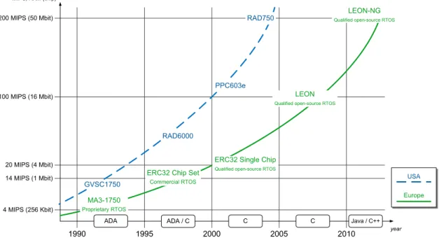
Table2.1presents some examples of CPUs used in different spacecraft [25,28]. Some spacecraft use radiation-tolerant versions of processors found in common computers whereas others employ processors especially developed for space use such as those from the SPARC LEON family [29]. Figure2.2, adapted from [30], represents the evolution of onboard microprocessors used in (European and North American) space vehicles over the years, presenting the values for million in-structions per second (MIPS) and typical Random-Access Memory (RAM) chip size for a type of processor. This graphic is complemented with the
2.2. Onboard computers 11
ming languages of the flight software and the type of real-time operating systems (RTOS) used.
The interaction between the several spacecraft subsystems may be done using controlled area network (CAN) buses. The processing power and storage avail-able onboard follows those found on Earth, however, techniques of data compres-sion are used in order to spare as much storage space as possible [18]. Typically, data is stored in RAM or Flash solid-state memories, operating on a block or file basis. Read-Only Memory (ROM) is built into the OBC before launch and con-tains the basic instructions and safe guard modes during operations [17].
Table 2.1: CPUs used in spacecraft
Spacecraft and launch year
CPU description
Viking (1976) RCA 1802 (built with Silicon-on-Sapphire
which is much more stable in a radiation environment)
Voyager 1 and 2 (1977) RCA 1802
Space Shuttle (1981) Intel 8086 and RCA 1802, later Intel 80386 (uses the APA-101S computer)
Galileo (1989) RCA 1802
Hubble Space Telescope (1990)
Originally a DF-224 (8-bit) and now a 80486
Pathfinder (1996) BAE RAD6000
International Space Station (ISS) (1998)
Intel 80386SX-20 w/ Intel 80387 (there are several computers on the ISS. The most im-portant are the common computers which use the i386)
Cluster (2000) 1750A (MIL-STD 16-bit non-RISC CPU)
Spirit and Opportunity Rovers (2003)
BAE RAD6000
SMART-1 (2003) ERC32 (version of SPARC V7 enabling the
12 CHAPTER 2. BACKGROUND Onboard memory types and typical capacity can be classified as follows:
EPROM (Erasable Programmable Read-Only Memory) Hosts the board boot and initialization software (typically 16 – 256 KiB4).
E2PROM (Electrically Erasable Programmable Read-Only Memory) / Flash Hosts the mission software and boot container (typically 2 – 8 MiB4).
SRAM (Static Random-Access Memory) Contains the executing software and variables (typically 4 – 16 MiB).
DRAM (Dynamic Random-Access Memory) Is typically used for store large amounts of data (typically 16 – 512 MiB).
Figure 2.2: Onboard processor evolution
Onboard data storage, performed by the OBDH subsystem, is achieved using solid-state memories, namely Flash memories [30]. Data storage is usually a re-quired feature in spacecraft computational infrastructure since the data collecting rate and volume could exceed the capacity of the link with the ground segment, as well as its availability [5, 18]. Data coding and error correction techniques are used to maintain the integrity of the data. The OBC memory is organized in the same way that is done in storage disks found in terrestrial computers, with data arranged hierarchically and files identified by name.
41 kibibyte (KiB) = 210bytes = 1024 bytes; 1 mebibyte (MiB) = 220bytes = 1024 kibibytes. This
corresponds to the prefixes for binary multiples defined in the IEC 60027-2 standard specifica-tion [31]
2.2. Onboard computers 13
Spacecraft flight software is integrated in high reliable and robust real-time operating systems, such as Wind River VxWorks5 or Real-Time Executive for Multiprocessor Systems6 (RTEMS). RTEMS is particularly interesting for use in space onboard software systems given its qualification for spaceborne applica-tions [32]. Flight software associated to a certain spacecraft function, such as AOCS or TTC, usually does not exceed few hundreds of KiB [33].
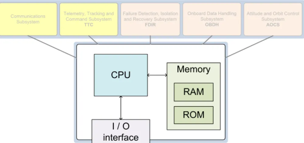
The components of a space vehicle computational infrastructure described throughout this section are illustrated in Fig.2.3. This scheme embraces a space-craft structural organization where a single CPU handles the execution of several spacecraft functions.
Figure 2.3: Simplified onboard computational infrastructure based on a unique CPU
As long as the spacecraft is visible and available from Earth it is tracked by real-time software operating in the associated ground station. With the ability to access the several spacecraft OBCs from ground segment, one may calibrate the spacecraft parameters, adjust the control algorithms and upload new functions or control software to enhance performance or adapt to new requirements. Nowa-days, there is a trend in space industry to adopt commercial off-the-shelf (COTS) products in ground stations in order to reduce costs. Concerning the spacecraft equipment, the adoption of COTS components is also related to achieving bet-ter performance results. Although, the inbet-teraction with standard components requires additional interface mechanisms [34].
Unlike past practice, designing spacecraft computational systems supporting advanced interactions with the ground segment, which may include operations such as the modification and debug of the flight software, may prove to be a measure of great importance particularly with regard to overcome the occurrence of failures [18,5].
14 CHAPTER 2. BACKGROUND
2.3
Common faults in spacecraft
During the course of a mission, it may be useful or even necessary to introduce new functions or modify existing ones in order to deal with unexpected events. An early example where such features had an essential role was the NASA’s Apollo 14 mission [35]. Prior to the descent to Moon’s surface, the Antares lu-nar excursion module had a serious problem related to a faulty abort switch. The erratic behaviour of the switch could cause the onboard computer to order the spacecraft to climb back into orbit. The solution approached to overcome this issue involved reprogramming the flight software to ignore the false abort com-mand. The software modifications were transmitted via voice communication and the changes were manually entered by the spacecraft crew. These kind of episodes in the history of space missions highlighted the importance of repro-grammability as a required property in space systems [33].
Along with the rising processing power and complexity of OBCs, the poten-tial for software errors leading to spacecraft failures increased. The causes of software failures may be systematic, however the faults occur randomly in time. Typically, the software errors are originated by (i) inadequate system and soft-ware engineering, (ii) inadequate review activities, (iii) ineffective system safety engineering, (iv) inadequate human factors engineering, and (v) flaws in the test and simulation environments [36,18].
Failures in space missions
The study and analysis on spacecraft failures done in [5], based on information retrieved from various sources, over a set of on-orbit spacecraft failures occurred in 129 spacecraft between 1980 and 2005, revealed that many spacecraft suffer unrecoverable failures in early times after their launch and others, despite the oc-currence of several failures, exceed their expected lifetime after applying failure recovery procedures. The purpose of the work described in [5] was to estimate the impact of failures on the mission and identify the critical subsystems and re-current failure modes. The failure analysis fell over the following subsystems groups: AOCS; EPS; OBDH and TTC; MECH, payload and some other miscella-neous subsystems. The results revealed that the software failures represented a small percentage of the overall spacecraft failures when comparing to the failures caused by electrical and mechanical spacecraft components.
The spacecraft failures caused by software errors, although, can be more eas-ily fixed if the system supports software patching and modification. For example, during the first European lunar mission, ESA SMART-1, software modules con-trolling the electric propulsion which have suffered anomalies, for instance in
2.3. Common faults in spacecraft 15
the error detection and correction algorithm, were subjected to adjustments and onboard software patching in order to overcome the adverse situation [22].
With respect to the impact of spacecraft failures in the mission itself, nearly 40% of the failures analysed resulted in catastrophic events, such as the loss of the mission, and the percentage of mission degradation rises to about 65% [5]. This supports the recommendations for the development of more flexible aerospace systems and the adoption of trusted software verification and validation (V & V) techniques [5,16]. The SMART-1 mission benefited greatly from the spacecraft ca-pabilities to handle software modifications and parameter tunings. Nonetheless, not all the parameters offered flexibility, which caused a negative impact in the mission in specific situations. For example, a malfunction of sensitivity to radia-tion in EPS inducing shutdowns could have been solved modifying the software not to trigger the alarm, thus avoiding the EPS shutdown and the waiting time to restart [22].
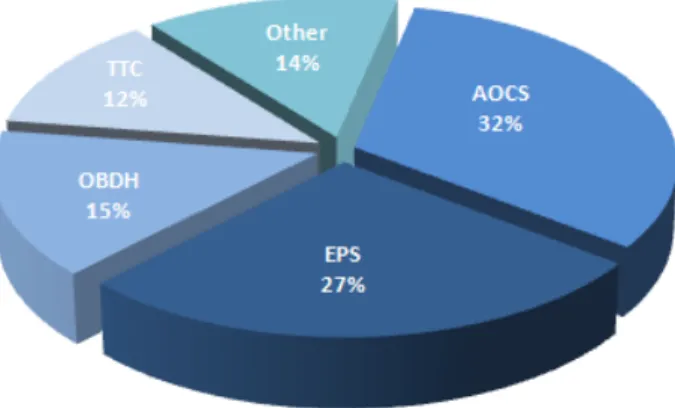
In the graphic of Fig.2.4 are represented the percentages of the most signifi-cant spacecraft subsystems affected, as they appear in [5]. AOCS is the subsystem most affected (32%). Most of the AOCS anomalies are caused by environmental conditions and can be overcome via software patches [22]. AOCS is followed by the EPS (27%), OBDH (15%), TTC (12%) and other spacecraft subsystems (the remaining 14%).
Figure 2.4: Percentage of subsystems affected during a mission
Temporal considerations
A space mission is composed by several phases. The launch phase concerns all the preparations for spacecraft launch and the launch itself. The failures occurred during this phase are the launch failures. After the launch, the spacecraft en-ters the cruise phase where are performed diverse operations such as real-time
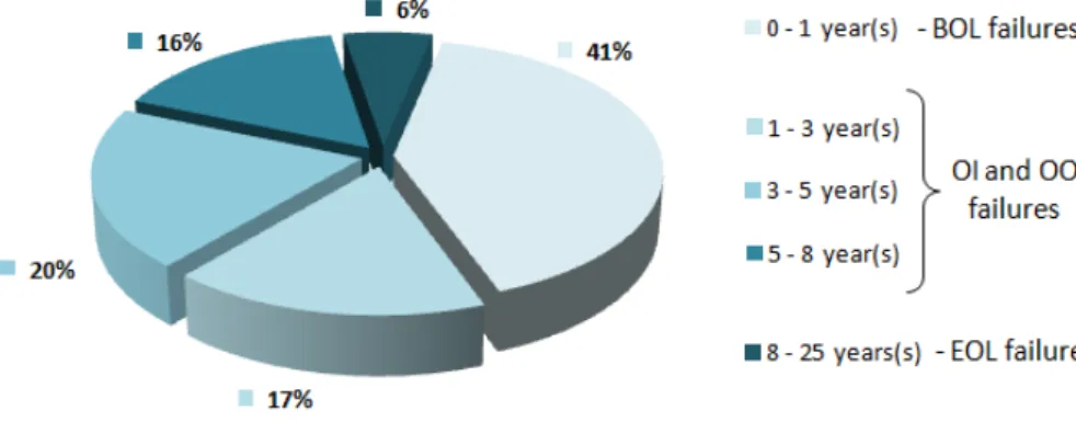
16 CHAPTER 2. BACKGROUND The encounter phase includes all the operations related to planetary orbit inser-tion, descent and landing, and sampling, for example. Depending on the state of spacecraft health and mission funding, the mission cruise and encounter phases may be extended [17]. Failures occurred during the operational phases can be grouped in beginning-of-life (BOL) failures; orbit insertion (OI), either Earth or distant planets and on-orbit (OO) failures, and; end-of-life (EOL) failures [5,37].
BOL failures include the in-orbit checkout. OI failures happens during the spacecraft orbit insertion maneuver, i. e., deceleration or acceleration maneuvers to allow the spacecraft to be captured into orbit. OO failures occur during space-craft operational events while on orbit. EOL failures correspond to the spacespace-craft consumable depletion or component obsolescence.
The time to failure is here classified as follows. BOL failures concern all ures occurred in the first year of the mission, that correspond to 41% of all fail-ures, suggesting insufficient testing or inadequate modeling. OI and OO failures are those occurred between the second and the eighth year, totaling 53%. EOL failures happen from the eighth year forward, corresponding to only 6% of all failures [5]. The graphic of Fig.2.5shows the relation between the percentage of failures and the time to failure after the spacecraft launch.
Figure 2.5: Time to failure after launch
Spacecraft failures analysis throughout the years
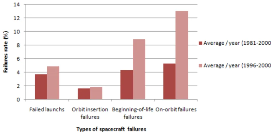
Spacecraft failures analysis throughout the years has demonstrated that the fail-ures rate can be mitigated either by the use of software patches or through on-orbit servicing (OOS), i. e., maintenance, upgrade and repair of equipment. The graphic illustrated in Fig.2.6compares the average per year in the overall study time (1981–2000) and the period during 1996–2000, according to [37]. It can be observed an increase of the number of failures in the period 1996–2000, with the exception of the OI failures, were this number remains approximately constant. EOL failures were not documented. The high failure rates during the period of
2.4. Verification and validation process 17
1996–2000 may be justified with the existence of more extensive and accurate fail-ure reporting methods and tools, comparing to earlier dates, as suggested in [37].
Figure 2.6: Spacecraft failures during 1981–2000
2.4
Verification and validation process
In the scope of spaceborne systems and applications, the verification and valida-tion (V & V) process ensures that the developed software meets its specificavalida-tions and satisfies the requirements defined for the mission. The in-field V & V of sys-tem configurations and software components have a remarkable importance to determine whether is safe to proceed with update operations and reconfigura-tions. There are different approaches with regard to the V & V process [38, 39], although the majority of them agrees that the verification and validation should be performed during all stages of the development process. Furthermore, it may be required to extend the V & V process also to the product’s operational lifetime featuring, for instance, the possibility to perform additional tests or to verify the correctness of in-flight software updates. This implies that the spacecraft’s com-putational system should somehow support the online verification of software components, to ensure the safety and robustness of the system [40,41].
Shortcomings in requirements development and the lack of a strong V & V process can cause failures either individually, collectively, or in conjunction with other faults. For example, in Apollo 13 mission, the operating voltage of the thermostatic switches for the heaters of the oxygen tanks were modified with-out changing the voltage specification and testing the new value on the switches. This was a configuration management failure that should be detected by verifica-tion. However, the mission was a success because the lunar module, the crew and the backup systems were robust [38]. Another famous example is Space Shuttle
18 CHAPTER 2. BACKGROUND design, manufacturing, testing, and operation were faulty. The low air temper-ature, which led to the explosion of Challenger, was below design expectations. The decision to launch in an environment for which the system was not designed was a validation mistake [38].
An adequate certification of software and qualification of tools is of extreme importance to meet the development requirements. Current practices of civil avi-ation, military aviation and aerospace industry, along with airborne systems and equipment guidelines remain vague, which can lead to different interpretations by the industry. The software developed for safety-critical systems must be sup-ported by qualified tools and implemented using appropriate mechanisms vided by programming languages. Despite the popularity of C and C++ pro-gramming languages in the development of safety-critical systems, these lan-guages include many features that are not suitable for this purpose, whereas Ada is well suited and meets the safety requirements [39]. Furthermore, some standards are not fully adapted for building safety-critical systems, such as the MISRA C standard, which aims to contribute to make C a safer language, al-though does not address all known fault models [42].
Besides the strict verification and validation applied to the spacecraft flight software on the ground, it is important to have safeguard mechanisms to verify the system parameters during the flight and prevent faults in unexpected situa-tions, namely due to the difficulty of simulate the space environmental conditions on the ground. The onboard validation of software is crucial to ensure whether is safe to proceed with the system execution. This is specifically important after the modification or update of software components [40,41].
The in-field safety validation may benefit from the use of contracting mecha-nisms based on formal methods [41]. This technique supports the verification of system reconfigurations and upgrades based on the analysis of the current system configuration. The methodology suggested in [41] consists on the requirements analysis of the application to be updated and on the validation of contracts during system execution, before admitting corresponding configurations to take effect in the system. This allows the modification of system parameters and the integra-tion of software components to be verified autonomously by the system itself.
Since the inability to avoid several failures on spacecraft is related to the dif-ficulty to simulate the space conditions on Earth, it is noteworthy the importance of having the possibility to perform tests under similar conditions. The work present in [43] focuses on test methodologies and simulation environments. The approach followed was designed to test software behaviour under disturbed con-ditions, simulating the space environmental conditions and attaining the greatest possible dependability of embedded software systems by reducing development
2.5. Software update 19
errors and handling runtime anomalies. This work discusses the advantages of software-in-the-loop simulations over the hardware-in-the-loop simulation ap-proach, this is, testing the real software carried out on a simulated environment versus the use of prototypes of the system under simulation.
2.5
Software update
This section addresses methodologies for system reconfiguration and software update. There are different approaches regarding the reconfiguration of aerospace applications. In airborne systems, those concern complex online or offline tech-niques to ensure the flight or mission’s effectiveness. System reconfiguration can be achieved using methods such as multi-static reconfiguration, which consists of the activation of a predefined configuration selected autonomously according to the system health state [44]. The possibility to reconfigure autonomously a space vehicle in operation through adjustments of the system control parameters and algorithms, for example, is essential to its adaptation to different mission phases. Moreover, the onboard software running on spacecraft OBCs should be up-gradeable, i. e., the system should support the update or modification of software when required. There are diverse techniques and methodologies for software update. However, the requirements for software update methodologies in space vehicles are much more strict than those required for updating terrestrial comput-ers. For instance, the updates should be executed in exact moments considered safe, their duration should be predictable and well specified, and they should not interfere with the system operation [45, 46]. The update methodology proposed in [45] preserves the original deadline guarantees, however it does not address what should be done when the timing requisites need to be modified. Software update methodologies may be built based on replication principles, such as the definition of two execution blocks to perform the updates [47].
There are several works in the literature concerning software update in the domain of real-time systems [46, 47, 48] including in the avionics industry [49], however with respect to performing updates in spaceborne systems, there is no research line established. With respect to the update of software in TSP-based systems, there were not found works covering this subject in the literature.
Techniques of dynamic software update, which refers to the modification of software components without the need to stop the current system execution, may be applied to update onboard software, although fulfilling the requirements for onboard update methodologies referred [50, 51]. An approach for dynamic up-date of applications in C-like languages is provided in [51] and focuses on the
20 CHAPTER 2. BACKGROUND cation of the code’s safety. The methodology suggested in [50] covers the timeli-ness requirements to achieve a safety environment for dynamic software update on real-time systems, running a COTS operating system. The methodology pro-posed requires the identification of specific points in time to perform the compo-nent’s update while in [48] is proposed an approach to the update of real-time applications without any presumption about the application execution times.
2.6
Summary
This chapter grouped several aspects with relevance to the development of this thesis. It described spacecraft subsystems, focusing on the onboard computers; common spacecraft mission failures; verification and validation process, and; methodologies for software update.
The following chapter will address the AIR architecture, a time- and space-partitioned environment for the development and execution of aerospace appli-cations, along with its inherent properties, and the applications development pro-cess.
Chapter 3
AIR Technology design
This chapter aims to present the AIR architecture, which will support the features proposed in this thesis, concerning the update of partition schedules and appli-cations. Beyond a general description of the architecture, this chapter details the architecture components. It explains how is defined the AIR partition scheduling. Then, it presents the composability properties of the AIR architecture. Finally, this chapter exposes the AIR applications build and integration process.
3.1
System architecture
The AIR (ARINC 653 in Space Real-Time Operating System) architecture defines a partitioned environment for the development and execution of aerospace appli-cations, following the notion of time and space partitioning (TSP), implying that the execution of applications in a partition does not affect other partitions’ time-liness and that different partitions have independent addressing spaces. The AIR architecture allows applications to be executed in logical containers called parti-tions. An AIR-based system provides a way to achieve the containment of faults to the domain where they occur using the architectural principle of robust TSP. Temporal partitioning ensures that the real-time requisites of the different func-tions executing in each partition are guaranteed. The spatial partitioning relies on having dedicated addressing spaces for applications executing on different partitions [3,4].
The AIR architecture, illustrated in Fig.3.1, relies on the AIR Partition Manage-ment Kernel (PMK) to enforce robust TSP. An operating system, herein referred as Partition Operating System (POS), is provided per partition. It is foreseen the use of different operating systems among the partitions, either real-time operating systems (RTOS) or generic non-real-time ones. Each POS is wrapped by the AIR POS Adaptation Layer (PAL) hiding its particularities from other AIR components thus ensuring flexibility and independence in the integration of each POS kernel.
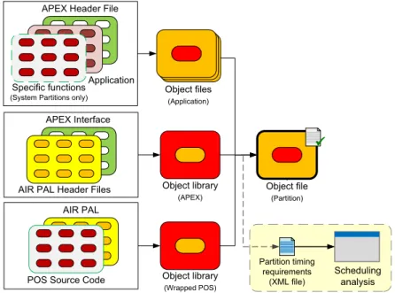
22 CHAPTER 3. AIR TECHNOLOGY DESIGN At the Application Software Layer (Fig. 3.1), applications consist of one or more processes, which make use of the services provided by an Application Ex-ecutive (APEX) interface. In addition, a partition holding system functions, may invoke also specific functions provided by the POS, thus being allowed to bypass the standard APEX interface.
Figure 3.1: AIR system architecture and integration of partition operating systems
3.1.1
Portable Application Executive (APEX) interface
The Application Executive (APEX) interface component provides a standard pro-gramming interface with a service definition derived from the ARINC 653 spec-ification [52]. The set of available services concerns partition and process man-agement, time manman-agement, intra and interpartition communication and health monitoring. The AIR architecture implements the advanced notion of Portable APEX, ensuring portability between the different POSs [53].
3.1.2
AIR Health Monitor
The AIR architecture incorporates a Health Monitor (HM) component which is responsible for handling and containing errors to their domains of occurrence. The action to be performed in the event of an error is defined by the application programmer through an appropriate error handler. This error handler is an ap-plication process that should include a systemwide reconfigurability logic, which comprises the redefinition of control parameters or the issue of a different sched-ule request, thus helping achieve system adaptability.
3.2. Schedulability 23
3.1.3
Interpartition communication
The organization of spacecraft software components in different partitions re-quires interpartition communication facilities, since a function hosted in a par-tition may need to exchange information with other parpar-titions (e. g., the commu-nications subsystem passes the commands issued by the ground mission control to the TTC subsystem, which in its turn proceeds with the suitable operations). Interpartition communication consists of the authorized transfer of information between partitions without violating spatial separation constraints [4].
3.2
Schedulability
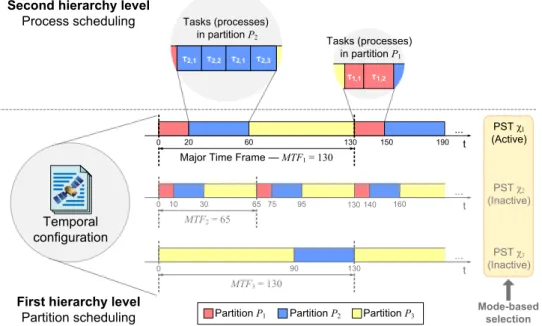
The AIR architecture uses a two-level scheduling scheme, where partitions are scheduled under a predetermined sequence of time windows, cyclically repeated over a major time frame (MTF). In each partition, the respective processes are scheduled according to the native operating system’s process scheduler (Fig.3.2).
Figure 3.2: Two-level mode-based partition scheduling
The original ARINC 653 [52] notion of a single fixed partition scheduling ta-ble, defined offline, is limited in terms of timeliness control and fault tolerance. To address this limitation, the AIR Technology design incorporates the notion of mode-based partition schedules (Fig.3.2), allowing the switch between different par-tition scheduling tables (PSTs) according to different mission phases or operating modes during the execution time, and regarding the accommodation of