Braz. J. of Develop., Curitiba, v. 5, n. 12, p.33047-33064 dec 2019 . ISSN 2525-8761
Thin walled stiffened plates: optimization using lamination parameters
Placas finas reforçadas: otimização usando parâmetros de laminação
DOI:10.34117/bjdv5n12-359
Recebimento dos originais: 10/11/2019 Aceitação para publicação: 27/12/2019
Helio De Assis Pegado
Doutor em Engenharia Aeronáutica e Mecânica pelo Instituto Tecnológico de Aeronáutica Instituição: Universidade Federal de Minas Gerais
Endereço: Av. Antônio Carlos, 6627, Pampulha - Belo Horizonte - MG, Brasil E-mail: [email protected]
Laura Tameirão Sampaio Rodrigues
Engenheira Aeroespacial pela Universidade Federal de Minas Gerais Instituição: Universidade Federal de Minas Gerais
Endereço: Av. Antônio Carlos, 6627, Pampulha - Belo Horizonte - MG, Brasil E-mail: [email protected]
ABSTRACT
The leading guide, when it begins the design of aeronautical structures, is to reduce its weight to the minimum necessary. The use of composite materials in aeronautical structures has provided a considerable reduction in weight while maintaining the same structural strength. However, due to the anisotropy of the material, its mathematical model is complex and involves large matrices. In this work, a carbon fiber reinforced plate is optimized that withstands buckling compression loads and has its weight reduced to the minimum required. The Nastran optimizer will be employed whose objective function involves minimizing the weight of the structure to withstand a predefined load without buckling, and the thickness of the plate and stiffener are the design variables. Initially, the optimizer is used on an aluminum and carbon fiber plate, and its results are compared to validate the use of the optimizer. Then the optimizer is employed to obtain the optimum lamination parameters, thickness, and dimensions of the plate and stiffener. It´s necessary to have a lamination data to get the optimum lay-up.
Keywords: Structural optimization, Composite material, Lamination parameters, Nastran sol 200.
RESUMO
O guia principal, quando inicia o projeto de estruturas aeronáuticas, é reduzir seu peso ao mínimo necessário. O uso de materiais compósitos em estruturas aeronáuticas proporcionou uma redução considerável no peso, mantendo a mesma resistência estrutural. No entanto, devido à anisotropia do material, seu modelo matemático é complexo e envolve grandes matrizes. Neste trabalho, uma placa reforçada com fibra de carbono é otimizada para suportar
Braz. J. of Develop., Curitiba, v. 5, n. 12, p.33047-33064 dec 2019 . ISSN 2525-8761 cargas de compressão de flambagem e ter seu peso reduzido ao mínimo necessário. O otimizador Nastran será empregado cuja função objetivo envolve minimizar o peso da estrutura para suportar uma carga predefinida sem flambagem, e a espessura da placa e do reforço são as variáveis de projeto. Inicialmente, o otimizador é usado em uma placa de alumínio e fibra de carbono, e seus resultados são comparados para validar o uso do otimizador. Em seguida, o otimizador é empregado para obter os melhores parâmetros de laminação, espessura e dimensões da placa e do reforçador. É necessário ter dados de laminação para obter o melhor layout.
Palavras-chave: Otimização estrutural, Material compósito, Parâmetros de laminação,
Nastran sol 200
1 INTRODUCTION
Based on the study of the composite materials, it is known that by varying the laminate sequence and the lamination angles, the properties of the material can be optimized to resist the loading to which the structural component is subjected.
Some techniques of composite materials optimization define the variation of the number of the laminate layers and the angles of lamination as design variables which is assumed that the material has orthotropic properties. However, this type of optimization involves high computational cost and consists of a nonlinear optimization process with discrete variables in a non-convex space.
To solve the problem of optimization of discrete variables of the lamination sequence of the composite materials, Miki (1993) proposed the use of lamination parameters. Its method considers that the stiffness in the plane and the flexural rigidity of the symmetrical and orthotropic laminated plates are functions of the lamination parameters, those depend on the lamination sequence.
Fukunaga et al. (1994) present an optimization approach on laminate configurations of symmetrically laminated plates to maximize buckling loads under combined loading. The relation of laminate configurations and buckling loads is clarified based on a concept of lamination parameters. Liu e Haftka (2004a) and (2004b) described an optimization procedure based on flexural lamination parameters that were used to integrate unstiffened composite panel design and wing structural design. The lamination parameters were constrained to a hexagonal domain when the amounts of 0◦, ±45◦, and 90◦ plies were given. This optimization is based on continuous flexural lamination parameters for the minimization of wing weight; meanwhile, in the second paper the parameters were used for the maximization of buckling loads. Dutra and Almeida (2015) presented an optimization method based upon a quadratic
Braz. J. of Develop., Curitiba, v. 5, n. 12, p.33047-33064 dec 2019 . ISSN 2525-8761 metamodel used to estimate the objective function. An analytical formulation to obtain the derivatives of the objective functions concerning for to the lamination parameters is shown. A composite plate subjected combined bending and torsion loads is optimized and the results are presented and discussed in terms of practical design of aeronautical structures. Quadros and Hernandes (2018) studied a Lagrange parameterization of lamination parameters for the maximization of the buckling load of a variable stiffness composite plate.
This article is structured as follows: it shows the methodology used in the optimization of the stiffened plates, the hypotheses considered, the equations used for composite panels analysis and the results obtained expressed in tables and figures.
2 OPTIMIZATION
This research involves an optimization process that uses as design variables the lamination parameters and the thickness of the plate and the stiffener, and as objective function the weight. Two stiffened plates, one made of aluminum and one made of carbon fiber, were analyzed. The optimizer used is a subroutine of NASTRAN and its efficiency in the analysis of these stiffened plates are tested on the aluminum plate. These results are compared with the Farrar Efficiency Factor (Niu,1997) and the efficiency of this optimizer is shown. After its validation, the NASTRAN optimizer (SOL 200) is used for plate optimization in composites having the lamination parameters and the thicknesses as the design variables.
2.1 ASSUMPTIONS
The model satisfies the Classical Laminate Theory and: i. each ply is quasi-homogeneous and orthotropic;
ii. the laminated is thin and its lateral dimensions are much larger than its thickness and are loaded only in-plane (plane stress condition);
iii. displacements are small when compared with the laminate thickness: ;
iv. the laminate is symmetrical and balanced, which means, the lamina is arranged in pairs (+q and -q ) above and under of the middle plane;
v. this laminated plate satisfies the Ten-Percent Rule, where the number of plies in each lamination angle (0, ±45 and 90 degrees) is at least 10 percent of the total of plies.
Braz. J. of Develop., Curitiba, v. 5, n. 12, p.33047-33064 dec 2019 . ISSN 2525-8761 2.2 MODELLING OF LAMINATED PLATE
Figure 1. Lamination Sequence (Liu, Hakka and Trompette,2004)
The methodology adopted for the use of lamination parameters by Rodrigues (2018) and follow the model showed in Figure 1 consider a lamination sequence in each lamina is orthotropic as represented in Equation 1:
[
(
±θn)
Nn/...(
±θ2)
N 2/(
±θ1)
N 1]
s (1)According to MIKI (1993), the lamination parameters are good choices to be used as design variables when developing a laminate, since it is possible to obtain a viable region of the lamination parameters in a two-dimensional plane. When there is one symmetric and orthotropic laminate, the stiffness in the plane (matrix A – Eq 2) and flexural rigidity (matrix D – Eq2) become functions of the lamination parameters, which are functions of the sequence of lamination (Figure 1). Since this laminate is symmetrical, the rigidity due to the coupling (matrix B – Eq2) is zero.
[
M N]
=[
A B B D]
[
εo κ]
(2)Where M is the intensity of the pure bending and shear moments per unit length, and N is the direct or shear forces per unit length produced by in-plane loads. The stiffness matrix A, B e D can be expressed by the invariant of stiffness U and twelve lamination parameters -
x (Rodrigues,2018). When considering the laminate as symmetrical, the stiffness coupling
matrix B will be zero and then the number of lamination parameters will be reduced to 8. Similarly, several manufacturers adopt as a design practice that the slides are orthotropic and
Braz. J. of Develop., Curitiba, v. 5, n. 12, p.33047-33064 dec 2019 . ISSN 2525-8761
may have only 0 ° / 45 ° / 90 ° as the lamination angles, thus reducing the lamination parameters to 6. Therefore the following expressions are used for the stiffness in the plane and flexuralstiffness:
and (3)
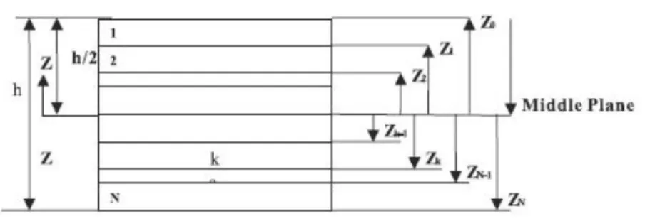
The lamination parameters are presented in Equation 4 where the superscript D represents the D matrix and the superscript the correspondent matrix.
ξ[ 1,2,3]A = 1 h− h/2
∫
h/2 [cos2φ,cos4φ,sin2φ]dz ξ[ 1,2,3]D = 12 h3− h/ 2∫
h/2 [cos2φ,cos4φ,sin2φ]z2dz (4)After analyzing the equations 2 e 4, can be observed that the lamination parameters ξ3
D
are related to the terms D16 e D26 of the matrix [D]. These terms don't contribute significantly
to the analyzes and how the fail by buckling that will be studied, the parameter ξ3
D
will can to be neglected. And since the laminate is symmetrical and balanced concerning the middle plane, the lamination parameter ξ3
A
will not be taken into account in this study, therefore, the following lamination parameters will be considered during the optimization of the panel:
ξ1A = 1 h− h/2
∫
h/ 2 cos2φdz , ξ2A= 1 h− h/2∫
h/ 2 cos4φdz ,Braz. J. of Develop., Curitiba, v. 5, n. 12, p.33047-33064 dec 2019 . ISSN 2525-8761 Though laminating parameters allow a continuous optimization of the laminate with a relatively low number of design variables, they do not allow the association of the constraints with the discrete nature of the thickness at lamination angles (LIU; HAFTKA; TROMPETTE, 2004). For example, with the use of this method, it is not possible to avoid the accommodation of several laminas in a sequence with the same direction of the lamination angle. Therefore, after optimizing the laminate using the lamination parameters, it will be necessary to use a laminate database to obtain the discrete laminate solution.
The composite panel that has a sequence of angles of laminas is symmetric for the middle plane is called symmetrical laminates as described by (MIL-HDBK-17-3F, 2002) and (Niu,1992) is the major advantage of using symmetrical laminate is the decoupling between the membrane behavior and the bending of the structure. In a symmetrical laminate, according to the notation shown in Figure 2 and according to Equation 2, the laminate matrix [B] cancels out.
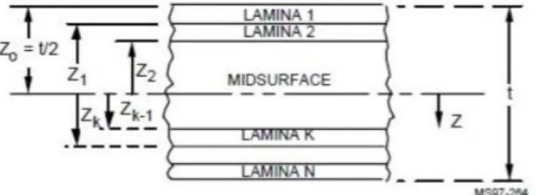
Figure 2: Notation for Laminate Thickness and Lamination Sequence (MIL HDBK-17-3F,2002)
Font:
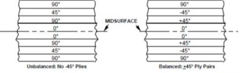
Balanced laminates (Figure 3) are those in which all layers, minus 0° and 90°, are accommodated in + θ and -θ pairs above and under the middle plane of the laminate. For the set of laminates composed of layers with angles 0/±45/90, each lamina of +45◦ must be accompanied by one of -45°.Balanced laminates have advantages similar to those of symmetrical ones. One of them is that the membrane coupling between normal and shear behavior in the plane of the structure is removed, since both coefficients, A16 and A26, are equal
Braz. J. of Develop., Curitiba, v. 5, n. 12, p.33047-33064 dec 2019 . ISSN 2525-8761
Figure 3: Balanced e Unbalanced Laminate (MIL HDBK 17-3F,2002)
The 10% rule was followed in several structural projects of composite materials and demonstrated good results and thus, it is adopted until the present day. The 10% rule dictates that at least 10% of the final laminate layers have lamination angles (0°, ± 45°, and 90°). The use of this design practice produces laminates that are more robust and they are less susceptible to the fragility associated with strictly orthotropic laminates (Bailie; Lay; Pasricha, 1997).
2.3 NASTRAN SIMULATION
The design variables are the thicknesses of the skin and the stringer, as well as the lamination parameters (ξ). For these simulations, it was used the type MAT2 that defines the material properties for linear, temperature-independent, anisotropic materials for isoparametric shell elements and the element PSHELL, that defines the membrane, bending, and transverse shear properties of shell elements. In order to impose the restrictions DCONSTR was used and the objective weight minimization function is launched using the DESOBJ command. Three NASTRAN solutions are used: the optimization solution (SOL200), the static one (SOL101) and the buckling solution (SOL105).
2.4 METHODOLOGY 2.4.1 Theoretical Analysis
This model was developed using the Niu (1997) methodology that is summarized in Rodrigues (2018). The optimum point is represented by Farrar´s efficiency factor and the reinforced plate dimensions are obtained using it. Below are presented the principal assumptions and equations used to estimate the dimensions.
Braz. J. of Develop., Curitiba, v. 5, n. 12, p.33047-33064 dec 2019 . ISSN 2525-8761 i. The panel is long enough to allow it to be treated as a single column, which means, there are no restrictions imposed on the longitudinal edges of it;
ii. the panel has a support fixation at the end of its structure, concerning the length L however, L is considered as the effective length of the panel;
iii. the rib-reinforced do not constrain the plate bucking.
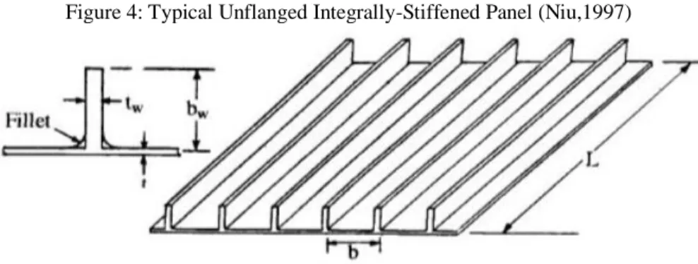
Figure 4 shows a typical unflanged integrally-stiffened panel (Niu,1997), where t is the thickness of the skin, b is the stiffener spacing, bw is the stiffener depth, L is the pin-ended bay length, f is the applied stress, fi is the panel section initial buckling stress and fE is the Euler instability stress.
Figure 4: Typical Unflanged Integrally-Stiffened Panel (Niu,1997)
According to Niu (1997), Farrar´s efficiency factor is:
F= 1.314Rb 3 Rt
(
4+ RbRt)
1/ 4 1+ RbRt(
fi fo)
1/4 (6)where Rb is the relationshipRb=
bw b , Rt=
tw
t , fois the initial buckling stress of a long plate
of stiffener spacing, b, and skin thickness, t, simply supported along its edges
fi= 3.62Et
(
tb
)
2
.
The Farrar´s efficiency factor can be written as:
F= f ( L NEt
)
1/2
where L is the length of the panel and Et is the tangent modulus. Niu (1997) uses auxiliary variables to solve this problem graphically:
Braz. J. of Develop., Curitiba, v. 5, n. 12, p.33047-33064 dec 2019 . ISSN 2525-8761 J1= b( Et NL3) 1/ 4 , J2= tW( Et NL) 1/2 , J3= bW( Et NL3) 1/4 and J4= t( Et NL) 1/ 2 . (7)
These variables are obtained assuming a value to Rb. F and the optimal point Rb are found using diagrams (Niu,1997).
An optimized extruded Al 2024-T3 reinforced panel was designed, following the Farrar’s Efficiency Factor methodology proposed by (Niu, 1997), which resists a compression load of 100000 N/m (269777 lbs / in). The methodology proposed by the author was followed and the results are presented in the space reserved for results.
2.4.2 Metallic Panel - Finite Element Method
After to apply MSC NASTRAN to optimize a reinforced plate with the same dimensions of that calculated by Farrar´s Efficiency Factor these results were compared. Then, the differences were analyzed and the model was considered validated. Hereafter, the optimizer was applied to calculate the optimal dimensions to composite and metallic reinforced plate.
A finite element model to simulate a reinforced panel was developed as shown in Figure 5 to perform the optimization analysis. This model was developed using only one type of material, both for the skin and the stringer (Al 2024 T3), with the characteristics as shown in Table 1.
Table 1: Material Property (RICE,2003 Properties of Al 2024-T3 Extruded
Tangent Modulus (Et) 66.2x10³ N/mm2 9.16x10³ Ksi
Poisson´s Ratio ( ) 0.33 0.33
Braz. J. of Develop., Curitiba, v. 5, n. 12, p.33047-33064 dec 2019 . ISSN 2525-8761
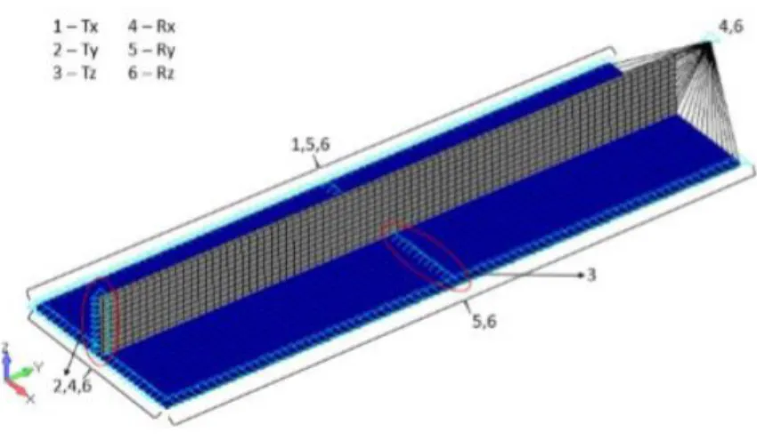
Figure 5: Model of Stiffened Panel – NASTRAN - FEMAP (Rodrigues,2018)
The model of Figure 5 was developed with plate-like elements (PLATE) for the stringer and the skin and with two distinct properties, is a property for the skin and another property for the stringer, since they have different thicknesses. Figure 6 shows the boundary conditions employed in NASTRAN model.
Figure 6: Boundary Conditions – FEMAP (Rodrigues,2018)
Concerning the loading applied in the model, it was defined that the reinforced panel would only be subjected to a compression load, without shearing. And therefore, this compression load was applied as shown in Figure 7, using a rigid element of type RBE2 to distribute the load equally to the nodes of the plate members which are located at one end of the stringer.
Braz. J. of Develop., Curitiba, v. 5, n. 12, p.33047-33064 dec 2019 . ISSN 2525-8761 About optimization, the goal was to minimize the weight of the structure. Meanwhile, during the optimization solution, the constant compression load was maintained, the thicknesses of the skin and the stringer were changed. This optimum structure had to withstand the compression load without buckling, using a constraint within the optimizer (SOL 105).
2.4.3 Composite Plate Optimization
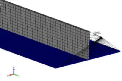
This model was developed using carbon composite material, but with two properties of different materials. Since there is one material exclusively for the skin and another material for the web of the stringer, according to Figure 8.
Braz. J. of Develop., Curitiba, v. 5, n. 12, p.33047-33064 dec 2019 . ISSN 2525-8761 The stringer base is composed both of the skin material and the stringer web material, as shown in Figure 9. The model was developed with plate-type elements (PLATE) for the stringer and the skin, and with two properties, one is a property for the skin and another property for the stringer. However, there is a given thickness for the stringer tweb, one for the skin t and one for the base of the stringer twbase.
The reinforced panel was modeled with a stringer, the boundary conditions applied in the composite reinforced finite element model are the same as those applied in the metal reinforcer model.
Concerning the loading applied in the model, it was defined that the reinforced panel would only be subjected to a compression load, without shearing. So, this compression load was applied in the same way as applied to the metal material reinforced model, as shown in Figure 7.
Figure 9: Composite Stiffener Base (Rodrigues,2018)
As with the metal plate, the objective function was to minimize the weight of the structure. Therefore, during the optimization solution, the compressive load was maintained constant, the thicknesses of the skin and the stringer varied. In the optimization of the reinforced panel, the lamination parameters of both the skin and the reinforced panel were also varied. It was obtained a structure that would support the compression load, respecting the constraint of buckling within the optimizer (SOL 105).
Braz. J. of Develop., Curitiba, v. 5, n. 12, p.33047-33064 dec 2019 . ISSN 2525-8761 3 DISCUSSION AND RESULTS
The results obtained in the research are presented in the form of Tables and Figures. The results that prove the validity of the adopted model are presented initially. Afterward, the results are presented regarding the optimization of a reinforced plate in metallic material and finally, the results referring to the optimization using the lamination parameters.
3.1 THEORETICAL MODEL RESULTS
The results of the theoretical model were obtained following the methodology of Niu (1997) with the use of several abacus, most of these built after the tests. Rodrigues (2018) shows how to calculate with the application of Farrar Efficiency in Table 1. The Table presents two optimal points and the mass evaluated is the same.
Figure 10 shows the result after optimization. Initially, the results obtained by the NASTRAN optimizer for a metal plate subjected to a compression force are presented in Tables 1 and 2.
Table 1: Theoretical Model Results and Input Data (Rodrigues,2018)
Input Data N (N/mm) N(lbs/in) Rb
1,000 5,710.2 0.33
Partial Results
optimum F Rt J4 f (psi) Et (psi)
1 0.65 1.20 1.2 40,000 5.4x10⁶ 2 0.65 2.7 0.8 40,000 5.4x10⁶ Final Results Optimum point M (kg) t (mm) tw (mm) 1 0.717 3.884 4.661 2 0.717 2.590 6.993
Braz. J. of Develop., Curitiba, v. 5, n. 12, p.33047-33064 dec 2019 . ISSN 2525-8761
Figure 10: Reinforced Metallic Plate Results obtained by NASTRAN (Rodrigues,2018)
Table 2 presents a comparison between the two “optimals” points of the theoretical model and the finite element model. This difference, probably is due to the assumptions to apply the theoretical model considered an optimal skin-stringer panel with the Farrar efficiency factor of 0.65. Point 2 presents a result closer than the NASTRAN Results. A reinforcement optimization model was developed in a metallic material, in which the material had the same tangential modulus Et properties of the theoretical model since the NASTRAN SOL105 is linear, which means, it does not consider the plasticity of the material. The design variables are the thicknesses of the skin and the stringer, as well as the lamination parameters (composite model).
Table 2: Comparison Theoretical and NASTRAN Model
Theoretical 1 Difference Theoretical 1x Nastran
Theoretical 2 NASTRAN Difference Theoretical 2 x Nastran
t(mm) 3.884 53% 2.590 2.544 1%
tw (mm) 4.661 22% 6.993 5.724 18 %
m (kg) 0.717 18% 0.717 0.587 18%
3.2 LAMINATED AND METALLIC REINFORCED PANEL
The metal panel template that was used to validate the results will not be presented in this summary. After performing the simulation in NASTRAN the results were transcribed in Table 1 and Table 2 are obtained. Table 1 shows the optimized thicknesses of the metallic and composite plate. It is observed that the obtained thicknesses are very close, except for the
Braz. J. of Develop., Curitiba, v. 5, n. 12, p.33047-33064 dec 2019 . ISSN 2525-8761
thickness of the stiffener whose difference between the metal and the composite is around 25%.
Table 3: Results of NASTRAN Optimizations
Model Plate (mm) Stiffener (mm) Stiffener Base Thickness
(mm) Metallic 3.092 2.165 4.174 Laminated 2.928 2.611 4.234
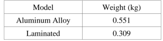
As expected, the weight of the metal structure is well above that of the laminated plate as shown in Table 2. The structure weight was evaluated using the density mass of materials (ρAl
= 2.8x10⁻³g/mm3 and ρ
lam = 1.56x10⁻³g/mm3). This plate must resist the compressive loading applied without buckle. Figure 12 shows the buckling modes obtained after the NASTRAN simulation.
Table 4: Structure weight after optimization (Rodrigues,2018)
Model Weight (kg) Aluminum Alloy 0.551
Laminated 0.309
Figure 11 presents the model used in simulation with the stiffener and the base, after the optimizations process. The thicknesses obtained by the NASTRAN optimizer can be analyzed in Table 4.
Braz. J. of Develop., Curitiba, v. 5, n. 12, p.33047-33064 dec 2019 . ISSN 2525-8761
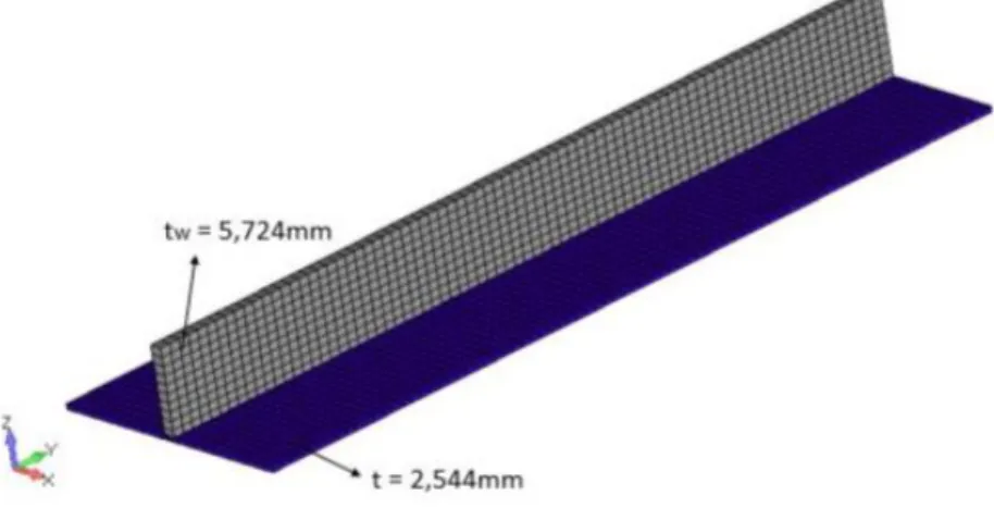
The composite plate is optimized and its results are shown in Figure 12. These thicknesses were calculated with NASTRAN Optimizer and are shown also in Table 4 for comparison with the metallic model.
Figure 12: Optimized Thickness Composite Stiffness Panel (Rodrigues, 2018)
Table 4 presents the lamination parameters obtained after the optimization. With a database of laminates, it is possible to obtain the laminates that have the same properties (lamination parameters).
Table 4: Lamination Parameters obtained after the Simulation (Rodrigues,2018)
Structural Component ξ1A ξ2A ξ1D ξ2D Stringer 0.3182 0.0348 0.0537 -0.0625 Skin 0.2560 0.0529 -0.0851 -0.0913 Base 0.2853 0.0443 0.0215 -0.199
The use of NASTRAN allows showing the buckling analysis to the optimized panel. This result is shown in Figure 13using a color code to identify the regions.
Figure 13: Buckling Analysis Composite Stiffness Panel– NASTRAN (RODRIGUES, 2018)
Braz. J. of Develop., Curitiba, v. 5, n. 12, p.33047-33064 dec 2019 . ISSN 2525-8761 4 CONCLUSIONS
The use of lamination parameters allowed a consistent optimization of the composite stiffened panel to be performed and prevented discrete optimization based on the number and direction of each laminate blade.
The results were consistent and, from the analysis of the metallic material, it is observed that the differences between the theoretical model of the Farrar Efficiency Factor and the result optimized by NASTRAN are very close.
As expected, the weight of the composite component is lighter and the result was obtained more quickly using the lamination parameters and using the NASTRAN optimizer, which is the most used in the aeronautics industry.
REFERENCES
Bailie J; Ley, R.; Pasricha, A, 1997. “A summary and review of composite laminate design guidelines”. National Aeronautics and Space Administration, Final, n. 22.
Dutra, T.A. and Almeida, S.F.M., 2015. “Composite Plate Stiffness Multicriteria Optimization using Lamination Parameters.” Composite Structures, Elsevier, v.133, p. 166-177.
Fukunaga,H., Sekine,H., Satot, M. and Lino, A..,1995. “Buckling Design of Symmetrically Laminated Plates using Lamination Parameters.”Computer and Structures, Pergamon, v.57, n.4, p. 643-649.
Miki, M., 1993. “Optimum Design of Laminated Composite Plates using Lamination Parameters. AIAA Journal. AIAA, v. 31, n.5, p.921-922.
Braz. J. of Develop., Curitiba, v. 5, n. 12, p.33047-33064 dec 2019 . ISSN 2525-8761 MIL-HDBK-17-3F, 2002. “Polymer Matrix Composites, Materials Usage, Design and Analyses”. Composite Materials Handbook, US Department of Defense, v.3.
Liu,B. and Haftka, R., 2004a. “Single-level composite wing optimization based on flexural lamination parameters”. Structural and Multidisciplinary Optimization, Springer, v. 26, n. 1-2, p.111-120.
Liu,B., Haftka, R. and Trompette, P., 2004b. “Maximization of buckling loads of composite panels using flexural lamination parameters”. Structural and Multidisciplinary Optimization, Springer, v. 26, n. 1-2, p.28–36.
Niu, M.C-Y, 1997. Airframe Stress Analysis and Sizing. Hong Kong Conmilit Press LTD. P. 617-648.
Quadros, H.B. and Hernandes, J.A., 2018. “A Lagrange Parametrization for the Design of Variable Stiffness Laminates”.Structural and Multidisciplinary Optimization, Springer, v. 58, n. 1, p.129-137.
Rice, R. C., 2003. “Metallic Materials Properties Development and Standardization” (MMPDS). National Technical Information Service, cap 1-4.
Rodrigues, L.T.S., 2018. Otimização Estrutural de um painel reforçado utilizando parâmetros
de laminação. Trabalho de Conclusão de Curso, Universidade Federal de Minas Gerais, Belo