´
E AUTORIZADA A REPRODUC¸ ˜AO INTEGRAL DESTA TESE APENAS PARA EFEITOS DE INVESTIGAC¸ ˜AO, MEDIANTE DECLARAC¸ ˜AO
ESCRITA DO INTERESSADO, QUE A TAL SE COMPROMETE. Universidade do Minho, / /
Acknowledgements
Firstly, I would like to thank Professor Jos´e Creissac Campos, for all the help, support and encouragement throughout the research and writing of this dissertation. Thank you for being a dedicated mentor and guide, also considering that the major part of the work has been made at distance. A special thanks also to Professor Emilia Villani for the hosting and guidance provided at ITA (Instituto Tecnol´ogico de Aeronautica) and INPE (Instituto Nacional de Pesquisas Espaciais), which made this research possible.
Secondly, I thank my mother, for her endless love and support in every moment of my life.
I thank Elena for her affection and patience. Part of this thesis is yours.
I also want to thank my friends and colleagues, especially Andr´e, Iago, Pedro e Rui, for the help and advice given as much as a good laugh.
I would also like to mention my cousins, not for their help in concentrating, but for their endless cheerfulness.
Abstract
Critical software can be potentially dangerous if not well verified, leading to serious failures. Accordingly, there is a need for improved validation and verification methods in order to have guarantees about the software final product. The aim of this project is to define a more linear and organized verification and validation plan to, formally, verify the most critical parts of the OBDH (On-Board Data Handling) subsystem of ITASAT, supported by the Alloy formal language.
Alloy supports the description of systems whose state involves complex relational struc-ture. The application of Alloy and Alloy Analyzer was motivated by the need for a formal specification that is more closely tailored to state-machines, and more amenable to au-tomatic analysis. Structural and behavioural properties are described declaratively, by conjoining relations and constrains, making it possible to develop and analyze a model incrementally. Due to the high cost of using these methods, they are mainly used in the development of high-critical software where safety and security are crucial.
This dissertation presents a set of guidelines for analysis and modelling of software systems which support the creation of a formal model and allow some extra behaviours such as synchronization, interruptions and flags. A new tool, ModelMaker, was developed in order to create models using these guidelines in a more interactive way.
Resumo
O software cr´ıtico torna-se potencialmente perigoso quando n˜ao cuidadosamente ver-ificado, podendo resultar em falhas graves. Por consequˆencia, existe uma necessidade de melhorar os m´etodos de valida¸c˜ao e verifica¸c˜ao, oferecendo garantias sobre o produto final. O objetivo do presente projeto ´e a defini¸c˜ao de um plano de verifica¸c˜ao e valida¸c˜ao linear e organizado para verificar formalmente as partes mais cr´ıticas do sub-sistema OBDH (On-Board Data Handling) do Sat´elite do ITA (Instituto de Tecnologia Aeron´autica), atrav´es da linguagem formal Alloy.
Alloy permite a descri¸c˜ao de sistemas cujo estado envolve estruturas relacionais com-plexas. A sua aplica¸c˜ao e a do Alloy Analyzer justificou-se pela necessidade de uma es-pecifica¸c˜ao formal que fosse mais adapta a m´aquinas de estado e mais recetiva a an´alises autom´aticas. As carater´ısticas estruturais e comportamentais s˜ao descritas declarativa-mente, atrav´es da jun¸c˜ao de rela¸c˜oes e restri¸c˜oes, permitindo desenvolver e analisar um modelo de forma iterativa. Devido ao seu custo elevado, estes m´etodos s˜ao principalmente usados no desenvolvimento de softwares cr´ıticos, para os quais a seguran¸ca ´e um pressu-posto fundamental.
Esta disserta¸c˜ao apresenta um conjunto de diretrizes para a an´alise e modela¸c˜ao de sistemas. Estas suportam a cria¸c˜ao de um modelo formal e permitem alguns comporta-mentos adicionais como a sincroniza¸c˜ao, a interrup¸c˜ao e flags. ´E tamb´em introduzido o ModelMaker, uma ferramenta que, fazendo uso das directrizes, ajuda numa constru¸c˜ao interativa e autom´atica de modelos.
Contents
Acknowledgements v Abstract vii Resumo ix 1 Introduction 1 1.1 Motivation . . . 1 1.2 Problem . . . 2 1.3 Objective . . . 3 1.4 Contributions . . . 51.5 Structure of the Document . . . 5
2 ITASAT 7 2.1 Introduction . . . 7
2.2 ITASAT . . . 8
2.3 Architecture . . . 11
2.4 Attitude Control and Data Handling . . . 12
2.5 Conclusion . . . 13
3 V & V in Critical Systems 15 3.1 Introduction . . . 15 3.2 ESA Document . . . 17 3.3 NASA Document . . . 18 3.3.1 NASA Guidebook I . . . 18 3.3.2 NASA Guidebook II . . . 19 3.3.3 Levels of Formalisation . . . 19 3.4 Formal Approach . . . 20 3.4.1 Verification Methodology . . . 20 3.4.2 Formal Approach . . . 21 3.5 Conclusion . . . 22 xiii
xiv CONTENTS
4 Alloy 23
4.1 Introduction . . . 23
4.2 Atoms and Relations . . . 24
4.3 Alloy Logic . . . 26
4.3.1 Propositional Logic . . . 27
4.3.2 First-Order Logic . . . 28
4.4 Alloy Language . . . 28
4.4.1 Operators and Quantifiers . . . 29
4.4.2 Functions, Facts, Assertions and Predicates . . . 30
4.4.3 Run and Check . . . 33
4.5 Alloy Analysis and Analyzer . . . 34
4.5.1 Alloy Analysis . . . 35
4.5.2 Alloy Analyzer . . . 36
4.6 Conclusion . . . 36
5 Formal Model Template 37 5.1 Introduction . . . 37
5.2 Phase 1: Formal Model Template . . . 38
5.2.1 Initial Model . . . 38
5.2.2 Requirements and Facts . . . 41
5.2.3 Move your Model . . . 42
5.2.4 Synchronization . . . 44
5.2.5 System Exceptions . . . 47
5.2.6 Booleans, Integers and Flags . . . 48
5.3 Phase 2: ModelMaker Automatic Building . . . 51
5.3.1 Create a Formal Model . . . 52
5.3.2 Checking the Model . . . 54
5.3.3 ModelMaker Implementation . . . 56
5.4 Conclusion . . . 56
6 A Real Case Study! 59 6.1 Introduction . . . 59
6.2 Satellite System Modules . . . 59
6.2.1 Unreachable Survival Mode . . . 60
6.2.2 Starvation in Alignment Payload Mode . . . 61
6.2.3 Duality in Alignment Payload Mode . . . 61
6.2.4 Payload Mode Smooth Exit . . . 62
6.3 Software Modules . . . 64
6.3.1 Unreachable CM Initialization . . . 64
6.3.2 Incompatibilities in Communication . . . 66
6.3.3 OBC Sequential Output . . . 66
6.3.4 OBC Nominal Smooth Exit . . . 67
CONTENTS xv
6.4 Communication Modules - Receiver . . . 68
6.4.1 Foreground Routine - Receiver . . . 70
6.4.2 Survival Flag Interruption . . . 70
6.4.3 Memory Read and Write Pointers . . . 72
6.5 Conclusion . . . 74
7 Conclusion and Future Work 77 7.1 Conclusion . . . 77
List of Figures
1.1 Verification and Validation Model, adaptation from . . . 2
1.2 The life-cycle of Validating and Verifying the requirements using Alloy. . . 4
2.1 Mission Concept, adaptation from Larson/Wertz, Space Mission Analysis and Design Workshop [2012]. . . 10
2.2 Diagram of the ITASAT satellite system . . . 12
2.3 OBC Hardware Diagram . . . 13
4.1 Conjunction of facts (list <= 4 ∧ list < 3) . . . 32
4.2 Checking assertions with Alloy Check command . . . 35
5.1 Initial model with events . . . 39
5.2 An example of dynamic modelling simulation in Alloy model. . . 45
5.3 Action Synchronization in model A and model B . . . 47
5.4 Main model and Exception model . . . 49
5.5 “A Satellite cannot be on earth and in space at the same time”, Bool example 50 5.6 “Counter” incrementation throw Instant . . . 52
5.7 ModelMaker Interface . . . 53
5.8 State and Event addition to the model in ModelMaker . . . 53
5.9 A new model creation in ModelMaker . . . 54
5.10 Alloy file resulting as a ModelMaker output . . . 55
5.11 ModelMaker model created by ModelMaker tool . . . 56
6.1 Satellite modules ITA documentation . . . 60
6.2 Simplification in Satellite System Modules ITA . . . 62
6.3 Alloy Analyzer found a invalid Instant that violates the invariant(one CurrentState) . . . 63
6.4 System modules ITA documentation . . . 65
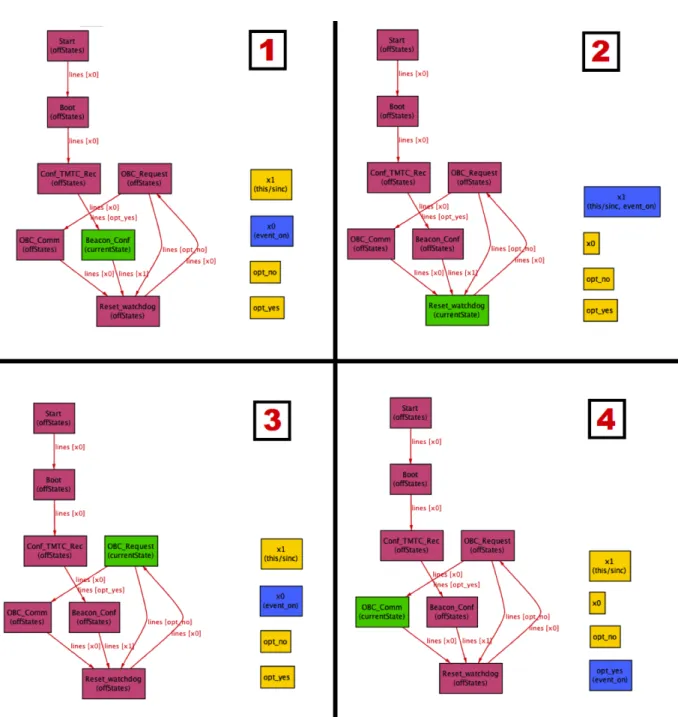
6.5 Software modules alloy . . . 67
6.6 Overlap of Software Modules by Satellite Modules . . . 69
6.7 Receiver, Communication with OBC diagram [ITASAT documentation] . . 70
6.8 Communication with OBC, Interruption Alloy Model . . . 72
6.9 Communication with OBC, Interruption Alloy Model . . . 73
6.10 Three different states (1,2,3) of the Memory . . . 75 xvii
List of Tables
3.1 Mechanical Support for Specification and Analysis Phases of FM . . . 16
3.2 Levels of Formalisation and Scope of Formal Methods Used . . . 20
4.1 Multiplicities in a Binary Relation . . . 25
4.2 Different Types of a Binary Relation, adaptation from FM Classes . . . 25
4.3 Different Logic Styles . . . 27
4.4 Alloy Quantifiers . . . 30
6.1 Alignment between Satellite Modules and Software Modules . . . 68
Chapter 1
Introduction
1.1
Motivation
One of the rewarding and challenging tasks in software development is to know that the systems that are being designed and constructed are high quality products that people can rely on. This becomes more and more important when we talk about embedded critical environments such as transportation networks, aeronautic and airspace control, weapons deployment and activation systems, international banking transactions adjustments, con-trolled chemical and physical environments (e.g., nuclear power plant and particle acceler-ator), among others.
Developers of this type of software have to be sure that there is no possibility of either errors and failures that may cause tragical accidents with human lives being at risk, or bad management of significant amounts of money due to software malfunction. In an effort to find and correct these possible errors, building a perfect software piece (bug free), teams try to document and design a full test strategy, side-by-side with the software evolution plan. This is a possible approach on how the two sides can work side-by-side. Figure 1.1 shows that for every important step made in the development design, there should be a correspondent verification and validation testing process monitoring and following those steps.
Software validation and verification activities check the software against its own re-quirements and specifications. In order to do this there are some guidelines that should be followed. Furthermore, every project must be verified and validated, as far as possible, by someone other than the author.
The steps of the verification progress are:
• checking that every unit meets specified requirements; • ensuring that the process of including an item is safe;
• the effort on verifying and validating an item should be adjusted to the critical level that will be operationally used.
2 CHAPTER 1. INTRODUCTION
Figure 1.1: Verification and Validation Model, adaptation from Jones and Mortensen [1995].
1.2
Problem
Software verification and validation is very important and affects directly the quality of the software; the probability of making errors is higher especially in big projects and where the faults can be propagated easily. Errors that are left behind become more and more hard to find and correct. People are not perfect and do mistakes: a software that has not been verified will increase strongly the probability of operational failure. The objective of this attestation is to reduce software errors to an acceptable level. The effort needed depends upon how critical and how complex the software is [Beizer and Reinhold, 1983].
Further, it has been observed that organizations using just traditional testing methods are restricted to a certain level of quality in terms of safety. This means that a point is reached where major improvements are no longer possible due to the technology used. Even with exhaustive tests on the software produced, these organizations still have some faults and defects they cannot control [Kelly et al., 1992]. In order to fight against them, formal methods techniques were introduced in the project life-cycle. Formal methods are logical (mathematical) techniques, often supported by tools, for developing and analysing software and hardware systems. Mathematical rigour enables users to analyse and verify these models at each of the development phases: requirements engineering, specification, architecture, design, implementation, testing, maintenance, and evolution.
1.3. OBJECTIVE 3 Being aware that there are many issues to be taken into account when considering incorporating formal methods in software development is very important. Many levels of accuracy, as well as a large variety of formal methods depending on the phase of software development, can be adopted. The cost/benefits analysis of the use of formal methods is in fact an important issue, with project management factors as well as technical factors to be considered.
The Brazilian Institute of Aeronautics Technologies (ITA) is building a Satellite, the ITASAT project. In such a complex project in terms of human resources, money invested and financing, a good planning is critical to reduce the costs and to improve the project quality. In order to avoid changes in the project in a later phase, verification and validation must be performed. In fact, those changes might imply extra costs and cause the project to go overbudget, due to the extra labour hours or space equipment changes, that in this situation could mean paying extra thousands for a new processor or for a communication antenna.
1.3
Objective
To address this issues and to improve and facilitate the usage of formal methods in verification and validation of a critical project design, this thesis proposes the creation of a set of guidelines in order to help the user to build a model in a more easy and smooth way. This provides the project manager with an initial overview of the project in a very short period of time, allowing to model the early project phase as well as the more complex final approach. The model can grow as the project grows and gives feedbacks in useful time.
The main focus is to assist the ITASAT work-group in the creation and development of such a critical software aerospace project. We want to define a more linear and organized verification and validation plan to, formally, verify the most critical parts of the project, supported by Alloy models and proceed side-by-side with a formal modelling in several of the project different phases. The work follows a direct line from Architectural Design, Communication Module to Transceiver Code.
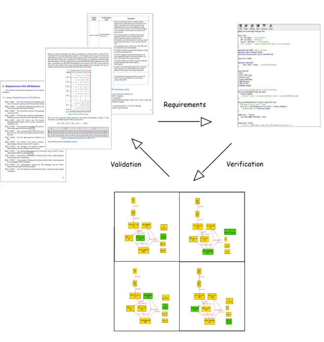
The goal of this project, as shown in Figure 1.2, is to extract the requirements from the documentation, create an Alloy Model that enables formal verification and validate those models again with the former documentation. To help the Alloy Model creation, an automatic model maker tool would be very useful.
We will focus our efforts in the creation of the models and analysing those models in order to find faults with a formal model checker. In this thesis, we assess the current state of the art in Verification and Validation (VV) and the application of Formal Methods (FM) in the software development process, concentrating on their increasing use at the earlier stages of specification and design in critical software projects.
The objective is to study the application of Formal Methods in the development process of ITASAT (satellite of Aeronautical Institute of Technology - ITA). The OBDH (On-Board Data Handling) subsystem will be used as a case study. The work will be divided into three phases: in the first part, guidelines for a formal model are going to be developed with some
4 CHAPTER 1. INTRODUCTION
Figure 1.2: The life-cycle of Validating and Verifying the requirements using Alloy.
extra features, as a support for the creation of a more reliable model to be used with the Verification and Validation methods; then, in second phase, a tool will be created to support the model creation, making use of the pre-stablish rules in the guidelines in phase 1. Finally, in the third phase, a Formal Methods approach with model verification will be made in the different project phases to give a mathematical formalism support in the specification, development and verification of software system, trying to contribute to the reliability and robustness of the design, performing appropriate mathematical analysis.
1.4. CONTRIBUTIONS 5
1.4
Contributions
Due to the complexity of the entire project, that joins together several engineering areas - mechanics, electronics and informatics - the work was based mainly on the documenta-tion. It was not possible to make use of some formal tools, which are used for static code analysis (i.e. BLAST), in the code creation phase owing to deep project alterations at the mechanical and structural level. However, a system architecture model methodology was developed to verify and validate some critical modules against their specifications, restric-tions and requirements. This guidelines can thus be used to help increasing confidence in the correctness of a specification and the related implemented or modified code, and to make it easier to keep the specification and code in sync.
The structural methodology guidelines were defined to help creating the models from the documentation, using the Alloy language and using those models for validating the specification.
Alloy Analyzer proved to be useful to automatically find flaws in the models and help in the verification process of the project’s critical requirements. The ModelMaker tool was designed and created to support in the model creation process. It proved to be very helpful and time saving to build and to initiate the model. Some features were added, such as: cycles verification, limited transition access and checking starvation. This tool makes the process of building and starting checking the requirements much more easy and productive. Thanks to this initial project quick modelling, some errors and flaws were found, and some logistic incompatibilities in the communications modules that could derive into high-cost mechanical modifications were detected, thereby allowing a correction in the embryonic stage of the project.
Although those guidelines were elaborated and directed for a satellite modelling, they can be used to model other systems, to simulate a dynamic modelling and to automatically check the requirements and the overall project design.
1.5
Structure of the Document
The document is structured as follows: Chapter 2 the work that has been made at ITASAT is presented; then, in Chapter 3, we discuss the reasons for testing critical software, showing the effort of two important international aeronautic agencies, the European Space Agency (ESA) and the National Aeronautics and Space Administration (NASA), the first in VV and the other in FM, finalizing with a brief introduction to FM tools and methodologies; in Chapter 4 Alloy language and the Alloy Analyzer tool is briefly described. Chapter 5 ,“Using Alloy”, is divided into two parts: the first describes our guidelines for building an Alloy initial model with extra features, and in the second part the new tool ModelMaker is presented and succinctly described. In Chapter 6, the application of both of the guidelines and of the created tool in some phases of the ITASAT project, is illustrated with several examples. Finally, in Chapter 7, we draw some conclusions about current practice and we outline future work.
Chapter 2
ITASAT
2.1
Introduction
A satellite or human satellite is an object which has been placed into orbit by humans. Several countries build satellites, but just a few have the ability to launch them. Brazil has a launching zone located in Alcˆantara Launch Center (Centro de Lan¸camento de Alcˆantara– CLA), in Maranh˜ao. There are several launching centers in the world but this one has an increased importance due to some special characteristics:
Equator Line Proximity Saves fuel and helps the launchers’s momentum when exiting the Earth;
Vertical and Horizontal Earth Launching It is possible to launch satellites to equa-torial orbits and polar orbits.
Low Demographic Density With such a big center area is possible to have several silos for different rockets.
Stable Clime Raining season well defined and low winds rates make launching a satellite possible almost all year.
With a such special location and characteristics, the Alcˆantara Launch Center became an important piece in the airspace strategy and industry.
The ITASAT project, the first Brazilian university satellite, is a part of the Multi-Year Development Plan and Launching Small Technological Satellites, aimed at promoting and supporting the Brazilian demand for future generations of micro and nano-satellites. The overall coordination of the project is made by the Brazilian Space Agency (AEB), while the Aeronautics Technological Institute (ITA) is responsible for the project execution and the National Institute for Space Research (INPE) provides technical advise, laboratory infrastructure and financial management. ITASAT was designed to work as a weather satellite. There are several applications for space satellites, which, among other functions, are used for:
8 CHAPTER 2. ITASAT Navigation, Tracking and Mapping The use of Global Position System (GPS), for helping in vehicles routes, such as car, boats, planes, etc. Tracking devices are implanted in all kind of objects such mobile phones, cars, black boxes, etc. Thanks to satellites it is possible to access a global map of the Earth.
Communication Satellites can be used for controlling direct communications instead of using the Earth structures.
Military and Security Satellites are constantly scanning and keeping observation on hostile territories around the globe, providing images and data to military command and intelligence agencies.
Science and Discovery Cameras and other scientific instruments can go through space and return information to ground stations with important informations in order to know more about the planets in our solar system and the space itself.
Entertainment Television and radio are nowadays supported by satellites organizations. Meteorology and Geology Satellites also enable us to scan the surface of the Earth for geological research and geological analysis, particularly to predict when an active volcano is about to launch or spot the early warning signs of a developing hurricane. They can monitor atmospheric changes in the Earth’s atmosphere, enabling us to predict and forecast the weather.
Satellites are still very expensive and really difficult to maintain. Abandoned satellites contribute to grow the space debris, making it dangerous for space travels and increasing the danger of damages in shuttles when they try to leave and enter the atmosphere.
The Space Surveillance Network (SSN) has tracked a total of more than 24,500 ob-jects in space, about 20,000 pieces of “space junk” in low-Earth orbit, most of which are discarded bits of spacecraft or debris from collisions in orbit. SSN is now watching about 8,000 objects currently in orbit. A few hundred satellites are currently operational, whereas thousands of unused satellites and satellite fragments orbit the Earth as space debris. The United States Strategic Command is primarily interested in the active satellites, but also tracks space debris which upon re-entry might otherwise be mistaken for incoming missiles.
2.2
ITASAT
With an annual budget of $1.7 million, ITASAT is a micro-satellite for collecting en-vironmental and weather data. This small satellite was designed to be launched as a “piggyback” payload of an primary satellite mission. This options allows the secondary satellite to travel in the same structure, since unification among payloads and launchers enables quick exchanges of payloads and utilization of launch opportunities on short no-tice.
2.2. ITASAT 9 The ITASAT project is a combination of several areas: communication, electronic, me-chanic, computer engineering and science, all of them aiming at airspace projects. The work group is composed approximately of twenty Master degree students, and supervi-sors from INPE and ITA to provide some orientations. It is a high complexity project, since it involves developing a software considering the restrictions of all the project related areas: periodic communication, space reduction, expensive materials, short memory and slow processors, etc.
It is interesting to note that, in the aeronautic and airspace systems, every item included in the system is extremely important and has a vital function in the project. Otherwise, it would not be included due its high cost. Figure 2.1 shows what is involved when planning a satellite mission, and how complex it is. The system is divided in:
Subject The objective of the experience. The objective of ITASAT mission is getting information about the weather.
Orbit and Constellations When sending a satellite to the space it is necessary to know its trajectory and its role in the organization of the other satellites.
Payload, Space Element, Spacecraft Bus The satellite itself with the instruments to get the information and studies from the space.
Launch Element In order to launch a satellite to space is necessary a transporter. In this case, ITASAT is a piggyback satellite and it will use a transporter from a primary satellite.
Ground Element The infrastructure on earth that allows the communication between Earth station and the satellite in the space.
Mission Operation The “intelligence” on Earth is a group of people that is responsible for taking decisions and reacting to the given satellite informations.
Command, Control and Communications Architecture It is vital to plan the sys-tem architecture. That involves all the actions-reactions decisions in communication and define the procedures.
The national investment in the space area, provides a series of missions designed to conduct experiments, develop and test innovative technology of satellites and payloads, and enables the Brazilian space industry in this segment. The first phase of the program was created in 2003 with the participation of the ITA and INPE, to study possible ways of University - Research Institutes - Industry - Government, interaction in implementing such a program, and to study the main technological aspects involved in conducting a mission in the program: satellite subsystems, integration and testing, launch, ground segment, op-eration, management and project documentation. Thus the Project “ITASAT-1 Mission” was the first project-mission of this program.
10 CHAPTER 2. ITASAT
Figure 2.1: Mission Concept, adaptation from Larson/Wertz, Space Mission Analysis and Design Workshop [2012].
Given the novelty of the initiative and its institutional coverage, the project went through several stages before being consolidated. After its creation, various forms of col-laboration and participation of the institutions involved were studied. The type of satellite and mission that would be up to an university satellite was also discussed and ultimately there was an attempt to study various aspects of the development of small satellites (for micro-satellites weighing less than 100kg).
2.3. ARCHITECTURE 11
2.3
Architecture
As Figure 2.2 shows, the satellite mechanical and structural subsystem (MSS) is divided in four main modules: attitude control and data handling (ACDH), electric power (EPS), telemetry and telecommand (TMTC) and the satellite payloads.
ACDH performs on board data handling and attitude control routines. To perform the satellite attitude control, it contains sensors and actuators. The sensors are three solar sensors and a three axis magnetometer that can be used for experimental atti-tude estimation and control algorithm. The actuators are three air coils. The ACDH interacts with the TMTC to manage the communications, receiving and controlling the energy level in the EPS, and ACDH manages the payloads operation.
TMTC subsystem has two transceivers (nominal and redundant). Each transceiver is composed of a receiver, that receives telecommands (TC) from the ground station, and a transmitter, that transmits telemetrics (TM) to the ground station. The receivers are configured in hot-standby redundancy (always listening), and the trans-mitters are configured in cold-standby redundancy (just activated when needed). TMTC module communicates with the main module due to communication modules (CMs) in ACDH.
EPS can store and accumulate energy due to its solar panels. tIs objective is to support the power demands and to warn the main module if the battery reaches a certain low point.
PAYLOAD The satellite payload has four experiments: the digital data collection sys-tem (DCS), an acetone-aluminium heat pipe, an attitude estimator equipment with memories (MEMS), and the inter satellite link equipment (FoX/ISL).
Every module is a vital module, otherwise it would not be part of the satellite. Without the TMTC module, neither the collected data management, nor the reception of commands from the ground station would be possible. Without the EPS, the satellite would not have energy to survive in space. If the payloads cargo failed, the satellite would turn into a simple metal box sending a beep with unnecessary information from the space. If the main control module ACDH was lost, there could not be communication or the information received could not be managed, resulting in a full functional ”body” machine without a ”brain”.
Student teams have to analyse the orbit properties for ground station visibility and related implications on the different satellite subsystems, such as on board data handling, power, telecommunications, attitude determination and control, thermal control and struc-ture.
The selected area in the ITASAT satellite system diagram in Figure 2.2 represents the communication between the On-Board Computer and the communication module and it is an important part of our study.
12 CHAPTER 2. ITASAT
Figure 2.2: Diagram of the ITASAT satellite system
2.4
Attitude Control and Data Handling
The ITASAT project consists of several subsystems, including Attitude Control and Data Handling subsystem (ACDH).
The Attitude Control and Data Handling has two main groups of functions: satellite control and internal communication Attitude and Orbit Control Subsystem (AOCS), and data processing board On-Board Data Handling (OBDH).
There are two types of data to be handled by the satellite on-board computer: they are the housekeeping data and scientific data. Housekeeping data is information about the operation of the satellite; for example: position, temperature, electric current, voltage electrical, connected subsystems state, among others. This information is used by the ground segment to verify the functioning of the subsystems. The scientific data is the information collected by the instruments on board for studies propose; for example, images, data on the effects of radiation. The largest part of the satellite data is scientific.
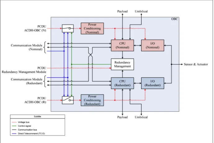
Those several modules are controlled by the On-Board Computer subsystem, Figure 2.3, known as OBC. A 32bit processor resistant to radiation and an operating system that supports the functions performed by the satellite are used. The operating system adopted for the ITASAT is RTEMS (”Real Time Executive Multiprocessing System”).
2.5. CONCLUSION 13
Figure 2.3: OBC Hardware Diagram
2.5
Conclusion
Brazil has a good geographic position for launching satellites and is investing in the space industry and space projects. One of this projects is the ITASAT, that was initially designed to work as a weather information center and for carrying extra payloads.
This Chapter gives an introduction to satellites technology, and the overall ITASAT project and its architecture.
The Brazilian Space Agency coordinates the overall project, while ITA and INPE en-sure project execution, provides technical advise, laboratory infrastructure and financial management. This group is responsible for the complex organization of the overall mission (earth, space and communication).
The satellite architecture is divided into four main sub-systems: attitude control and data handling, telemetry and telecommand, electric power and Payloads.
OBC is an important module that combines and manage all of the other modules inside ACDH.
Chapter 3
V & V in Critical Systems
3.1
Introduction
The first vital step in a high-quality software development processes are requirements engineering [Woodcock et al., 2009]. A perfect software product is built when every step is carefully verified and validated against its specifications and, only then, we advance and transport to the next level. This way, we can be sure that the piece that is going to be used is ”clean” and does not propagate error or failures. As the product development goes through different stages, an analysis is done to ensure that all required specifications are met. Software verification and validation is such model, which helps the system designers and test engineers to confirm that a right product is built in the right way throughout the development process and to improve the quality of the software product.
Verification can mean the act of reviewing, inspecting, testing, checking, auditing, or otherwise establishing and documenting whether items, processes, services or documents are in accordance with the specified requirements [ANSI et al., 1995]: it is the process of making it sure that the software product is developed in the right way. The software should confirm to its predefined specifications.
Validation is confirmation by examination and provision of objective evidence that software specifications conform to user needs and intended uses, and that the particular requirements implemented through software can be consistently fulfilled. Software valida-tion is essentially a design verificavalida-tion funcvalida-tion [CDRH, 2002]. Validavalida-tion is, therefore, linked directly to verification [Jones and Mortensen, 1995]. Validation is the process of finding out if the product being built is right?. That is, whatever software product is being developed, it should do what the user expects it to do.
Validation activities include: technical reviews, walkthroughs and software inspections, checking that if software requirements are traceable to user requirements. Verification activities may include formal proofs to demonstrate logically that software is correct, how-ever, proof techniques are often difficult to justify in non-critical or low-quality software because of the additional effort required above the necessary verification techniques of re-viewing, tracing and testing.
16 CHAPTER 3. V & V IN CRITICAL SYSTEMS
The Verification and Validation processes work side-by-side, but visibly the valida-tion process starts after the verificavalida-tion process ends. Each verificavalida-tion activity (such as requirement specification verification, functional design verification, etc.) has its corre-sponding validation activity (such as functional validation/testing, code validation/testing, system/integration validation, etc.)[Jones and Mortensen, 1995].
Two documents of airspace agencies are presented here. They proved to be very useful as formal methods guides for planning this work. The first is from the European Space Agency (ESA), and describes how to design a well structured Verification and Validation Plan in a critical-software project; the second presents a guidebook from National Aeronau-tics and Space Administration (NASA) and speaks of the importance of formal methods in software engineering and its inclusion in academic centres and specialised teams.
Formal methods have the advantage of focusing more directly on the topic, avoiding the distractions implied by implementation factors. Mechanised tools can be used to support Formal Methods in the specification and analysis phases, Table 3.1.
FM Phase Tool Tool Function Specification Parser Checks syntactic consistence Specification Unparser Translates internal representation into
display and outputs formatted text Specification Type-checker Checks semantic consistency
Analysis Animator, Exhibits behaviour of system modeled simulator by syntactic and semantically
correct specification Analysis Proof checker, Performs proof over syntactical
model checker and semantics correct specification Table 3.1: Mechanical Support for Specification and Analysis Phases of FM
[Kelly et al., 1998]
The application of formal methods is normally divided in three phases:
Stages of the development life cycle A high level verification is made in the project requirements in the project design;
System components The verification is made through an external checking of the mod-ules, black box testing (checking the system output, without knowing its code imple-mentation). i.e. Evaluate how the system reacts with a given input;
System functionality This is the more low level verification, in which the internal func-tionalities of the module are verified.
The application of formal methods, in the first category is the most useful, because its use occurs in the early life cycle stages, given that errors cost more to correct as
3.2. ESA DOCUMENT 17 they proceed undetected through the development process. It gives a first impression of the project and specification. The second category works directly with the system components, this one should be focussed only in the main and critical components due to the complexity of applying verification to a high percentage of the project. The third, ensures that the system component meets its functional specification, moreover, in some cases it is more important to ensure that a component does not exhibit certain negative properties or failures, rather than to prove that it has certain positive properties, including full functionality [Kelly et al., 1998]
3.2
ESA Document
The Guide to Software Verification and Validation [Jones and Mortensen, 1995] is one of the documents produced in a series of guides to software engineering produced in the Board for Software Standardisation and Control (BSSC), of the European Space Agency (ESA). It can work as a support guide in what a Software Verification and Validation Plan should contain. This guide is especially targeted to project managers but also useful to software engineers and software quality assurance staff.
When talking about creating a piece of software, the focus cannot be only creating a program. Developing quality software requires a very careful planning and dedication in every phase of the program life cycle. Verification and validation process is becoming an important and critical solution to achieving the desired objective. Software should be verified during every phase of its life cycle and validated before being transferred [Jones and Mortensen, 1995]. When we speak of critical software, where the process is even more important, this type of software requires greater care.
Figure 1.1 (see page 2) shows a diagram of the work flow of a project’s life-cycle accord-ing to the V model. Software development starts in the top left-hand corner, progresses down the left-hand ’specification’ side to the bottom of the ’V’ and then onwards up the right-hand ’production’ side. The V-formation emphasises the need to verify each stage (left-side) with a verifying phase (right-side), each level of production is verified against its corresponding specification. The development of a product should be a sequential set of tasks to produce a high quality piece of software. For that, a combination between development and testing is made, trying to validate each stage in order to advance to the next phase. In particular the:
Software Required Definition must be verified with respect to the User Required Definition
Architectural Design must be verified with respect to the Software Required Defi-nition
Detailed Design must be verified with respect to the Architectural Design
With these verification activities, the relation between the requirements, specifications and real software produced is shown. Demonstration that a product meets its specification
18 CHAPTER 3. V & V IN CRITICAL SYSTEMS should be a mechanical activity driven by the specification.
Verification of Detailed Design is efficient for demonstrating conformance to functional requirements (e.g. to validate that the system has a function it is only necessary to exercise the function). In contrast, demonstration that a product contains no defects that prevent it from meeting its specification requires expert knowledge of what the system must do, and the technology the system uses. This expertise is needed if the non-functional requirements (e.g. those for reliability) are to be met. Skill and ingenuity are needed to show up defects. The product will show more confidence to the users, if rigorous testing and verification have been made before release.
3.3
NASA Document
The NASA Guidebook from Kelly et al. [1998]is an important document that is going to support the work in terms of formal methods. It describes tools and strategies to follow to be successful on using formal methods on this same thematic of critical software.
It should be noted that there are many issues to be taken into account when considering incorporating formal methods in software development. There are many different levels of formality or rigour that can be adopted and a variety of formal methods can be used to address many different subtasks in a software development project. We have to be aware of the costs benefits of using this type of mathematics methods, it is also a matter of administrative and management factors that should be take into account. A wide variety of tools and features are available and have to be taken into consideration due to costs associated with its use. Two guidebooks are being presented: one, which addresses of management and technical support using formal methods and the other, addressing the application of the formal methods in specification and verification of software systems. It also discuss techniques,requirements and strategies for verifying high-level designs.
3.3.1
NASA Guidebook I
This Guidebook from Kelly et al. [1998] considers technical and administrative matters for the use of formal methods included in the project. It aims to include the use of formal methods in the development of critical systems, creating high-quality systems at an economically practicable level. More particularly, this volume of the guidebook is:
• written for people that are considering the use of formal methods on their project and its implications, such as project owners and managers;
• describe the advantages and the importance of using formal specifications;
• a good guideline for people that intend to plan and implement formal methods in a project. It also has tools descriptions, case studies and modifications to the levels of rigor for applying formal methods.
3.3. NASA DOCUMENT 19
3.3.2
NASA Guidebook II
This Guidebook Kelly [1997] presents technical issues involved in applying formal meth-ods to specify and analytically verify software systems. Practical techniques and strategies for verifying requirements, and high-level designs for software intensive systems are dis-cussed. The focus is on illustrating the growing practicality of applying formal methods for enhancing the quality of aerospace and avionics applications. This work is also a product of the NASA Software Program and was cooperatively developed by a three-center NASA team formed by the Jet Propulsion Laboratory, Johnson Space Centre, and Langley Re-search Centre. More particularly, volume II of the guidebook is designed to:
• help the transition of formal methods from experimental use into practical application for critical software requirements and design within NASA;
• provide guidance for the novice practitioner;
• discuss technical issues involved in applying these techniques to aerospace and avion-ics software systems.
The Volume II also includes an illustrated example on a NASA application: the Sim-plified Aid, for EVA Rescue (SAFER). This example can be very useful in applying for-mal methods in the test plan software subsystem OBDH (On-Board Data Handling) of ITASAT. SAFER is a system for free-floating astronaut propulsion that is intended for use on Space Shuttle missions, as well as during Space Station construction and operation. It is a small, self-contained, backpack propulsion system enabling free-flying mobility for a crew-member engaged in extravehicular activity (EVA) that has evolved as a streamlined version of NASA’s earlier Manned Manoeuvring Unit (MMU).
3.3.3
Levels of Formalisation
The levels of formalisation, as seen in Table 3.2, are defined in order to increase effort. The distinction between them, reflects the extent to which each technique is both math-ematically well defined and supported by mechanized tools, yielding systematic analyses and reproducible results [Kelly, 1997]. The first uses notations and concepts derived from logic and discrete mathematics, to improve the requirements. The second uses a formalise specification language supported by tools such as syntax checkers and system simulators. This level of formality uses models and abstract data types. The third is a rigorous seman-tic formal specification language and correspondingly formal proofs methods that supports mechanization in this level and high specialization using theorem provers, proof checking ,and model checking and model finder.
20 CHAPTER 3. V & V IN CRITICAL SYSTEMS Levels of Formalization Scope of the FM Use
1. Mathematical concepts and notations, Life cycle phases: information analysis (and if), no mechanization all/selected
2. Formalized specification languages, System components: some mechanized support all/selected 3. Formal specification languages, System functionality: comprehensive environment, including full/selected automated proof checker/theorem prover
Table 3.2: Levels of Formalisation and Scope of Formal Methods Used [Kelly et al., 1998]
3.4
Formal Approach
This Section presents different checking levels and different methods for applying for-mal methods. Several tools are considered for the different approaches. Finally, a brief introduction is made about the chosen approach and language.
3.4.1
Verification Methodology
After the system is properly formally specified, this specification can be used as a guide for developing a concrete and more reliable piece of software. It is possible to generate a model in order to find inconsistencies during the design process (i.e., realized typically in software, but also potentially in hardware). This formal specification can be made in two different ways:
operational semantics a concrete system result can be compared (which itself should be executable or able to be simulated) with the behaviour of the specification. This methodology is common called as “black-box”, the verification is made by simulat-ing the input and checksimulat-ing the output of the modules, without knowsimulat-ing the inside mechanism and how it is done;
axiomatic semantics the preconditions and postconditions of the specification may be-come assertions in the executable code. This is a more intrinsic verification. The verification is made on the specific functionality and make sure that if the precondi-tions are ensure the output is valid and respect all the requirements restricprecondi-tions. Software specification can be supported using formal methods. It is possible to write specific statements to build a guide model and to make it construct the product. A speci-fication is a technical contract between programmer and client to provide them both with knowledge of the use cases, each describing a subcomponent of the system. Complex software systems require careful organization in the architectural structure of their compo-nents: a model of the system that suppresses implementation detail, allowing the architect
3.4. FORMAL APPROACH 21 to concentrate on the analyses and decisions that are most crucial to structuring the system to satisfy its requirements [Allen and Garlan 1992; van Lamsweerde 2003].
Verification and Validation methodology is useful to make sure that the required specifi-cations are being followed and fulfilled. This helps detect and correct mistakes and failures in an earlier state of the product. An error corrected in the beginning is much easy and low-cost to correct than in future phases.
Formal methods rigour and correctness helps to analyse and verify these models. A wide automated toolbox is available and can be used for checking completeness, traceability, verifiability, and reusability, and for supporting requirements evolution, diverse viewpoints, and inconsistency management. In this way, we make sure that what we tested is correct because we have a logical-mathematical base prove supporting it.
At implementation level, formal methods are used in code verification. It is possible to document the code with mathematical assertions and annotations, which are relations that hold between the program variables and the initial input values, in order to control the checking of the theorem or why the theorem fails to hold. Some tools can automatically generate code from a formal model.
3.4.2
Formal Approach
In order to verify if the system is working like it is suppose to, we can use the previous specification to check the system. This can be made by Human-directed proof or Automated proof. The first approach tries to prove the correctness of a program using mathematical proofs, handwritten (or typeset) using natural language, using a level of informality common to such proofs. Second approach produces proofs of correctness of such systems by automated means. The automated techniques fall into two general categories: Automated Theorem Proving and Model Checkers, that are specified using a Specification Language.
Specification Languages used to formally describe a problem using mathematical con-cepts. Some examples are: a formal specification notation Z; a declarative language for describing rules that apply to Unified Modeling Language (UML) models, Ob-ject Constraint Language (OCL); a language used to obOb-ject-oriented and concurrent systems modeling, Vienna Development Method-Specification Language (VDM-SL); and Alloy, an expressive logic based on the notion of relations formal language. Automated Theorem Proving in which a tool attempts to prove the properties defined
in the specification. They generate formulas in a mathematical language, encouraging more reliance by the user on the system’s automatic aspects.
(e.g. ACL2 [Kaufmann and Moore, 1997])
Model Checking given a model of a system, the tool checks automatically whether this model checks against a specification, see (BLAST [Kolb et al., 2010], SLAM and is Specification Language SLAM-SL [Ball et al., 2011] and Alloy Analyzer and its specification language Alloy).
22 CHAPTER 3. V & V IN CRITICAL SYSTEMS e.g. Alloy contrary to other specification languages, the first approach to Alloy is ”smooth”. Alloy is a very simple but expressive logic based on the notion of relations. It can be used to create a first sketch of a model in a easier way. When the initial model is ready, it can be improved incrementally. Alloy was influenced by modelling languages (such as the object models of OMT and UML). Alloy’s tool, the Alloy Analyzer, is a solver that takes the constraints of a model and finds structures that satisfy them. It can be used both to explore the model by generating sample structures, or to check properties of the model by generating counterexamples. Structures are displayed graphically, and their appearance can be customized for the domain at hand. The Alloy Analyser works by reduction to a boolean satisfiability problem (SAT), where it establishes if the variables of a given Boolean formula can be assigned in such a way as to make the formula evaluate to TRUE. Several languages, such as Z, B, Event-B, UML and VDM-sl, are trying or are already translated to Alloy to make use of the its Model “Finder”, the Alloy Analyzer [Mikhailov and Butler, 2002, Malik et al., 2010, Matos and Marques-Silva, 2008, Anastasakis et al., 2010, Lausdahl, 2013].
3.5
Conclusion
The ESA document is a very important standard reports of verification and validation that can be usefully to create a verification and validation plan and to use and follow some guidelines for introducing a formal methods approach to support the development of a critical software project.
Both Nasa guidebooks are very important because they can be used as supplementary survey reading material and guideline for formal methods experts, government, industry, and academia. However, the second guidebook, shows a more practical component ap-proach to an important case study (SAFER manoeuvring device) of a formal methods application, which has been specified and analyse used the PVS specification language and iterative proof checker, used already in another NASA projects.
Nowadays, a extensive collection of tools allows us to automatically exploit many of the mathematics advantages in a formal model or formal specification. Despite their practical use in software development still being quite expensive, they can be seen as a good in-vestment. Discovering system failures and error early on system, lead to a great reduction in future corrections. Alloy is an expressive logic based formal language that can be use to create models working side-by-by with Alloy Analyzer in order to verify and find the models. Having analyzed several options, Alloy and Alloy Analyzer were chosen for their differentiated lightweight properties in creating and verifying a formal model, and the its importance and utility in nowadays projects and research.
Chapter 4
Alloy
4.1
Introduction
Abstraction is the key to the creation of a good model for a real problem. It is important to model a system in an early stage to get a more general and concise idea of what the project really is and is going to be. Alloy was chosen for this project due to its ability to define and generate a initial model which becomes more robust and complex, evolving as the project grows. It generates a model that can be used to simulate structures and behaviours with a small part of the project description, thus having an advantage in comparison with other similar tools that need a full description, requirements or test cases. Alloy uses relational logic, defining atoms, functions, predicates and facts, those are the Alloy units. Alloy Analyzer can then use the model to check the validity of logical expressions, in an interactive way, by running and checking commands. Alloy was used because of its combination of singular characteristics:
Models and Micromodels With just a few lines it is possible to create and visualize a model and have a better perspective of the system that is being checked. Compared with other formal languages it is easy to learn and easy to use and, at the same time, very quick finding faults and counterexamples that invalidate some assertions. Analysable Models Alloy was created and joined with a formal model checker, the Alloy
Analyzer. The Alloy Analyzer is an automatic tool which allows a better visualization of simulation models without any kind of external help in terms of inputs or tests cases. It can also check properties; if a property does not hold, a counterexample is created and we can have a very helpful visual analysis.
Declarative Models A system state is defined by using a declarative approach that de-fines not only the state of the system, but also the actions and the transition to the next state, using predicates, invariants, properties and constraints.
Structural Models It is possible to analyse the complexity of a software system in terms of sequence of events complexity and structural complexity. There are some tools
24 CHAPTER 4. ALLOY capable of checking and analysing the complexity of those systems. Most of them analyse sequences of events, while Alloy is part of a selected group of tools that can also analyse structures complexity.
The use of micromodels is very important since the user can choose only the criti-cal and risky areas of the full project, the core module, the most expensive modules to maintain, etc. This attention to the more important areas in a system results in a more reliable control on complex, hard-to-check projects. Alloy is a powerful formal method tool that combines first-order logic and relational calculus using a language with a syntax for structured specifications; moreover, it is capable of performing analysis with bounded, exhaustive search for counterexamples using SAT [Sheeran et al., 2000], the satisfiability problem solver.
Alloy = Logic + Language + Analysis
4.2
Atoms and Relations
Alloy uses atoms and relations to create the models and to describe the specifications. An atom is the smallest unit in the model that does not change over time and it also does not contain any extra information. Therefore, an atom is the singular, primitive entity, and it is indivisible, immutable and uninterpreted. To build a model, the atoms are linked by relations, which are strongly typed. Relations, sets, scalars are all the same in the Alloy language.
A relation is a set of tuples that contains atoms or sets of atoms in order to map and create more complex typed structures. In the case of a tuple with two sets, a so-called binary relation, the left part can be seen as domain and the right side as range.
The example below shows the definition (signature) of an atom Instant which contains a scalar (i.e. a singleton unary relation) identifier to store the instant id; also has two unary relations: currentOnState indicating the current state, and offStates to store the states that are not being used at the moment: in this cases, a set of atoms and not just one.
In Table 4.1 a more complete explanation is given for the relations multiplicities. The last relation is a multirelation line, and defines the path of the system with a set of tuples State → Event → State. Multirelations (relations with arity of 3 or more) are used to represent higher-order (i.e., nested) relations.
sig Instant{
identifier: one Id
currentOnState : set State, offStates : set State,
4.2. ATOMS AND RELATIONS 25
line : State -> Event -> State }
A relation can be described in a more abstract way without any obligation of including all the atoms connections for both sides. In order to create different relations with different multiplicities some keywords are used. In Table 4.1, the m is substituted with one of the four words: set, one, some or lone, each one with a different meaning and utility. If no word is used, it is assumed that it is one.
A m → m B
set any number 0 .. ∞ one exactly one 1 some at least one 1 .. ∞
lone at most one 0 - 1
Table 4.1: Multiplicities in a Binary Relation
Table 4.2 shows the different types of binary relations: a function can be represented using the word one in the right side of the relation (range), the abstraction relation is also extremely useful in order to model a data structure, such as an array of [A], which can be transformed into a relation in Alloy, Z + A,(some Z have one correspondent element in A).
A lone → B A some → B A → lone B A some → B left unique left total right unique right total
injective partial functional surjective A lone → some B A → one B A some → lone B
concretization function abstraction A lone → one B A some → one B
injection surjection
A one → one B bijection
Table 4.2: Different Types of a Binary Relation, adaptation from FM Classes Depending on the system which is being modelled, the abstract model can be formalized using this high relations, or the more usual functions such as injectives, surjectives or one-to-one bijectives functions. In the code below, a bijective definition and a function similar to a map to extract the image of A can be seen.
26 CHAPTER 4. ALLOY
sig Pair{ mapList : State one -> one State}
fact defValues{ Pair.mapList = (A -> B) + (C -> D) } fun giveRange[a : State]: State { Pair.mapList[a] }
First, the signature Pair is defined with the mapList relation one-to-one. Next, two pairs are attributed to the maplist relation with a fact which means that is always a fact that this two pairs (A,B) and (C,D) are in the list. Therefore, it is possible to access B by navigate through mapList in giveRange(A) function. The result is the state B; note that maplist[a] = a.maplist.
4.3
Alloy Logic
Alloy tries to represent problems using an extended version of first-order logic that can be called relational first-order logic. This logic combines first-order logic with rela-tional calculus. The addiction of relarela-tional operators is important in order to express more complex descriptions as transitive closure and reflexive transitive closure. Alloy translates first-order logic with a finite scope into propositional logic. In order to automate the solv-ing problem process it tries to reduce and perform few transformations in first-order logic working as an input for satisfiability automated solvers.
Alloy allows the user to use several options when using logic to specify a model, making it even more tempting for different types of users. The example below shows several ways to express the “injective property”:
4.3. ALLOY LOGIC 27
Navigation expression style: all n : Name, d, d’ : Address |
n → d in address and n → d’ in address implies d = d’
Relational calculus style: n → d in address and n → d’ in address
Predicate calculus style: no ∼address.address - iden
Table 4.3: Different Logic Styles
4.3.1
Propositional Logic
Propositional logic is isomorphic to zeroth-order logic and very similar to first-order logic without the quantifiers ( ∀ and ∃). It uses primitive symbols (atomic formulas, placeholders, proposition letters, or variables) and operator symbols that create relations between formulas. It is common used and an important logic that interprets the proposi-tions, in this case, into two possible values: True or False. SAT tries to satisfy a formula giving a boolean formula of the primitive symbols in use to evaluate to True. With that boolean formula it can now generate a model in which the variables are generated to vali-date the model.
An example of a truth table used in propositional logic:
Conversation with 3 friends:
a) I just go to the party if Einstein and Ergos go. b) I just go to the party if Einstein or Ergos go.
c) Because i like both, i just go out if they (Einstein and Ergos) have/take the same decision.
p = Einstein goes to the party q = Ergos goes to the party
p q a) p ∧ q b) p ∨ q c) p ↔ q
⇒ T T T T T ⇐
T F F T F
F T F T F
28 CHAPTER 4. ALLOY So the best solution is when both Einstein and Ergos decide to go out and the three friends have a nice night all together.
4.3.2
First-Order Logic
First-order logic, also known as predicate logic, is a formal system that uses constants, variables, functions and predicates to describe a system. The domain of this variables could be very large, and therefore not so easy to reduce to a satisfiability problem (SAT). An introduction of how first-order logic works:
Definition of Statements:
S1 = “Just one message can turn off the system” Definition of Predicates:
Message(x) ≡ x is a message.
TurnOff(x) ≡ x turns the system off. Logic:
∃x [Message(x) ∧ TurnOff(x) ∧ ∀y [(Message(y) ∧ ¬(x=y)) =⇒ ¬ TurnOff(y)]]
“For a given message X, that turns off the system and for all messages Y that are not X, message y cannot turn off the system”
This property describes the previous statement S1.
In order to reduce first-order logic to a problem that can be decidable by a SAT solver, it is necessary to apply some inferences rules. Among them we cite as an example the Universal Elimination or Existential Introduction: adapting the forall X to a more re-strict domain of (x1, x2,..,xn). Universal Elimination reduces the universal domain to a more restrict and small domain, eliminating the infinite scope (for all, ∀); Existential Introduction gives a “name” to a variable that exists in the formula to make the propo-sition formula always true. The quantifiers elimination is done in order to calculate the solution with a more practical scope.
4.4
Alloy Language
The Alloy formal specification language can be considered more light and easier to use than other languages for the same purpose such as Z [Jackson, 1995] or Vienna Development Method-Specification Language (VDM-SL) [Bera, 1988]. The most basic element in Alloy is the atom that can be defined by sig atom{}. An atom can have several relations inside it.
4.4. ALLOY LANGUAGE 29 These Alloy structures can be very similar to Java in terms of objects inheritance. Different kinds of states often have a certain amount of characteristics in common with each other. In the example below, the commands: BinaryCommand, SynchronousCommand, and MessageCommand, all share the characteristics of an abstract Command (current state, binary attribute or string id). Yet each also defines additional features that make them different: Binary command can send a extra bit to the system, the Synchronous command have two objects to be synchronise and Message command have a string that contains the message.
abstract sig Command{
currentState: one State, active: one Bool,
id: one String }
abstract sig routineCommand extends Command{}
sig BinaryCommand, SynchronousCommand extends Command{} sig MessageCommand extends Command{}
one sig UniqueCommand extends Command{}
This can be used for choosing a direction in a system path, i.e. yes or no, messageType1 or messageType2. An abstract state is a state that is declared abstract, it may or may not include abstract relations. Abstract states cannot be instantiated, but they can be subclassed. The keyword one is used to defined that the atom is unique in the model. i.e. # UniqueCommand > 1, (the cardinality of a unique command is greater than 1) is always false.
4.4.1
Operators and Quantifiers
In Alloy everything is a relation, relations can be joined with operators in order to create a more complex relation. There are three types of operators: set operators, relational operators and logical operators.
Set operators include the usual operations such as intersection (&), union (+) or difference (-). The ’=’ is used to compare if two sets are the same. The keyword in checks if a set is part of another. For example, ”a in b“ and ”b in a“ is the same as ”a = b“.
Relational operators include operators such as join(.), transpose(˜), transitive closure(ˆ), reflexive transitive closure (∗), and product (→). The join operator works as a nav-igation operator, for example:
30 CHAPTER 4. ALLOY if: p = (A -> B) (p defines a relation A to B) q = B then: p.q = A
(the domain A is returned, because a navigation is made from B to A in the [A,B] set relation.)
The transpose ˜r of a relation r is its mirror image, reversing the order of the mapping. The transitive closure ˆr of a binary relation r is the smallest relation that contains r and is transitive. The reflexive, transitive closure *r is the smallest relation that contains r and is both reflexive and transitive. i.e., it is similar to ˆr but includes a mapping from every atom to itself. The product of two relations is similar to the join, but the intermediate atoms are not dropped. The result is the relation containing the concatenation of every tuple in the first relation with every tuple in the second relation [Crane et al., 2003].
Logical operators includes the operators that are used in formulas. The operators are similar to the set operators: conjunction (&&), disjunction(||), implication(⇒), biimplication(⇔) and the negation(!). Quantifiers are also used in formulas that contain free variables. Alloy has five types of quantifiers as illustrated in Table 4.4.
Quantifier Meaning
all x : e | F universal, F is true for every x in e some x : e | F existential, F is true for some x in e
no x : e | F F is true for no x in e sole x : e | F F is true for at most one x in e
one x : e | F F is true exactly one x in e Table 4.4: Alloy Quantifiers
4.4.2
Functions, Facts, Assertions and Predicates
Functions Function definitions can be seen as formulas. The functions receive some arguments and return the set of the results that match with the written definition.
4.4. ALLOY LANGUAGE 31
sig Pair{
pair: Left -> Right }
fun theOtherSIde[p : Pair]: set Left { p.pair.Right
}
The objective of this function is to get the Left side of the Pair relation. It receives the object Pair, and returns a set of Right, it does a navigation from Right in the Pair.pair relation.
Facts are similar to signatures but are used to define a model “constant” attribute that cannot change over time and as to be always satisfied. They can be written in a sepa-rate paragraph or be a part of a signature. In the example below the ’#list <= 4 fact is written under the A signature, and it works such that the cardinality of this.list has to be less or equal than 4. Meanwhile fact1, because is written in a different paragraph, does not have the association of the signature, for this reason is necessary to add the A in the beginning of the expression.
The final model is the conjunction of all facts and invariants. As is shown is Fig-ure 4.1, the Alloy Analyzer creates a model following the model description. In this example, the model must have a state A with connections to three states (because of fact1), plus two extra states resulting for the run command, explained in 4.4.3, requiring the model to have five states.
sig State{ }
one sig A{
list : set State }{
# list <= 4 }
![Figure 1.1: Verification and Validation Model, adaptation from Jones and Mortensen [1995].](https://thumb-eu.123doks.com/thumbv2/123dok_br/17798974.840675/22.892.153.788.173.544/figure-verification-validation-model-adaptation-jones-mortensen.webp)
![Figure 2.1: Mission Concept, adaptation from Larson/Wertz, Space Mission Analysis and Design Workshop [2012].](https://thumb-eu.123doks.com/thumbv2/123dok_br/17798974.840675/30.892.190.739.146.820/figure-mission-concept-adaptation-larson-mission-analysis-workshop.webp)

![Table 3.2: Levels of Formalisation and Scope of Formal Methods Used [Kelly et al., 1998]](https://thumb-eu.123doks.com/thumbv2/123dok_br/17798974.840675/40.892.147.754.153.335/table-levels-formalisation-scope-formal-methods-used-kelly.webp)