This content has been downloaded from IOPscience. Please scroll down to see the full text.
Download details:
IP Address: 188.184.3.52
This content was downloaded on 02/12/2013 at 09:29
Please note that terms and conditions apply.
Mechanical construction and installation of the ATLAS tile calorimeter
View the table of contents for this issue, or go to the journal homepage for more 2013 JINST 8 T11001
(http://iopscience.iop.org/1748-0221/8/11/T11001)
2013 JINST 8 T11001
PUBLISHED BYIOP PUBLISHING FORSISSAMEDIALAB
RECEIVED: June 21, 2013 ACCEPTED: October 16, 2013
PUBLISHED: November 4, 2013
TECHNICAL REPORT
Mechanical construction and installation of the
ATLAS tile calorimeter
The ATLAS Tile Calorimeter Community
J. Abdallah,aP. Adragna,b C. Alexa,c R. Alves,d P. Amaral,e, f A. Ananiev,g
K. Anderson,hX. Andresen,e, f A. Antonaki,i V. Batusov,j P. Bednar,k A. Behrens,e
E. Bergeaas,l C. Biscarat,mO. Blanch,nG. Blanchot,nJ. Blocki,e,abC. Bohm,l
V. Boldea,cF. Bosi,bM. Bosman,n C. Bromberg,o B. Brunel,e J. Budagov,j
D. Calder ´on.a D. Calvet,mC. Cardeira,gT. Carli,e J. Carvalho,dM. Cascella,b
M.V. Castillo,a J. Costello,aM. Cavalli-Sforza,nV. Cavasinni,bA.S. Cerqueira,p
C. Clement,e,lM. Cobal,e F. Cogswell,qS. Constantinescu,c D. Costanzo,b
P. Da Silva,p M. Davidf T. Davidek,r,eJ. Dawson,s,†K. De,t T. Del Prete,b
B. Di Girolamo,e S. Dita,cJ. Dolejsi,rZ. Dolezal,r A. Dotti,bR. Downing,qG. Drake,s
I. Efthymiopoulos,e D. Errede,qS. Errede,q A. Farbin,h,eD. Fassouliotis,iE. Feng,h
A. Fenyuk,uC. Ferdi,mB.C. Ferreira,pA. Ferrer,aJ. Ferrer,n V. Flaminio,bJ. Flix,n
P. Francavilla,b E. Fullana,aV. Garde,mJ.C. Gaydee K. Gellerstedt,l
V. Giakoumopoulou,iV. Giangiobbe,bO. Gildemeister,e V. Gilewsky,v N. Giokaris,i
N. Gollub,eA. Gomes,f V. Gonzalez,aJ. Gouveia,g P. Grenier,e,mP. Gris,m
J. Grudzinski,sV. Guarino,sC. Guicheney,mA. Gupta,hH. Hakobyan,w M. Haney,q S. Hellman,l A. Henriques,eE. Higon,aN. Hill,sS. Holmgren,l I. Hruska,x
M. Hurwitz,hJ. Huston,oI. Jen-La Plante,hK. Jon-And,l T. Junk,qA. Karyukhin,u
J. Khubua,y, j J. Klereborn,l S. Kopikov,uI. Korolkov,nP. Krivkova,rY. Kulchitsky,v, j
Y. Kurochkin,v P. Kuzhir,zV. Lapin,u,†C. Lasseure T. LeCompte,sR. Lefevre,m
R. Leitner,r J. Li,t,†M. Lyablin,j H. Lim,sM. Lokajicek,x Y. Lomakin,j,†P. Lourtie,g
L. Lovas,kA. Lupi,bC. Maidantchik,p A. Maio,f S. Maliukov,j A. Manousakis,i
C. Marques,f F. Marroquim,pF. Martin,e,mE. Mazzoni,bD.Mergelkuhl,e F. Merritt,h
A. Miagkov,u R. Miller,oI. Minashvili,j L. Miralles,nG. Montarou,mS. Nemecek,x
M. Nessi,e I. Nikitine,uL. Nodulman,sO. Norniella,n T. Nyman,eA. Onofre,aa
M. Oreglia,hB. Palan,x D. Pallin,mD. Pantea,cA. Pereira,d J. Pilcher,h J. Pina,f
2013 JINST 8 T11001
J. Proudfoot,s,1 M. Ramalho,g M. Ramstedt,l L. Raposeiro,gJ. Reis,gR. Richards,o
C. Roda,bV. Romanov,j L. Rose-Dulcina,e P. Rosnet,mP. Roy,mA. Ruiz,a
V. Rumiantsau,z,† N. Russakovich,j J. Sa da Costa,gO. Salto,nB. Salvachua,a
E. Sanchis,aH. Sanders,hC. Santoni,mJ. Santos,f J.G. Saraiva,f F. Sarri,b
L.-P. Says,mG. Schlager,eJ. Schlereth,sJ.M Seixas,pB. Selld `en,l N. Shalanda,u
A. Shchelchkov,,j P. Shevtsov,zM. Shochet,hJ. Silva,f V. Simaitis,qM. Simonyan,w
A. Sissakian,j,†J. Sjoelin,l F. Skrzecz,sC. Solans,aA. Solodkov,uO. Solovianov,u
J. Sorokina,,j M. Sosebee,t F. Spano,e,bP. Speckmeyer,e R. Stanek,sE. Starchenko,u
P. Starovoitov,zM. Suk,rI. Sykora,k F. Tang,hP. Tas,rR. Teuscher,hS. Tokar,k
N. Topilin,j J. Torres,a D. Underwood,sG. Usai,bV. Utkin,j A. Valero,a S. Valkar,r
J.A. Valls,a A. Vartapetian,t F. Vazeille,mC. Vellidis,i F. Ventura,g I. Vichou,q
I. Vivarelli,bM. Volpi,n A. White,t K. Wood,sA. Zaitsev,u A. Zenin,uT. Zenis,k
Z. Zenonos,b S. Zenzh and B. Zilkak
†Deceased
aIFIC, Centro Mixto Universidad de Valencia-CSIC, E46100 Burjassot, Valencia, Spain bPisa University and INFN, Pisa, Italy
cInstitute of Atomic Physics, Bucharest, Romania dLIP and FCTUC University of Coimbra, Portugal eCERN, Geneva, Switzerland
fLIP and FCUL University of Lisbon, Portugal gLIP and IDMEC-IST, Lisbon, Portugal
hUniversity of Chicago, Chicago, Illinois, U.S.A. iUniversity of Athens, Athens, Greece
jJINR, Dubna, Russia
kComenius University, Bratislava, Slovakia lStockholm University, Stockholm, Sweden
mLPC Clermont-Ferrand, Universit´e Blaise Pascal, Clermont-Ferrand, France
nInstitut de Fisica d’Altes Energies, Universitat Aut`onoma de Barcelona, Barcelona, Spain oMichigan State University, East Lansing, Michigan, U.S.A.
pCOPPE/EE/UFRJ, Rio de Janeiro, Brazil
qUniversity of Illinois, Urbana-Champaign, Illinois, U.S.A. rCharles University in Prague, Prague, Czech Republic sArgonne National Laboratory, Argonne, Illinois, U.S.A. tUniversity of Texas at Arlington, Arlington, Texas, U.S.A. uInstitute for High Energy Physics, Protvino, Russia
vInstitute of Physics, National Academy of Sciences, Minsk, Belarus wYerevan Physics Institute, Yerevan, Armenia
xInstitute of Physics, Academy of Sciences of the Czech Republic, Prague, Czech Republic yHEPI, Tbilisi State University, Tbilisi, Georgia
zNational Centre of Particles and High Energy Physics, Minsk, Belarus
2013 JINST 8 T11001
aaLIP and Univ. Cat´olica Figueira da Foz, Portugal
abHenryk Niewodniczanski Institute of Nuclear Physics, Polish Academy of Sciences, Krakow
E-mail:[email protected]
ABSTRACT: This paper summarises the mechanical construction and installation of the Tile Calorimeter for the ATLAS experiment at the Large Hadron Collider in CERN, Switzerland. The Tile Calorimeter is a sampling calorimeter using scintillator as the sensitive detector and steel as the absorber and covers the central region of the ATLAS experiment up to pseudorapidities ±1.7. The mechanical construction of the Tile Calorimeter occurred over a period of about 10 years be-ginning in 1995 with the completion of the Technical Design Report and ending in 2006 with the installation of the final module in the ATLAS cavern. During this period approximately 2600 met-ric tons of steel were transformed into a laminated structure to form the absorber of the sampling calorimeter. Following instrumentation and testing, which is described elsewhere, the modules were installed in the ATLAS cavern with a remarkable accuracy for a structure of this size and weight.
2013 JINST 8 T11001
Contents 1 Introduction 1 2 Design overview 2 3 Submodule construction 9 4 Module production 12 4.1 Module construction 134.2 Girder ring insertion 15
4.3 Installation of fiducial marks 15
5 Calorimeter installation 16
1 Introduction
The ATLAS Tile Calorimeter (TileCal) [1] is the barrel hadronic calorimeter of the ATLAS
exper-iment at the CERN Large Hadron Collider [2]. Calorimeters in a general purpose detector, such
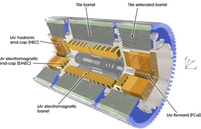
as ATLAS, have the function of providing energy and position measurements of electrons, pho-tons, τ−leptons and jets. An important requirement from the need to infer neutrinos from missing energy is that the calorimeter have a maximum geometrical coverage and a minimum level of uninstrumented volume and physical gaps associated with its mechanical construction. A key ad-ditional function of TileCal is to provide sufficient depth of absorber to wholly contain the hadronic showers from particles emitted in proton-proton collisions and thereby enable the identification of penetrating muons by tracking detectors surrounding the calorimeters.
The ATLAS calorimeter system is shown in figure1. TileCal is a sampling calorimeter using
steel as the absorber structure and scintillator as the active medium. The scintillator is located in pockets in the steel structure and is read out using wavelength-shifting fibers that couple the scintillation light to photomultiplier tubes which are located inside the outer support girders of the calorimeter structure. In addition to its role as a detector for high energy particles, the TileCal provides the direct support of the liquid argon electromagnetic calorimeter in the barrel region, and the liquid argon electromagnetic and hadronic calorimeters in the endcap region. Through these, it indirectly supports the inner tracking system and beam pipe. The steel absorber, and in particular the support girders, provide the flux return for the magnetic field from the central solenoid. Finally, the end surfaces of the barrel calorimeter are used to mount services, power supplies and readout crates for the inner tracking systems and the liquid argon barrel electromagnetic calorimeter.
The remainder of this paper is organised as follows. In section2we review the main elements
of the TileCal design. In sections3and4 we describe the mechanical assembly of the different
subcomponents of the calorimeter. In section5we present the installation and final geometry of
2013 JINST 8 T11001
Figure 1. The calorimeter system in the ATLAS experiment at the Large Hadron Collider.
2 Design overview
The detailed design of TileCal is described in detail in the ATLAS Tile Calorimeter Technical
Design Report [1]. A brief summary is given below.
TileCal is constructed in three sections, one barrel and two extended barrel calorimeters, each comprising 64 units (termed modules), which are assembled on each other to form cylinders as
shown in figure1. A barrel module weighs 20020 kg and an extended barrel module weighs 9600 kg
for a total weight for the entire calorimeter of approximately 2600 metric tons. The mechanical structure has a nominal outer diameter of 8460 mm and an inner diameter of 4576 mm. A bar-rel (extended barbar-rel) module has a length of 5640 mm (2900 mm), excluding extensions (fingers) used to contain and protect services for the calorimeter electronics. The calorimeter itself is self-supporting and rests on support saddles placed in the lower regions of the structure as discussed later. The instrumented region of the calorimeter has a radial length of 1.64 m, and contributes 7.4 hadronic interaction lengths for particles emitted at 90 degrees to the beam line. A key design constraint is to have a minimum gap between modules and the fabrication and assembly tolerances provide for a design gap of 1.5 mm. Additionally, the design contains a significant level of inte-gration between the mechanical structure, the scintillator tiles and their optical readout, and the electronics readout and photomultipliers used to measure the light signals from the wavelength-shifting fibres.
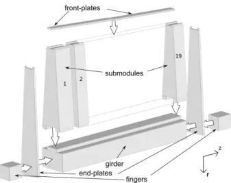
A cartoon illustrating the key elements of a module is shown in figure 2. The girder is the
outer structural support element of the module. It is a precision structure to which the calorimeter absorber is bolted. The calorimeter structure is formed of submodules. Each standard submodule has a length along the girder of 293.2 mm and weighs 865 kg. Eight standard submodules and two customised submodules are used to construct an extended barrel module, while 18 standard submodules and one customised submodule are used to construct a barrel module. A frontplate is welded in a channel at the inner radius to complete the inner structural support element of the module. Endplates are bolted to the girder and welded to the frontplate at the inner radius.
2013 JINST 8 T11001
Figure 2. Cartoon showing the principal components of a barrel module.
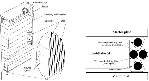
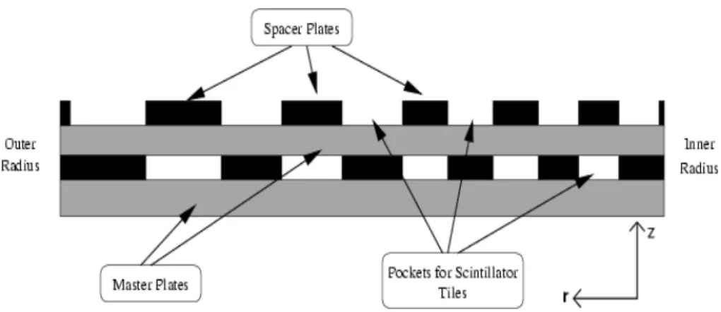
The principal features of a module are shown in figure3. The structure is a glued and welded
steel lamination of full-length plates (master plates) which run radially outward from the beam line. These have short plates (spacer plates) interleaved along their length to form pockets into which the active elements of the calorimeter, the scintillator tiles, are inserted. The spacer plates are set back from the edge of the master plate outer envelope by 2.8 mm to provide a slot in which the readout fibers are inserted. The design includes a progressive increase in the radial length of the spacer plates as one moves from inner to outer radius. This allows the calorimeter to meet its performance specification while minimising the piece count and thereby handling costs. The scintillator tiles are read out by wavelength-shifting fibers which are inserted in channels located between each of
the pairs of full-length plates as indicated in figure3. As a result, no additional absorber volume is
compromised to accommodate the fiber readout and in addition the fibers themselves are protected from mechanical damage by being enclosed on three sides by the steel structure. A plastic chan-nel is used to contain the fibers and provide a cost-effective approach for what would otherwise have been a labor intensive operation. A detailed description of module instrumentation can be
found in [3].
The master plate, shown in figure 4, is the principal component of the calorimeter absorber
structure. Alternating sets of spacer plates are interleaved between master plates to form the slots in which the scintillator tiles are placed, as discussed below. Both the master plates and the spacer plates were fabricated to high precision by die stamping. The slots at either end of the master plate as well as the overall envelope of the plate are the design elements which define the module envelope. In addition, the master plate has 22 precisely located holes through which the tubes
containing a calibration source are inserted along the entire length of the structure (see figure3).
Custom-designed spring pins are inserted in these holes to mechanically fasten and align the spacer plates to master plates. Through appropriate sizing of the outer diameter and inner bore of these pins, the pins also provide the precise alignment of the calibration tubes with the absorber and scintillator structure. The spacer plate setback of 2.8 mm defines the channel in which the readout
2013 JINST 8 T11001
Figure 3. A schematic of the integration between the module absorber structure and the optical components, the view is radially inwards towards the beam line: (left) The sampling structure of the Tile Calorimeter showing the pockets in the steel laminations in which tiles of scintillator are inserted and the location of calibration source tubes which pass through the structure at each depth segment; (right) The integration of the absorber with the scintillator and fiber readout components.
Figure 4. The principal absorber is formed using 5 mm thick steel plates, the master plate shown here in radial profile from outer radius (left side of plate) to the inner radius (right side of plate). The pairs of tabs at the outer and inner radius of the plate form keys which are used to align the plate during construction. Also shown are the envelopes of one set of spacer plates used to form the pockets in which the scintillator tiles are placed.
The outer structural support of the module is the girder. This is a precision, machined and welded steel structure incorporating a key which defines the alignment of submodules to the girder. Shims between adjacent modules form the bearing connection and connecting plates fastened to the girder at the outer radius through shims, bolts and pins provide the module-to-module mechanical connection. In addition, the support girder provides the magnetic flux return for the central solenoid and internally houses the photomultipliers and front-end readout electronics for the calorimeter as
2013 JINST 8 T11001
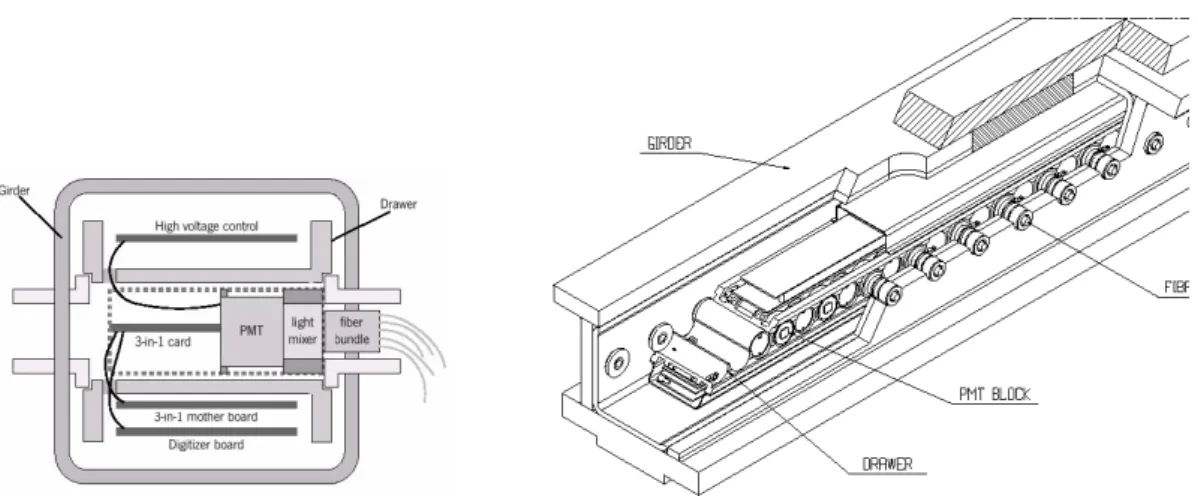
Figure 5. (left) The cross section of the drawer inside the module support girder, with an example of the girder ring to drawer interface on the left hand side of the drawer and an example of the fiber bundle insertion into the girder ring on the right hand side of the drawer; (right) A schematic of the electronics drawer inside the girder volume showing the interface required for extraction and servicing of the calorimeter readout electronics.
precision alignment between the photomultipliers mounted in an electronics box (drawer) inside the girder to the wavelength-shifting fibers bringing light from the scintillator tiles. To provide for periodic access for maintenance, the electronics box must be removable. The solution adopted was to locate the photomultipliers and readout electronics in precision aligned drawers which can be
extracted when necessary from the end of the girder, see figure5(right).
The key mechanical elements in the drawer/girder interface are the girder rings, which are installed during module construction. The drawer slides on these rings which are glued with high precision into the girder plates to control both the position along the length of the girder as well as the distance between the internal surface of the ring and that of the drawer. The typical preci-sion is 0.3 mm along the length of the girder and 0.1 mm between the light-mixer in front of the photomultiplier window and the wavelength-shifting fiber bundle.
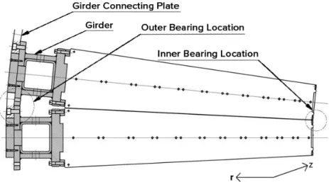
The interface between two modules is shown in figure6 which shows the bearing locations
at the inner and outer radii, the bolted connection between submodules and the support girder described below, and the bolted connection between modules at the outer radius of the girder. Steel shims are glued to the girder and on the surface formed by the edges of the master plates. For the shims laid on the master plates, each shim spanned a submodule width and was extended a distance radially so that the total bearing area of the shim was large enough to insure that the yield stress in compression of the shim and master plates was not exceeded under all possible load conditions.
Adjustments in the thickness of these shims control the gap between modules and such ad-justments were later used during calorimeter assembly to control its overall geometry. It should be noted that the girder width at the interface to the submodule matches the channel in which the fibers are routed so that there is a direct path for the readout fibers into the outer cavity of the girder.
The low voltage power supplies, cooling and readout cables enter the drawer at the end of the girder. These are all contained in extensions of the girder (called fingers) which provide shielding from the return magnetic field as well as physical protection for cables and connectors. The fingers
2013 JINST 8 T11001
Figure 6. The gap between calorimeter modules showing the bearing locations at the inner and outer radii, thereby allowing the readout fibers to pass into the girder volume for coupling to the photomultiplier tubes. The circled sections indicate the load bearing locations at the inner radius of the modules and at the outer radius of the girder. Also shown is the bolted connecting plate.
can be seen in figure2; there are two fingers on barrel modules and one finger for each extended
barrel module. In the regions of the barrel cryostat supports, short fingers are required.
The region between the barrel and extended barrel calorimeters (see figure2) is designed to
maximise the calorimeter coverage while providing space for cables, electronics crates and services from the ATLAS inner detector. To meet this goal, there are a number of locations in the extended barrel where the innermost submodule (in z) requires modification. Three types of special submod-ule were required; a simple plate in the most limited case and two cases in which the calorimeter coverage at the inner radius of the calorimeter is reduced. There are 16 such special modules in
each extended barrel calorimeter. More details may be found in [1].
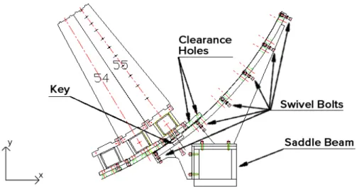
Support saddles distributed along the length of the barrel and extended barrel calorimeters transfer the calorimeter load to the main ATLAS rails. The interface between the saddles and the
calorimeter structure is illustrated in figure7. The modules in the interface region rest on swivel
bolts mounted to the saddle plates. A precision machined keyway in the saddle plate is mated to a precision key machined in the customised module support girder in module number 55, as shown
in figure7, to provide stability to the structure integrated by the barrel (endcap) and the saddles.
The saddle itself is bolted to the saddle beam through which hydraulic blocking jacks transfer the
load to the ATLAS main rails as indicated in figure8. There are four such pairs of saddles along
the length of the barrel calorimeter and two along the length of each extended barrel calorimeter. The cryostat containing the ATLAS barrel electromagnetic calorimeter is supported by four plates which are bolted to the saddles and which transfer the load of the cryostat radially to the
ATLAS main rails (the plates on one side of the barrel calorimeter can be seen in figure8). To
minimise the thickness of these plates while insuring sufficient resistance to buckling, the plates are bolted to the calorimeter structure using high strength rods which pass through the calorimeter, replacing source tubes in these locations. The ATLAS electromagnetic endcap calorimeter is
2013 JINST 8 T11001
Figure 7. The interface between the calorimeter modules and saddle supports. Shown in this figure is the special module whose girder has a machined key which mates with the machined keyway in the support plate, the locations of swivel bolts which transfer the radial load from the calorimeter to the support plate and the saddle beam which transfers the calorimeter load vertically to the ATLAS main rails.
Figure 8. Schematic of the support saddle used to transfer the weight of the Tile Calorimeter to the ATLAS main rail systems. A mirror symmetric saddle supports the cylinder on the opposite rail.
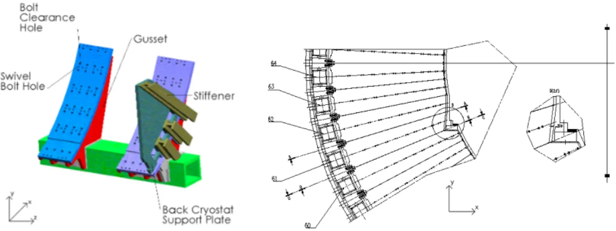
this support: the back cryostat support plate which carries the majority of the weight of the elec-tromagnetic endcap calorimeter and transfers it directly to the ATLAS main rails; jacks located at the inner radius of the TileCal extended barrel calorimeter provide the innermost support as well as vertical adjustment. To provide space for these jacks, the first three submodules in these locations are cut to the necessary geometry and steel plates welded across the cut master plates. Also shown
in figure9is the saddle support plate. The calorimeter sits on swivel bolts inserted in this plate as
2013 JINST 8 T11001
Figure 9. (left) Schematic of one of the pairs of saddles used to support the extended barrel calorimeter; (right) The geometry of the inner support of the end cap cryostat.
Many man years of engineering analysis were carried out to insure the adequacy of the tile
calorimeter structural design and were the subject of extensive engineering review [4–11]. The
de-tails of these calculations are beyond the scope this paper. Globally, Eurocode [12] was employed
and where possible analytical calculations were compared to those obtained by finite element mod-eling. In general 2-dimensional finite element models were used. However, in some critical regions, such as the saddles and cryostat supports, 3-dimensional models were also used. Based on the re-sults of these calculations, for the most sensitive connections (for example welding of the inner radius plate) technician certification and 100% non-destructive inspection were employed during construction. Destructive testing of test pieces was used where engineering criteria did not fall into
a standard protocol [13–15]. One such test was of the bolted connection between the submodule
and the support girder, and was used to determine the maximum allowed stress both in the mount-ing bolts and in the threads cut in the girder steel. This test was also used to establish an empirical measure of the rigidity of the submodule and its connection to the girder for use in subsequent finite element analysis of the calorimeter structure as a whole.
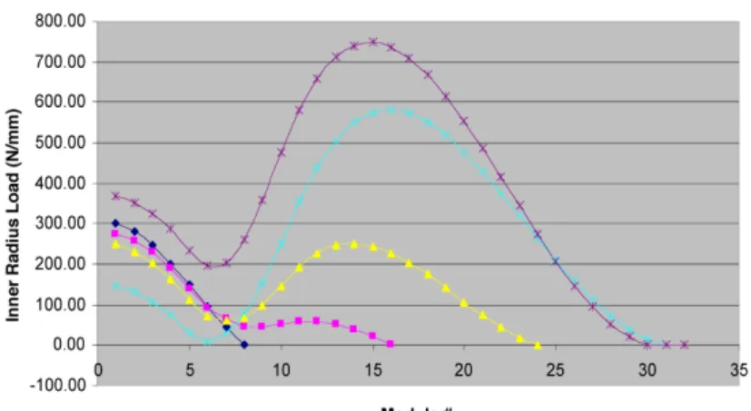
The loading conditions in this design vary throughout the structure. An example of this is
shown in figure10which shows the forces at the inner radius bearing surface of the calorimeter as
a function of the position of the module and of the number of modules in the assembled cylinder. It also shows that at the top of the cylinder (module 32) the load at this interface is zero. These forces were used to determine the minimum area required for the shims at the inner radius of the structure. The forces at the outer radius of the calorimeter (the link plates) show even greater variation than those at the inner radius. Above the saddles the interfaces between modules are in compression, while in the lower section between the saddles they are tension (i.e. the modules want to pull apart). In this case the calculations were used to establish the number and diameter of pins needed to carry this shear force.
Seismic forces were evaluated using the methodology given in Eurocode and an assumed lateral acceleration of 0.15g. Blocks between the saddles and the calorimeters prevent any relative movement along the beam line in this situation. An additional consideration which results in
non-2013 JINST 8 T11001
Figure 10. Calculated force at the inner radius bearing surface of the module-to-module interface as a function of module position in the calorimeter and as a function of the number of modules assembled. Module number 1 is located at the bottom of the cylinder and module 32 is located at the top of the cylinder. The support saddle key is located at module 6 in this figure.
static forces arises during installation when the barrel calorimeter is moved from its assembly location below the cavern access shaft to the interaction point (a distance of about 12 m), or during routine movements of an extended barrel calorimeter for detector maintenance. Guide brackets, attached to the saddles, have been designed to accommodate the maximum non-uniform loading which would occur if one of the two hydraulic cylinders were to fail and the calorimeter moved using only a single cylinder from one rail.
3 Submodule construction
Submodules were constructed at ten institutions (Argonne National Laboratory, the University of Chicago, the University of Illinois, and the University of Texas Arlington in the U.S.A., at the Institut de Fisica d’Altes Energies, and the University of Valencia in Spain, at Pisa University Italy, at Charles University in Prague, Czech Republic and at JINR Dubna and IHEP Protvino in Russia). Assembly tooling was designed to insure uniformity in submodule construction at all sites. This tooling was constructed at each assembly site and qualified prior to beginning mass production. In addition, a common procurement was made for major components such as the master and spacer plates to insure uniformity and minimise cost per piece.
Submodule construction began with the rolling and cutting of steel sheets, 5 mm thick for master plates and 4.05 mm thick for spacer plates with a thickness specification of ±0.05 mm and
±0.04 mm respectively [16]. To achieve the specification of +0/ − 0.1 mm on the outer envelope
of the master plates, as demanded by the specification for the design gap between modules, a
precision die was used for their fabrication [17, 18]. As the stamping die could produce the full
plate geometry in a single pass (holes, keys and envelope), this proved to be an extremely cost-effective manufacturing approach. Die stamping was also used to produce the spacer plates, again
2013 JINST 8 T11001
Figure 11. Cartoon of the basic unit of the calorimeter absorber structure: the full period. This comprises two master plates and two alternating sets of spacer plates stacked such that the voids between master plates form the slots into which the scintillator tiles are to be inserted.
control program was applied during production. In the case of the raw steel sheets, a primary control was applied during rolling to insure the thickness specification. Periodically, steel sheets were sampled and tested to insure low residual stresses as required for the subsequent plate cutting. Gauge plates were designed for use during plate stamping and used to test 1 master plate in 30 as a way of insuring that the stamping die continued to meet specification. In addition, 1 master plate in 600 was measured on a 3-D computer controlled measuring machine at appropriate control points which included the plate width at several locations, and the locations and dimensions of the keys and hole locations. Similar quality assurance protocols were applied for spacer plate production. All remaining components were either conventional procurements or fabricated at the collaborating institutions.
The fundamental absorber unit of the calorimeter structure is formed by the lamination of two
master plates and two (half) sets of spacer plates as shown in figure 11. A submodule is built
up by alternating a master plate with layers of spacer plates which are glued and pinned together and aligned on a precision, standardised stacking fixture. The fixture is comprised of thick steel bottom and top plates together with precision aligned blocks into which the matching keys on the master plates are engaged. A standard two-part structural adhesive was used (Araldite AW 106 and hardener HV953U). After approximately 24 hours, once the glue had cured and prior to removal from the stacking fixtures, two mounting bars were welded to the submodule master plates.
The role of the glue is crucial in the design, providing compensation for the thickness tol-erances of the stacked plates (64 plates are stacked together to build a standard submodule) and contributing additional mechanical strength to the structure. The position of the glue deposition and volume of glue was controlled to give a glue surface area of sufficient shear strength. This deposition was done by a variety of ways ranging from a semi-automatic gluing machine to man-ual deposition using a glue gun and template. The glue line thickness was controlled using thin paper shims and glass microspheres. The mechanical connection via steel spring pins insured the geometrical positioning of the spacer plates relative to the master plates. The tubes used for the
cesium calibration system [20] pass through these spring pins, and thereby align the cesium
2013 JINST 8 T11001
Figure 12. (left) One layer of spacer plates being fastened to the master plate below using spring pins and structural glue; (right) A submodule being assembled on the stacking fixture, the keys at either end precisely align the master plates.
figure12: spacer plates fastened to master plates to form a half-period, and a submodule assembly
on the stacking fixture being prepared for glue curing.
Submodule construction was subject to a detailed quality control plan, which was developed during design and submodule prototyping, to insure uniform production throughout the ten sub-module construction sites. The quality control protocols included careful tracking of glue depo-sition quantities and curing time, inspection of the welding of the mounting bars, and a series of measurements of module flatness, stack height and envelope. The quality control data were pub-lished on web pages maintained at each construction site and regularly monitored to insure that the lessons learned at one site could be rapidly communicated to all sites. The principal dimensional control was on the height of the submodule stack as good maintenance of this height was essen-tial to insure that all submodules could be successfully mounted on the module support girder. A representative example of the submodule stack height for the submodules constructed at one of the
construction sites is shown in figure13. In general, the submodule followed a football shape as a
result of weld shrinkage causing the submodule height to be lower than nominal at the inner radius
and higher than nominal near the center of the submodule. However, as is seen in figure13, this
effect was quite reproducible and largely within the height specification of +0.3 mm and −1.5 mm relative to nominal. The distribution of the maximum stack height deviation from nominal for all
submodules constructed is shown in figure14. The majority of submodules fall within the required
envelope. The small number of submodules whose height exceeded 0.6 mm from nominal were identified with pallets of raw sheets whose thickness exceeded the design thickness specification. A small number of custom submodules with heights of −1.0 to −1.5 mm relative to the nominal height were constructed and mounted adjacent to these submodules during module construction.
Submodule construction concluded with the application of a thin layer of protective paint and a subsequent final quality control check to insure that paint build-up in the slots would not impede insertion of scintillator tiles or the fiber channels. More details on submodule construction and
2013 JINST 8 T11001
-2 -1.5 -1 -0.5 0 0.5 1 Height deviation (mm) Submodule Submodule Stack Heightmax. dev. min. dev.
Figure 13. Stack height monitor data for a typical submodule production series at one of the submodule construction sites. 0 100 200 300 400 500 600 -2 -1 .8 -1 .6 -1 .4 -1 .2 -1 -0 .8 -0 .6 -0 .4 -0 .2 0 0.2 0.4 0.6 0.8 1 1.2 1.4 1.6 1.8 2 No . of S ubmodules
Max. Dev. from Nominal (mm) Submodule Stack Height
Figure 14. Stack height maximum deviation from nominal for all submodules constructed. 4 Module production
Module construction was carried out at three collaborating institutions (Argonne National Labo-ratory in the U.S.A., JINR Dubna in Russia, and the Institut de Fisica d’Altes Energies in Spain) where appropriate facilities for handling and storage were available. Each of these institutions was assigned the task of construction of one of the major sections of the full calorimeter: Barrel (LB), Extended Barrel C (EBC), and Extended Barrel A (EBA). Other than its physical size, the TileCal
calorimeter module is a simple object. As shown in figure 2, three components form the basic
module absorber structure: the structural support girder, the front plate and the submodules. In addition, external endplates are used to provide for mounting of services on the end surface of the calorimeter and plastic inserts (girder rings) glued into the steel support the readout electronics and position the fiber bundles. Extensions (fingers) are bolted to the module to contain power supplies for the readout electronics. Finally, precision reference marks (fiducial marks) are attached to the ends of the module for use in calorimeter assembly.
2013 JINST 8 T11001
PD H(i) H(0) H(n) laser L LÕA(0) A(i) A(n)
Laser beam
Y
U1 U2
U3
U4
Figure 15. Laser system used to align and control the location of submodules along the length of a barrel module. This tooling was also adapted to control the module envelopes for both barrel and extended barrel modules for the determination of the shim thicknesses to be used during calorimeter assembly.
There are two critical constraints pertaining to module assembly: the overall module envelope which was required to lie within +0.6 mm of the nominal envelope, and the girder ring positioning such that the electronics drawer alignment to them was precisely maintained while still allowing the drawer freedom to move in and out of the girder volume. Tooling was developed to insure that these constraints would be met. The overall construction approach closely followed that which was developed in the prototype phase of the project and which is described in the Tile Calorimeter
TDR [1]. Further details on the use of this tooling can be found in [21,23–25].
In the remainder of this section we present details on the three key phases of module construc-tion: module mechanical construction, girder ring installation, and installation of fiducial marks.
4.1 Module construction
Module mechanical construction followed the same sequence at all three assembly locations. First the support girder was leveled and bolted to the assembly base. A right angle, or precision level, was then used to align submodules vertically on the girder. Shims at the bolted interface between submodules and the girder insure that the girder key is never in contact with the submodule and also correct the submodule position and alignment, bringing it inside the overall module envelope. The alignment of submodules at the inner radius was accomplished by different techniques at the different locations. In the case of the barrel assembly, a laser was used together with the fixed endplates at either end of the assembly base to establish the alignment reference system, as shown
schematically in figure15. A quadrant-style photodetector is illuminated by the laser beam, and
the position of the beam relative to nominal is determined by centering the response of the four quadrants of the detector using a bridge circuit. In the case of the extended barrel modules, which are half the length of the barrel module, a simpler approach was used. In one case a precision electronic level was used to align vertically the center of the submodule, as defined by the holes for the source tubes. In the second case, an alignment fixture was placed in the inner radius key of the submodule and an optical transit used to set the submodule vertical and centered on the centerline of the girder (as established by a reference hole placed in the girder during fabrication.)
Mounting endplates at the end of the module was similar to mounting submodules, except that these plates are undercut by 0.5 mm relative to the module envelope and therefore great precision was not required for this operation. Following a basic envelope check, the front plate was welded into the inner key, joining together all submodules as well as the endplate.
2013 JINST 8 T11001
-0.4 -0.2 0.0 0.2 0.4 0.6 0 20 40 Saleve Sidedistribution of distances to the best fit plane
Tol eranc e mm N Mean = 0.00 mm Sigma = 0.13mm
Figure 16. Example photogrammetric measurement of a barrel module: distribution of offset distances relative to the best fit plane.
Quality control protocols were developed during the prototype development and used during module construction. These included two important checks on the mechanical integrity of the module:
1. A cross-check of the preload on submodule mounting bolts, which is a particular concern in the extended barrel assembly where different preloads are used in different regions of the calorimeter (both for different modules dependent on their planned position in the assembled calorimeter and for different submodules on any given module.)
2. 100% non-destructive inspection of the weld of the front plate (to insure continuity of the bearing surface at the inner radius in the final assembly)
Two sets of measurements were made of the module geometrical envelope. For the barrel the laser system described above was the primary system used to control the envelope of all modules during
module assembly [23]. Additionally, several barrel modules have been measured by a
photogram-metric system at CERN. This technique provides a wholly independent way of controlling the mod-ule envelope from that provided by the laser-based approach, and could provide rapid and accurate
results independently of any requirements on the physical location of the module. Figure16shows
the distribution of offsets to the best fit plane of one face of one of the modules measured, showing
that for this module the measured aplanarity is less than 0.4 mm. Figure17shows these offsets as
a function of location showing no systematic effects. Four barrel modules were measured using both the laser-based and photogrammetric techniques; the two sets of measurements agreed within
±70µm. Further details of this comparative analysis are given in [26]. In the case of the extended
barrel modules a 2 m precision straight edge was used in conjunction with feeler gauges to measure the out-of-plane deviation of absorber plates along the length of the module. The deviations along the length of the module, or from outer to inner radius, reflected the different types of systematic bias associated with the different approaches used for submodule mounting. For all modules, the
2013 JINST 8 T11001
Dist to plane (mm) Side SALEVE Point 1 Point 38 Level 1 Level 4 Z (m) Y (m)Figure 17. Example photogrammetric measurement of a barrel module: offset distances relative to best fit plane as a function of location on the barrel module.
maximum deviation from nominal was less than 0.5 mm for all points measured. After instrumen-tation, the module surfaces were covered by a sheet of black tedlar and aluminum tape used to cover mounting holes inside the girder to provide light sealing. During calorimeter final assembly as a further precaution, a bead of RTV silicone paste was placed at the outer edges all round the module.
4.2 Girder ring insertion
An ingenious approach was developed to decouple the very high precision needed for the inter-face to bring scintillation light signals to the photomultiplier tubes from the precision required to
position the holes in the girder through which the fibers enter. Figure18(right) shows a close-up
of the penetrations in the girder. They are large holes in the structure and positioning them to the tolerance required by the optical light coupling to the photomultiplier tube would have resulted in a prohibitive fabrication cost for the girder. Instead of this, the approach used was to glue plastic
transition pieces (girder rings) into these holes. The tool shown in figure18(left) was used to
posi-tion and precisely locate the inner secposi-tion of the girder rings. The electronics drawer rides on, and
is located relative to these rings (as seen in figure5) such that the optical coupling is geometrically
controlled to a precision of 0.3 mm. The outer sections of the rings mate with the inner sections and the full assembly is glued into the girder with foam seals at inner and outer surfaces insuring light sealing and minimal leakage of glue onto the girder surfaces. The girder rings themselves are the element which establishes the optical alignment path for fibers during instrumentation.
4.3 Installation of fiducial marks
The final task associated with module assembly was to attach fiducial marks to the module end-plates and fingers, for use during calorimeter assembly. These are small mounting fixtures, which are located to high precision and which can accept different types of inserts and survey pins to allow either optical or ruler-based measurements of the position to be made. In addition to stan-dard targets for optical surveying and photogrammetry, a custom tool was constructed to use the hole in which these devices are inserted as a locating point for a precision ruler in order to make
2013 JINST 8 T11001
Figure 18. (left) The pneumatic tool used to insert and locate the inner pieces of girder rings for gluing resting on top of a girder ready to have girder rings installed; (right) The outer girder rings following gluing, the black rings are the foam rings used to seal the plastic inserts to the girder surface.
rapid measurements of the distances between modules. Custom tooling was used to position these fixtures at three radial locations (close to the inner and outer radius of the module, and at a location roughly in the middle of a module radially at a location which would not be obscured by the flanges of the cryostats). The tooling establishes the reference for these fiducial marks from the z position of the end of the support girder, and establishes the centre line for fiducial mark installation us-ing a precision level and the outer edges of the girder bearus-ing surfaces. The typical precision is 0.3 mm in all three coordinates. More details of this aspect of the module assembly can be found
in reference [23].
5 Calorimeter installation
The calorimeter is designed as a self-supporting structure formed by the modules which bear on each other at the inner and outer radius. The calorimeter is supported on simple supports by the saddles and as a result of this support condition, the module interfaces at the outer radius are in tension below the saddles and are in compression above the saddles. The position of the supports has been chosen such that the system is stable once 18 modules have been mounted (i.e. just at the top of the saddles). The overall system is designed so that no load is carried across the two modules at the top of the cylinder. Radially, the Tile Calorimeter is constrained by the clearance envelope to the barrel and endcap cryostats (inwards) and by the radial clearance envelope to the inner chambers of the muon system (outwards). The global radial envelope was set at +5 mm outward and −10 mm inward. The positioning of the calorimeters along the beam line is less critical as adjustment is possible. As the system is initially unstable, the calorimeter assembly was begun on an external support frame until the point at which the support saddles were mounted and the load transferred to
them, see figure19. This assembly frame was also designed to serve as the fixture on which a
pre-assembled section of calorimeter could be lowered into the ATLAS cavern. In the case of the barrel calorimeter, this comprised 8 modules, and for the extended barrel calorimeters this comprised 16 modules together with the support saddles. By this means, the critical and time-consuming task of inserting the shear pins, required to carry the tension load between modules below the saddles, was carried out primarily during the surface assembly. These pins are 33 mm in diameter, are 80 mm in
2013 JINST 8 T11001
Figure 19. The assembly cradle, here shown for the case of 16 modules mounted. The cartoon shows the cradle beam with intermediate pads on which jacks are mounted to carry the module loads during assembly. The outer blocks indicate the external supports used during surface assembly to support the cradle and in the cavern to provide an independent support of the calorimeter prior to the load transfer to the saddles and ATLAS main rails.
length and must be match-drilled through the girder connecting plates, penetrating approximately 30 mm into the girder. The surface installation of these pins provided relatively convenient access to the calorimeter structure which greatly facilitated this task. Modules were mounted until 18 modules were assembled and the system was gravitationally stable. At this point the calorimeter load was transfered from the jacks below the assembly frame through the saddles to the ATLAS main rails. The assembly fixture was then dis-assembled and removed to the surface.
An important point in the assembly is the installation of the barrel (endcap) liquid argon calorimeters. In the case of the extended barrel calorimeters, due to the geometry of the inner support, the cryostat was installed after 24 modules had been mounted and the load then trans-ferred to the ATLAS rails through the rear support plate and the inner radius jacks. In the case of the barrel calorimeter the barrel cryostat was installed after 30 modules were mounted, but the load was not transferred to its supports until all modules had been mounted. Following installation of the electromagnetic calorimeters, modules were mounted until the barrel (extended barrel) calorimeter was complete. During this phase the calorimeter geometry was measured and adjusted by shims to maintain the calorimeter within the geometrical specification.
The control of the radial geometry of the cylinder was carried out by adjusting the shim thick-nesses used, module-by-module. The scheme used to determine the nominal shim thickness as a function of shim position along the length of a module used the same approach as was used
for barrel module assembly. A laser measurement system as shown schematically in figure15is
referenced to the module endplates, which themselves are referenced to the center of the support girder during module construction. The photodetector is scanned along the bearing surface of the girder and along the module at the radius at which the inner radius shims are glued. The data were recorded and used to determine the shim thicknesses to be used for the interface between each module pair. This is the nominal shim thickness. It was used for all modules mounted during the pre-assembly and was adjusted for subsequent modules during cavern assembly as discussed be-low. Thus, using simple tooling, the shim thicknesses along the length of the module were adjusted to insure that the calorimeter met its radial specification and also the planarity specification for the
2013 JINST 8 T11001
surface formed by the endplates of +2 mm relative to nominal. This was a particular issue for the
barrel calorimeter due to its length of almost 6 m. More detail can be found in [23].
Due to the self-supporting feature of the design of the Tile Calorimeter, and the size of the structure, the assembly of the calorimeters began with a full surface assembly to establish the
va-lidity of the planned assembly approach prior to installation in the cavern [24]. Geometrical surveys
were carried out at each major stage in the assembly procedure to provide data for subsequent use in performing the assembly process in the cavern. These measurements included detailed surveys of individual components used in the assembly (the assembly cradle and the support saddles) and of the cradle, saddles and the mounted modules which were measured periodically until the full calorimeter had been constructed. The survey results from the pre-assembly were used to deter-mine the best fit calorimeter axis and to anticipate the position of the liquid argon calorimeters for use in the cavern assembly.
Several measurement techniques were used to monitor the geometry of the calorimeter during pre-assembly, all of which used the fiducial marks described above as the reference points. The techniques comprised: a custom precision ruler used to measure the chord length between opposite modules; optical survey of the positions of the fiducial marks, caliper measurements between fidu-cial marks on adjacent modules, and photogrammetric measurements of the partially assembled or entire calorimeter. Following disassembly of the structure, the shims at the bearing surfaces were removed and measured by micrometer. Several key observations were made using the data obtained from the surface assemblies:
1. The precision required for the shim thickness is of order 50 µm.
2. Shim deformation at the inner radius is large and dependent on the exact load conditions (e.g. number of modules in the assembly, and before or after loading of the cryostat in the case of the extended barrel calorimeter).
3. Due to the changes in shim thickness as they deform, the calorimeter shape also changes dramatically as a function of the load conditions.
4. Due to the lever arm of the calorimeter, small changes in the gap between modules at the inner radius have a large effect on the geometry of the calorimeter (and in particular on the adjustments needed to insure that the calorimeter is closed).
A full surface assembly was completed for the barrel calorimeter (excluding the load of the barrel cryostat). In the case of the two extended barrel calorimeters a full surface assembly of one was completed (also excluding the load of the endcap cryostat load), while for the second extended barrel, the surface assembly was carried out up to the point at which a load equivalent to that of the endcap cryostat could be installed.
Figure20shows the envelope deviation from nominal for the C-side of the barrel calorimeter
measured following surface assembly (the calorimeter ends are identified as either A- or C- de-pending on their location in the cavern). Similar deviations, both in magnitude and location were measured for the A-side of the calorimeter. The calorimeter is slightly flattened, somewhat more at the top than at the bottom, and has bulged outward at the sides. The maximum outward de-viation is approximately 5.5 mm and the maximum inward dede-viation is approximately −4.5 mm.
2013 JINST 8 T11001
Figure 20. Surface assembly survey, deviation from the best fit center of the calorimeter as determined by a global optimization algorithm for fiducial mark positions on the C-side of the barrel calorimeter. The three sets of points are for the fiducial marks at the inner, middle and outer radius of the module as discussed in the text.
The calorimeter is almost entirely within its design envelope and both sides of the calorimeter are essentially identical in shape indicating that no twisting occurred during the assembly process.
The data taken during the surface assembly of the calorimeters were used to validate and establish the parameters used in two independent numerical models which were subsequently used to monitor the calorimeter geometries during final assembly in the ATLAS cavern. The models were used to adjust the shim thicknesses for the expected shim deformation relative to nominal shim thickness, to compensate for the additional shim deformation resulting from the cryostat loading, to correct for errors made during the surface assemblies and to determine corrections as needed during the final stages of the calorimeter assembly to insure space for installation of the final module.
The final assembly in the cavern benefited enormously from the surface assembly experi-ence. The tooling designed and constructed to manipulate modules into the required orientation for mounting was fully qualified, the necessary expertise acquired in module handling and preparation, and techniques (including numerical modeling) developed for geometrical control. All measure-ment techniques applied during pre-assembly were also used during final assembly, and for exam-ple optical surveys were carried out during the barrel final assembly for 8,18, 30 and 52 modules
assembled as well as on the fully assembled calorimeter. Figure21shows two of the key steps in
the final assembly; installation of the barrel cryostat, and the insertion of the last module (in one of the extended barrel modules) where one can obtain some sense of the gap into which this module was inserted. This figure also vividly illustrates an important feature of the engineering design:
2013 JINST 8 T11001
Figure 21. Installation of the barrel cryostat in the ATLAS cavern (left). The installation of the final TileCal module in the EBC calorimeter (right).
namely that the stability of the calorimeter does not require any forces to be restrained at the top of the calorimeter. It is also important to note that opening the calorimeter to provide space for the insertion of the last module was considered but discarded as an option. Although mechanically realisable for the barrel calorimeter, the result would have been to push the sides of the calorimeter outside their allowed envelope. In the case of the extended barrel calorimeter, this option is not even mechanically possible due to the effect of the load from the end cap cryostat. The calcula-tions and measurements made during module installation, together with shim adjustments, allowed control of the gap provided for the installation of the final module to within 0.5 mm.
The final assembly task comprised a full survey of those fiducial marks which still remained visible once the cryostats were installed. Optical and photogrammetric survey methods were used and results compared to those obtained by the precision ruler, where available. The summary of
these results for the C-side of the barrel calorimeter is shown in figure22, which shows the
mea-sured positions relative to the nominal position (i.e. the beam center). The shape of the calorimeter is essentially the same as was obtained during the surface assembly. A similar conclusion held for the A-side of the barrel calorimeter. The deviations from nominal were also measured during pre-assembly for the extended barrel calorimeters. Again, deviations measured during pre-pre-assembly were similar to those measured during assembly in the cavern. With some small variances, the envelopes for all three calorimeters fall within the design radial envelope of +5 mm and −10 mm relative to the best fit centre. This centre is typically low by about −2 mm relative to nominal in the case of the barrel and varies with location for the extended barrel calorimeters due to the asymmetric loading of the end cap cryostat. These height deviations can be compensated using hydraulic jacks on which the calorimeters are supported, taking into account the as-built devia-tions from nominal of all affected detector systems (Liquid Argon Calorimeter, Inner Detector, and beam-pipe). Transverse to the beam line the calorimeters are on axis within the precision of 1 mm provided by the calorimeter guide brackets. A full compilation of these results is available in the
EDMS database [27].
In conclusion, following an odyssey of over 12 years the ATLAS Tile Calorimeter was de-signed, constructed and installed to specification in the ATLAS cavern.
2013 JINST 8 T11001
Figure 22. Cavern assembly survey, deviation from the best fit center for fiducial mark positions on the C side of the barrel calorimeter. The two sets of points are for the fiducial marks at the middle and outer radius of the module.The fiducial marks at the inner radius are obscured by the Liquid Argon Barrel Calorimeter.
Acknowledgments
This report documents the construction of the ATLAS Tile Calorimeter from design to installation in the ATLAS cavern. This work brought together scientists engineers and technicians from 3 continents, who had the privilege and pleasure to be part of this effort; a special thanks to them, including the CERN support transport group.
We gratefully acknowledge the support of The Ministry of Economical Development and Trade, Armenia; State Committee on Science and Technologies of the Republic of Belarus; CNPq and FINEP, Brazil; CERN; Ministry of Education, Youth and Sports of the Czech Republic, Min-istry of Industry and Trade of the Czech Republic, and Committee for Collaboration of the Czech Republic with CERN; IN2P3, France; Georgian Academy of Sciences; GSRT and NKUA/SARG, Greece; INFN, Italy; GRICES and FCT, Portugal; Ministry of Education and Research, Romania; Ministry of Education and Science of the Russian Federation, Russian Federal Agency of Science and Innovations, and Russian Federal Agency of Atomic Energy; JINR; Ministry Department of International Science and Technology Cooperation, Ministry of Education of the Slovak Republic; Ministerio de Educaci´on y Ciencia (MEC), Spain; The Swedish Research Council, The Knut and Alice Wallenberg Foundation, Sweden; DOE and NSF, United States of America.
2013 JINST 8 T11001
References
[1] ATLAS collaboration, Tile Calorimeter Technical Design Report,CERN/LHCC/96-042(1996). [2] ATLAS Collaboration, Detector and physics performance Technical Design Report,
CERN/LHCC/99-14/15(1999).
[3] The ATLAS Tile Calorimeter Community, The optical instrumentation of the ATLAS Tile Calorimeter,2013 JINST 8 P01005.
[4] V. Guarino, Steel specification for the ATLAS calorimeter,ANL-HEP-TR-98-12(1998). [5] V. Guarino, Quality assurance plan for ATLAS raw steel sheets,ANL-HEP-TR-98-11(1998). [6] V. Guarino, Stress analysis of the welds in the girder,ANL-HEP-TR-98-06(1997).
[7] V. Guarino, Analysis of barrel support saddles and forces between modules during assembly, ANL-HEP-TR-07-10.
[8] V. Guarino, J. Grudzinski and E. Petereit, Extended barrel support saddle design and analysis, ANL-HEP-TR-01-097.
[9] V. Guarino, Analysis of the connections between modules in the EB, ANL-HEP-TR-02-056. [10] V. Guarino, Analysis of EB support saddles and forces between modules during assembly,
ANL-HEP-TR-2002-058.
[11] V. Guarino, Stability of EB when the cryostat load is applied, ANL-HEP-TR-04-65. [12] European Committee for Standardisation, Eurocode - Basis of Structural Design, CEN, EN
1990:2002 E.
[13] J. Blocki, V. Guarino, Ll. Miralles and N.D. Topilin, Study, evaluation and test of submodule to girder bolted joint,ATL-TILECAL-2000-007.
[14] J. Blocki, B. Brunel and M. Nessi, Testing of welds in the submodule,ATL-TILECAL-98-136. [15] J. Blocki, B. Brunel, N. Hill, M. Nessi, J. Proudfoot and D. Rose, Mechanical tests for submodule,
ATL-TILECAL-97-110.
[16] T. Davidek et al., Steel absorbers for the hadronic Tile Calorimeter of the ATLAS experiment,
ATL-TILECAL-99-008.
[17] N. Hill et al., Plate stamping of master plates for the Tile-Cal Hadronic Calorimeter used in the ATLAS detector at CERN, ANL-HEP-TR-96-42.
[18] J. Proudfoot et al., Master plate production for the Tile Calorimeter: Extended Barrel Modules,
ANL-HEP-TR-99-04(1999).
[19] B.A. Alikov et al., ATLAS Barrel Hadron Calorimeter general manufacturing concepts for 300000 absorber plates mass production,E13-98-135.
[20] ATLAS collaboration, Cesium monitoring system for ATLAS Tile Hadron Calorimeter,Nucl. Instrum. Meth.A 494 (2002) 381.
[21] V. Yu Batusov et al., ATLAS Hadron Tile Calorimeter: experience in prototype construction and module mass production,Phys. Part. Nuclei27 (2006) 785.
[22] L. Kocenko et al., Production summary for submodule fabrication at Argonne for the ATLAS Tile Calorimeter, ANL-HEP-TR-07-69.
2013 JINST 8 T11001
[23] V. Yu Batoussov et al., Development and application of high precision metrology for the ATLAS Tile Calorimeter Construction, JINR E13-2004-177.
[24] V. Batusov et al., Development and application of high precision metrology for the ATLAS Tile Calorimeter Construction (Pre-assembly experience and lessons), ISBN 5-9530-0077-4, JINR 2005. [25] V. Guarino et al., Production summary for Extended Barrel Module fabrication at Argonne for the
ATLAS Tile Calorimeter, ANL-HEP-TR-07-68.
[26] V. Batusov et al., Comparison of ATLAS TileCal module No 8 high-precision metrology measurement results obtained by laser (JINR) and photogrammetric (CERN) methods,Part. Nucl. Lett.113 (2002) 36[http://cds.cern.ch/record/619277].