Abstract— deep drawing of complex stampings and asymmetric cross-section parts require several intermediate steps to avoid any defects and to achieve the final desired geometry successfully. This research develops a new process for increasing the deep drawability of drawn clover, rose, star and triangular cross-section cups. Deeper cups can be successfully drawn by pushing a circular blank metal through a conical die, having one of the previous cross-sections at the end of the die cavity. The developed technique has a simple tooling and efficiently performs the process in a single stroke. Commercial purity Aluminum (Al, 99.5w) and Brass (Cu-Zn, 67/33) have been used as materials. Both numerical analysis and experimental verification were conducted. The process possibility for drawing asymmetric cups of the four different cross-section geometries has been numerically proven using finite element analysis (FEA). However, star configurations are quite a challenge for the present process. Therefore, detailed finite element simulations and experimental verifications have focused on this shape. Limiting drawing ratio, cup height, strain distributions at die orifice and cup thickness distributions, along longitudinal cross sections were studied. The achievable limiting drawing ratio (LDR) and cup height are appreciably larger than that obtained by the conventional deep drawing process. For instance, star cups were successfully produced with LDR’s 3.44 for Brass and 3.37 for Aluminum.
Index Terms— Deep drawing, conical die, Asymmetric cup drawing,. FE- simulation
I. INTRODUCTION
eep drawings of asymmetric cups are widely used in sheet metal working processes to produce irregular shaped components at a very high rate. The formed asymmetric cups are needed in a variety of industrial usage.
Manuscript received March 03, 2015; revised March 30, 2015. This work was financially supported by the Malaya Research Grant UMRG: PR021B-13AET and (HIR) grand number HIR-MOHE-16001-00D000027 Malaya University, Malaysia..
M. A. Hassan is with the Mechanical Engineering Department, Faculty of Engineering, Center for Advanced Machining and Materials processing, University of Malaya, Kuala Lumpur, and Assiut University, Egypt (corresponding author mobile:+60176655047 phone: 603-555-5555; fax: 603-555-5555; e-mail: mohsenegypt@ um.edu.my).
I. M. Hassab-Allah is with the Mechanical Department, Faculty of Engineering, Assiut University, Assiut 71516, Egypt. (e-mail: [email protected])
M. A. Hezam is with the Mechanical Department, Faculty of Engineering, Assiut University, Assiut 71516, Egypt. (e-mail: [email protected])
N. A. Mardi is with the Mechanical Engineering Department, Faculty of Engineering, Center for Advanced Machining and Materials processing, University of Malaya, Kuala Lumpur. ( e-mail: azizim@ um.edu.my).
M. Hamdi is with the Mechanical Engineering Department, Faculty of Engineering, Center for Advanced Machining and Materials processing, University of Malaya, Kuala Lumpur. ( e-mail: mhamdi@ um.edu.my)
It is required for automotive applications and aerospace parts, as well as a wealth of other products. Rectangular and elliptic cups with large aspect ratios are used for electrical parts such as battery containers, semi-conductor cases, and crystal vibrators. Asymmetric cups with clover, triangular, rose and star cross-sections are used in automotive industries to produce tank covers and spoons. Sheet metal deep drawing process has been performed on the formability of an axisymmetric shape, but there are only few concrete reports on the formability of asymmetric shapes. In addition, die design based on trial and error approach requires tremendous time and cost even for experts.
Ku et al. [1 and 2] have studied the deformation mechanism of multistage deep drawing of rectangular cross sections with high aspect ratio. They claimed to increase the deep drawability of rectangular cups by finding the optimum process parameters. They used FEA to design and optimize the process parameters. Their analysis showed good agreement with experimental results. However, the tooling cost is still an industrial problem.
Seung et al. [3] studied the die design of multistage deep drawing processes for irregular shapes. They used direct and inverse FEA method to optimize the process parameters, such as the intermediate die, punch geometry, blank shape, sheet thickness, blank holding force, friction and lubrication. The FEA has introduced an efficient solution for the optimum process design for complicated multistage deep drawing processes.
Kim et al. [4] proposed a modification guideline for the design of intermediate tools used for multistage rectangular deep drawing with These asymmetric shapes are also used in domestic industries to produce cookery and sugary shop tools. high aspect ratio. Elasto-plastic FEA method was used to find the optimum multistage die design. They found that localized deformation occurs along the major axis while wrinkling occurs along the minor axis. The punch shape was modified so that the deformed blank is in contact with the die face both at the major and minor axis simultaneously. Their analysis results revealed that the modified design gives more uniform deformation and reduces the possibility of failure.
Sheng et al. [5] developed an adaptive simulation strategy to adjust the magnitude of the blank holder force (BHF) continuously during the simulation process. The BHF profile was predicted in a single process simulation run and the computation time was reduced. The proposed strategy has been applied successfully to two conical cup drawing operations. The adaptive simulation strategy can also be used to improve the drawing process for forming asymmetric
Deep Drawing of Asymmetric Cups through
Conical Die without Blank Holder
M.A. Hassan, I. M. Hassab-Allah, L. M. A. Hezam, N. A. Mardi, M. Hamdi
parts. However, no case study to support their claims was presented.
Erkan et al. [6] conducted numerical simulation of various cross sectional workpieces using conventional deep drawing and hydroforming technologies. A dynamic-explicit commercial FE code and elasto-plastic material model was used in order to optimize the forming parameters. They found that high-pressure sheet metal forming should not be used for the deep drawn products. Results revealed that process parameters such as initial and instantaneous pressure during forming process are difficult to determine for axisymmetric and asymmetric components. This may limit the practical application of this method in producing deep irregular parts.
Zhenyu [7] investigated the deep drawability of rectangular parts. He tried to increase the formability by determining the optimum blank shape using backward rigid plastic FEM. The technique was able to provide a uniform cup height, however, only a slight increase in formability was achieved.
Anwar [8] studied the hydroforming deep drawing process and claimed that complex shapes can be easily formed using the process. He conducted deep drawing of irregular cups and used the slip line field (SLF) theory to determine the optimum blank size. However, the method requires high fluid pressure and punch loads.
Lihui et al. [9] proposed hydromechanical deep drawing with uniform pressure onto the blank and have investigated the forming process of a complex square cup. Results showed that it was feasible to use a round die instead of a conventional design using a square die in hydromechanical deep drawing. However, the process knowledge base should be more abundantly elaborated, because induced variation of the pressure in the die cavity affects the forming process significantly, particularly with other irregular cross-section shapes.
Kang et al. [10] developed a hydrodynamic deep drawing machine with super-pressure general hydrodynamic deep drawing die sets installed on a general press. Their study focused on finding proper means to control the super-pressure on line by the use of a super-pressure reducer. The initial pressure and initial die cavity pressure are the key factors in determining the performance of the process, although they did not provide experimental evidence for deep drawing of complex or irregular cross-sections. Explosive forming, a technique that is generally used for forming large complex shapes, was adopted by Wijayathunga and Webb [11] for producing square cup. Because the process is complex and the drawing ratio is low, many experimental works and FE-simulation are still needed to assure the process ability to obtain square and other irregular cups such as clover, rose, star and triangular of considerable drawing ratios.
Tractrix die profile is an interesting technical solution that is already known among the scientists and the technicians working in the field of metal forming. Detailed description of tractrix profile was discussed by Kalpakjian and Schmid [12]. However, NC or CNC machines are required to manufacture this type of profile which may increase the manufacturing cost.
Hezam et al. [13] developed an unusual mechanical
process for increasing the deep drawability of square cups using a conical die of a half cone angle α =18o. The process seems to be promising for producing irregular cross-section cups.
In this paper, a conical die has been developed to increase the deep drawability of asymmetric shapes. Conical dies are designed to have irregular cross-sections at its end (die throat) to enable an easy flow of metal from the circular sections to any desired cross-section at the die end. As a consequence, the deep drawing ratios of asymmetric cups could be significantly increased by using a simple tooling that reduces the load needed for deformation. To prove the possibility of the proposed design, numerical models of clovers, roses, stars and triangular shaped cups were developed. The effectiveness of the proposed technique for asymmetric cup drawing was validated by carrying FE simulation for the conventional deep drawing. An experimental verification was supplied for cups with star cross-section. Finally FE simulation and experimental results were compared and discussed.
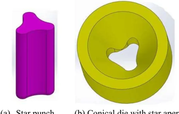
II. PROPOSED METHOD FOR ASYMMETRIC CUP DRAWING In the proposed process, asymmetric cups can be drawn by pushing a circular blank by the desired punch shape through a conical die, for which a conical die of a half cone angle α =18o
clover, rose, star or triangular cross-sections.
(a) Star punch (b) Conical die with star aperture Fig. 1. Pictorial illustrations of the drawing tools used for star cup drawing process
Fig. 2. Sequence of star cup drawing by the present process through a conical die without blank holder (die sectioned to clarify)
Fig.3. Star cup drawing by the conventional deep-drawing process with blank holder (blank holder and die sectioned to clarify)
III. FINITE ELEMENT SIMULATION MODELS A series of numerical experiments are performed with the commercial FE software DYNAFORM-PC, to evaluate the proposed process. Commercial purity Aluminum (Al, 99.5w) and Brass (Cu-Zn, 67/33) are used and an elasto-plastic material model with orthotropic Hill anisotropic hardening law is employed in the simulations. For the experimental verification, the same materials were used for the deep drawing of star cups. The material parameters of the sheets that were used are listed in Table 1. Thin shell elements with five integration points, using Gauss integration rule were used to model the blank. The deformable body mesh had an average element size between
2 and 3mm. Automatic adaptive mesh refinement was applied in every simulation during the assessment study in order to overcome the numerical divergence caused by the highly distorted regions. Die and punch were modeled as rigid bodies. The analysis of asymmetric cup drawing is based on the various cross-section geometries of the deep drawn parts. Four asymmetric cups with different cross-sections, namely: clover, star, triangle and rose were used as shown in Fig. 4. The anisotropic behavior of blank materials is represented by the average normal anisotropy r. A clearance ratio c/t0 =1.25 is kept constant between the die and the punch. The effectiveness of the proposed technique for asymmetric cup drawing was validated by carrying FE simulation for the conventional deep drawing. Also, a constant gap clearance ratio c/t0 =1.5 between die/punch and die/blank holder interface surfaces was adopted in FE simulation.
The deep drawing ratio DR of asymmetric cups for each cross section is defined by:
m
o A
D DR0.5
(1) From the principle of constancy of volume, cup depth,h is calculated as;
h
AoAm
Cm (2)where, Do and, Ao are the diameter and area of the initial circular blank respectively, Amis the mean cross-section area of punch and die cavity. Whereas Cm is the mean cross-section periphery of punch and die cavity.
To compare the possibility of producing the four shapes, die half cone angle (α) = 180, die fillet radius = 5 mm, punch profile radius = 4mm, die throat length = 2 mm, relative die clearance (c/to) = 1.25; and lubrication conditions have to be kept constant for the all shapes during the simulation processes. However, the blank diameter is changing until the drawing limit is obtained.
Fig.4. Four different cross section geometries of deep drawn cups analyzed (Dimensions in mm)
A. Failure Criteria
The LDR and the success or failure of the drawn part depends on whether tearing or wrinkling occurs first. To manage tearing at the punch corner, the simulation was carried out with a limitation on the maximum thinning of 25%, which is used as the critical fracture criteria and taken Blank holder
(a) Die with star aperture (b) Before forming (c) During Forming
Blank Punch
Die
Star aperture Throat
from Kobayashi [14]. However, due to the absence of blank holder and holding force at flange during the early stages of drawing, LDR is limited by occurrence of wrinkling which is controlled by the critical buckling stress of elements at the rim of the circular blank. The law of constant friction is assumed at the drawing tools-work piece interface, whereas the coefficient of friction remains constant throughout the forming process. The average values of the friction coefficients between the contacting surfaces of square punch/blank, and die/blank are taken to be 0.25 (Walker [15]) and 0.05 (Serway [16]), respectively.
The blank diameter (BD) is changed while other parameters are kept constant and simulation is repeated untill the LDR criterion is achieved. The drawing velocities, strains at the die contour orifice and the cup thickness distributions at different longitudinal cross sections are also studied. Because cups of star cross sections have a clear non-homogeneous flow forming; the finite element simulation focuses on the drawability limits and cup height versus blank thickness for star-shaped cups.
Table 1
Material properties, friction conditions and blank thickness
Blank Material Brass (CuZn37) Aluminum
(AL99.5w)
Hardening law, , MPa 0.42
575
0.12
7 . 166
Poisson's ratio, υ 0.34 0.30
Young's modulus E, GPa 97 66
Normal anisotropy, r 0.8 0.6
Absolute, R 0.06 0.325
Hardness, HV 68 37.5
Surface roughness, Ra, m (rolling direction)
0.21 0.26
Surface roughness, Ra, m(transverse direction)
0.34 0.33
d at blank/die interfaces 0.033 0.044 pat blank/punch
interfaces
0.174 0.215
Blank thickness to, mm 1.05, 1.55, 2.02, 2.49, 3.01
0.98, 1.46 1.91, 2.52, 3.02
B. Die Design Methodology
Studying the influence of geometrical parameter on drawing deformation is very important to find out the optimum setup dimensions that significantly increase the LDR. The effect of die angle, die fillet radius, die throat depth, punch nose radius, blank thickness, relative die clearance, are studied since they are the main geometric parameters in die design. For given material properties, friction conditions, initial blank thickness (to), blank diameter, BD, relative die clearance, die angle, die fillet radius and die throat the drawing ratio (DR) has been calculated. The blank diameter (BD) is changed while other parameters are kept constant and simulation is repeated till the LDR criterion is achieved. This procedure is performed for each geometrical parameter mentioned above and the
corresponding LDR has been calculated and then the optimum setup dimensions are determined.
IV. EXPERIMENTAL WORK
In order to validate the simulation results, experimental work was carried out on a computerized tensile test machine (Tinius Olsen model 290 Display). The maximum capacity of this machine is 1000 kN and it is equipped with a data acquisition system to automatically store, display and print the load displacement curves. Experiments were carried out at 8.33x10⁻⁴/s strain rate to guarantee a quasi-static state of deformation and as a result the strain-rate effect could be neglected (Hosford [17]). One die made of carbon steel was designed to have a conical zone with the half cone angle equal to 18o and a star cross-section with a throat depth of 2 mm. The conical die length was designed to be long enough for a sufficient range of blank diameters. The nominal dimensions of the star die cross-section are shown in Fig. 4 (c). The blank materials used in this work are commercial purity annealed Aluminum (Al, 99.5w) and annealed Brass (Cu-Zn, 67/33). Commercial grease was used as a lubricant between the blank-die-interface since it is a semisolid and has several important advantages over oil lubricant. Grease resists being squeezed out so it is useful under heavy load conditions and in inaccessible parts (such as contact surfaces between punch, sheet and die) where the supply of lubricant cannot easily be renewed. Also grease tends to form a layer that prevents the entry of dirt or grit between contact surfaces. The friction conditions, material properties and blank thicknesses of Brass and Aluminum sheet metals are listed in Table 1. Based on the dimensions of the star cross-section, given in Fig. 4 (c), the mean cross-section area Am
is 586.1843 mm2, while the periphery Cm is 148.78 mm. Experiments have been done with a relative die clearance ofc/to = 1.25 and different blank diameters for
each blank thickness in order to find the practical drawing limits. These experiments were identically simulated with FEA where the drawing depths and LDR were determined. The results of the simulations were compared with the results achieved from the experiment.
V. RESULTS AND DISCUSSIONS
process for deep drawing of asymmetric shapes was proven to be successful through assessments on four different die cross-sections.
The maximum drawing ratios along with the cup heights for the Brass and Aluminum sheet metals are summarized in Table 2. For instance, star cup heights are 50 mm for brass and 40 mm for aluminum. As mentioned earlier, the formation of the star cross section cups was rather challenging for the proposed process because it has a complex flow formation. Therefore, numerical and experimental investigations were focused mainly on the limiting equivalent drawing ratio, cup height, punch load and thickness distribution as well as the drawing velocities and strains at the die orifice of the star cross section.
Table 2
FE-Simulation successfully drawn cups and the corresponding limiting drawing ratios for to = 2.0 mm and
Brass (Cu-Zn 67/33).
Shape Conventional Deep
Drawing with blank holder
Drawing through conical die without
blank holder
Clover
92
2.07
112
2.53 BD, mm
LDR
Rose
105
2
120
2.28 BD, mm
LDR
Star
82
3
101
3.7 BD, mm
LDR
Triangle
95
2.14
115
2.6 BD, mm
LDR
A. Limiting Drawing Ratio and Cup Height
Figs. 5 and 6 show the effects of initial blank thickness on the LDR and the cup height (h), respectively. Experiments and simulations were conducted on Aluminum and Brass blanks with nominal thicknesses (1.0, and 2.0, 2.5 and 3.0 mm). The LDR and the cup height continued to show a significant increase until the blank thickness to reached 2 mm. Minimal subsequent LDR and height increases were then observed in relation to any additional blank thickness increase in LDR and height is attributed to the abruptly increase in the drawing loads. The increase of loads is due to the increase of buckling stiffness for larger sheet thickness. We also observed that a further increase of initial thickness does not lead to a significant increase in the LDR or cup height. This is because the buckling stiffness does not only depend on the blank thickness but also on its material properties as well. The predicted cup height and LDR agree well with the experimental values for both metals used in
this study. However, due to numerical errors there are slight differences between the predicted and the experimental values. These errors may be the result of the differences between actual material properties used in the experiment and those used in the simulation. Another source of error may stem from the differences between the nominal and the actual blank dimensions, as well as the use of constant coefficients of fiction in FE simulations. In case of brass, discrepancies between experimental and numerical results for cup height and LDR are significant, as shown in Figs. 5 and 6. These differences are mainly due to assuming normal anisotropy yield criteria for the sheet material. This assumption does not comply with the average planar anisotropy of the tested brass sheet since the planar anisotropy coefficient is about 16% away from being isotropic. Also, the average r-value of brass is higher than that of aluminum, which gives a high deformation resistance of blank in thickness direction and this in turn affects the predicted brass cup height and LDR. Presumably this might explain significant discrepancies between experimental and numerical results for LDR and cup height of brass cups.
Fig.5. Experimental and numerical equivalent limiting drawing ratio (LDR) versus sheet thickness for drawing cups of star cross section
Fig.6. Experimental and numerical cup heights versus sheet thickness for drawing cups of star cross section
B. Punch Load
punch load occurs when the deformed blank enters the star die throat. As expected the punch load increases as the blank thickness and size increase. The deformation resistance of the blanks increases with its volume and consequently the energy required for deformation will also increase. The maximum load of Brass is noticeably higher than that of Aluminum since Brass has a higher strength coefficient, a Young's modulus, and a strain hardening exponent. Cup wall wrinkling, fractures and tears occur at the bottom of the cups for the blank size just above the drawing limit, which is illustrated by the dotted curves. The word “failure” used in legends of Fig. 7 and Fig. 8 does only mean bottom fracture or bottom tear but it also means occurrence of wrinkling,. Generally cup failure occurs when a sheet metal blank is subjected to plastic deformation that exceeds the limit strain of the material or wrinkling due to oversized blank. Form experiments, when increasing blank size wrinkling “failure” was observed before any cup drawing even if the load obtained with two sheets is similar. This is because the compressive stress in circumferential directions reaches the critical buckling stress. Also the proposed process is not to use blank holder, which means the common mode of failure with increasing BD is the occurrence of wrinkling. What is shown in Fig. 7 and Fig. 8 is that the failure (wrinkling, fracture, or tear) is sensitive to the critical blank diameter (BD). For instance in Fig. 7 for blank thickness to = 2.49 mm failure occurs when BD diameter changes from 92 mm to 93 mm. And for blank thickness to = 1.92 mm failure occurs when BD changed from 89 mm to 90 mm. In the same manner Fig.8 shows that failure occurs for drawn brass cup when the critical BD equals 95 mm for to = 2.52 mm sheet thickness whereas BD is 91mm for 2.02 mm blank thickness.
Fig. 7. Experimental punch load-displacement curves for deep drawing of Aluminum cups of star cross section
C. Optimum Geometrical Parameters
Constraint optimization of six geometrical design parameters has been conducted by FE-analysis. Table 3 summarizes the predicted optimum values for these parameters. Maximum DR was archived at die angle 180 since the susceptibility for premature wrinkling is diminished. Die throat depth has a slightly opposite effect on the LDR, but the optimum die throat depth is 2mm in order
to minimize the frictional resistance force at the die throat surface area. Die fillet radius is necessary to remove the sharp edges formed due to the intersection between the internal conical die surface and its cross-section aperture. These edges cause a stress concentration, high contact pressure and friction force as well as abrupt change in blank thickness due to bending at sharp edges. LDR has been significantly increased at 9 mm die filet radius. Punch profile radius of 9 mm was the optimum value that minimized the effect of bending and at achieved high LDR. At 3 mm blank thickness, the maximum LDR was obtained since increase in buckling stiffness suppresses the occurrence of wall wrinkling. However, any further increase of initial thickness does not lead to significant increase in limiting drawing ratio. This is because the buckling stiffness does not only depend on the blank thickness but also on its material properties.
Fig.8. Experimental punch load-displacement curves for deep drawing of Brass cups of star cross section
Table 3
Geometrical parameters and its optimum values obtained by FE simulations
parameter Studied
values
Optimum value
die angle, degrees 10, 15, 18, 25, 35, 45, and 90o
18o
die throat depth, mm 2, 3, 7, 10 and 13 2
die fillet radius, mm 0, 3, 5, 10 and 15 9 punch profile radius, mm 1, 5, 9, 13, 17 and 19 9 blank thickness, to, mm 0.5, 1.0, 1.5, 2.0, 2.5
and 3, 4
3
relative die clearance, C/to 1.5, 1.2, 1.0, 0.9, 0.8 and 0.7
1.3
D. Possibility of the Present Process for Drawing Asymmetric Shapes
Several FE analyses and experiments on star cross-section cups were conducted to confirm the capability of the present proposed process. The star cross-section was chosen because it has a clear non-homogeneous and irregular deformation. Fig. 9 shows two examples of successfully drawn cups from brass and aluminum of equivalent limiting drawing ratios, LDR of 3.44 and 3.37 with heights 43mm
to =2.02 mm
t
o =2.51 mmt
o =2.49 mmto =1.92
and 39mm, respectively. The FE results and experiments have shown promising tools for producing deep cups of asymmetric cross-sections. The main objective of the experimental work presented is just to confirm the possibility of the current proposed process to produce star cross-section cups. In this sense, one or two experiments is sufficient, however 20 experiments have been done ( ten for brass and ten for aluminium sheets) and the standard deviation for LDR was 3% which confirms the reproducibility of the experiments. The current proposed process is promising and is still under development to produce elliptic and rectangular cups with extreme aspect ratios in a single stage and one punch stroke.
Brass cup (LDR= 3.44, average h=43 mm,
to=2.52mm)
Aluminum cup (LDR= 3.37, average h=39 mm, to=2.49mm
Fig. 9. Two examples of successfully drawn cups from brass and aluminum produced by conical dies
VI. CONCLUSIONS
A proposed process based on using conical dies was developed to increase the deep drawability of asymmetric cups with a clover, rose, star and triangular cross sections. Since the star cup shape has a clear non-homogeneous deformation, the experimental verification, drawability limits, drawing force, strain and thickness distributions evaluations were focused on this shape. Numerical simulations using elasto-plastic FEA confirmed the process ability to draw cups of these four shapes with significant drawing ratios that are higher than those of conventional deep drawing method. Experimentally, successful Brass and Aluminum cups of star cross-sections were obtained with LDR of 3.44 and 3.37, respectively. The present proposed technique has significantly increased the drawability of asymmetric cups by controlling the material flow and avoiding necking at the bottom corners of the cups. It is expected that this technique is able to produce cups of trapezoidal, elliptic, rhombic, cocoon-shaped, rectangular, and L-shape cross sections.
ACKNOWLEDGEMENT
This work was financially supported by the University of Malaya Research Grant UMRG: PR021B-13AET and high impact research (HIR) grant number HIR-MOHE-16001-00-D000027. The authors would like to thank Miss Noor & Mr. Fadzil for the proof reading of the paper.
REFERENCES
[1] Ku TW, Ha BK, Song, W. J., Kang, B. S. and Hwang, S. M., “Finite element analysis of multi-stage deep drawing process for high-precision rectangular case with extreme aspect ratio,” Journal of Materials Processing Technology, Vol. 130, pp.128–134, 2002. [2] Ku, TW, Kim, Y. and Kang, B. S., “Design and modification of tool
to manufacture rectangular cup of Ni-MH battery for hybrid cars,” Journal of Materials Processing Technology, Vol.187, pp.197–201, 2007.
[3] Seung-Ho, K., Kim, S. H. and Hoon, H., “Finite element inverse analysis for the design of intermediate dies in multi-stage deep-drawing processes with large aspect ratio,” Journal of Materials Processing Technology, Vol. 113, pp.779–785, 2001.
[4] Kim, S. H., Seung-Ho, K. and Hoon, H., “Design modification in a multi-stage rectangular cup drawing process with a large aspect ratio by an elasto-plastic finite element analysis,” Journal of Materials Processing Technology, Vol. 113, pp.766–773, 2001.
[5] Sheng, Z. Q., Jirathearanat, S. and Altan, T., “Adaptive FEM simulation for prediction of variable blank holder force in conical cup drawing,” International Journal of Machine Tools and Manufacture, Vol. 44, pp.487-494, 2004.
[6] Erkan, O. and Tekkaya, A. E., “Numerical simulation of various cross sectional workpieces using conventional deep drawing and hydroforming technologies,” International Journal of Machine Tools and Manufacture, Vol. 48, pp.532–542, 2008.
[7] Zhenyu, Hu.,“Realisation and application of size dependent FEM -simulation for deep drawing of rectangular work pieces,” CIRP Journal of Manufacturing Science and Technology, Vol. 4, pp. 4:90– 95, 2011.
[8] Anwar, K., “An experimental study of hydrofroming deep drawing,” Journal of Materials Processing Technology, Vol.134, pp.70-80, 2003.
[9] Lihui, L., Joachim, D., Karl, B. N. and Xibin, Z., “Investigation into the forming of a complex cup locally constrained by a round die based on an innovative hydromechanical deep drawing method,” Journal of Materials Processing Technology, Vol. 167, pp.191–200, 2005.
[10] Kang, D., Lang, L., Meng, X. and Xuan, J.,” Hydrodynamic deep drawing process,” Journal of Materials Processing Technology, Vol. 101, pp.21–24, 2000.
[11] Wijayathunga, V. N. and Webb, D. C.,”Experimental evaluation and finite element simulation of explosive forming of a square cup from a brass plate assisted by a lead plug,” Journal of Materials Processing Technology, Vol. 172, pp.139–145, 2006.
[12] Kalpakjian S. and Schmid, S. R., “Manufacturing Processes for Engineering Materials,” 5th edition PEARSON, Prentice Hill, 2013. [13] Hezam, L. M. A., Hassan, M. A., Hassab-Allah, I. M. and El-Sebasi,
M. G., “Development of a new process for producing deep square cups through conical dies,” International Journal of Machine Tools and Manufacture, Vol. 49, pp.773-780, 2009.
[14] Kobayashi, S., Oh S. I. and Altan T., “Metal Forming and Finite Element Method,” Oxford University Press, Oxford, 1989.
[15] Walker, J. S., “Physics,” 2nd edition. Pearson Education, New Jersey, p. 139, 2004.
[16] Serway, R. A., “Physics for Scientists and Engineers: With Modern Physics,” 3rd edition. Prentice-Hall International, Inc., Englewood Cliffs, NJ, p. 126, 1990.