*e-mail: [email protected]
1. Introduction
Drill pipes are produced, classiied and standardized by API (American Petroleum Institute) with different code numbers such as J55, K55, N80, C75, C95, H40, and P 1101,2. The pipes used for vertical drilling are manufactured as seamless in steel grade N80. These kinds of pipes are relatively cheap and widely used in oilields. The other one which is used in directional drilling is low alloyed medium carbon steel grade 42CrMo43,4. These kinds of pipes are made up of hardened and tempered high quality steel bars and have friction welded tool joints.
The drilling pipes are usually welded by using GMAW (gas metal arc welding) method. Because of welding defects such as, gas porosity, bubble, distortions due to thermal effects of welding, the GMAW method does not prefer by industry. The friction welding process is one of the most economical and highly productive methods of joining dissimilar metals and alloys, in the tool industry5,6. This process utilizes the frictional heat and pressure generated between a stationary and rotating work piece to form a metallurgical bond7,8. In
most cases, the friction welding process is automated and a highly qualiied personal is not required for operating welding machines.
The joined drill pipes are used to transmit drill torque and pull back force during the directional drilling project. They are under the bear twist, pull back, friction and vibration during the course of drilling. When rotating the drill string, the bending stress values change, modifying the tensile stress values, basically in a pulsation mode. Pulsating compressive stresses appear only in the shoulder front zones in the API tool joints, where the compressive stresses are evoked by the assembling make-up of threaded connections. Bending
stresses exerted by bending moment from curvature of the hole and helical buckling of drill pipes are signiicantly magniied by tool joint stand-off 9,10.
Therefore, the extensive literature survey was carried out about friction weldability of dissimilar drill pipes. The effect of stress relief annealing on the properties of friction welded dissimilar drill pipes was also investigated. There isn’t conclusive study about friction weldadability of similar or dissimilar drilling pipes and an effect of stress relief heat treatment applied for friction welded N80-42CrMo4 couple. For this reason, the dissimilar drill pipes (N80-42CrMo4) were welded by friction welding method. The mechanical properties of weldment were determined and the microstructural examinations were carried out on the welded sample. In addition, an effect of stress relief annealing on the properties of friction welded dissimilar drill pipes was also investigated.
2. Experimental
2.1. Materials
The materials used in this study were N80 grade steel and 42CrMo4 grade medium-carbon steel. The chemical compositions of steels are given in Table 1. The dimensions of pipes are Ø 88 diameter, 9 × 100 mm length and 9 mm wall thickness.
2.2. Welding parameters
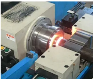
Dissimilar drill pipes were joined using a continuous drive Roto-friction welding machine (Figure 1). Welding parameters were set up according to pre-experimental studies. The applied friction and forge pressures were 50 bar (5 MPa) and 143 bar (14.3 MPa) while the chosen friction and upsetting times were 10 s and 9 s respectively. The rotating
Effect of Post Weld Heat Treatment Process on Microstructure and Mechanical Properties
of Friction Welded Dissimilar Drill Pipe
Hayriye Ertek Emrea*, Ramazan Kaçarb
aDepartment of Metal Education, Karabuk University, Karabuk, 78050, Turkey
bDepartment of Manufacturing Engineering, Karabuk University, Karabuk, Turkey
Received: July 16, 2014; Revised: April 4, 2015
In this study, N80-42CrMo4 dissimilar drill pipes were welded by a roto-friction welding machine. A set of welded samples were tested as-welded condition. Another set of welded samples were post weld heat treated (stress relief annealing) at the temperature of 600 °C, for 20 min. and then tested. The microstructures of the as-welded and stress relief annealed samples were examined by optical microscope and SEM. The properties of the all welded samples were determined by hardness measurement, tension and V notch-impact tests. The high hardness especially in the weld interface resulted in low toughness. As a conclusion, the stress relief annealing treatment caused a little decrease in yield strength and ultimate tensile strength, but increase in the elongation. The ductility of samples also increased after annealing treatment which is very important for static and dynamic loads.
Ertek Emre & Kaçar
504 Materials Research
speed of 1200 rpm was kept constant under the speciied friction upset distance during the joining.
2.3. Mechanical tests and metallurgical
evaluation
The structures and fracture surfaces of all the welded samples were evaluated by optic microscope and JEOL JSM 6335F type SEM (Scanning Electron Microscope). The samples were prepared according to classical metallographic method. They were etched with 2% nitric acid etchant.
The mechanical properties of welded samples were determined through hardness measurement, tensile and impact tests. Hardness proile was carried out in a line across the welded region under 200 g load and a dwell time of 15 s, using a Vickers microhardness testing machine.
Tensile test samples (Figure 2) were prepared according to ISO 4136: 2012 standard11. The samples were tested in tension, using a 100 KN load capacity Schimadzu tensile testing machine, at room temperature and a crosshead speed of 5 mm.min–1. In order to minimize the statically error, a set of three samples was tested for each condition.
The toughness of welded samples in different temperature conditions (–50 °C, 25 °C and 100 °C) were determined by Charpy V-notch impact test. Test samples were prepared according to the ISO 9016: 2012 standard12. They were tested by using a 300kJ load capacity MOHR&FEDERAF AG PSW 13/15 Charpy impact testing machine. The location of notch was positioned at the centre of the weld. A set of three test samples having 10 ×5 × 55 mm dimensions was used for each condition.
2.4. Heat treatment process of friction welded
samples
Before determining the mechanical properties and the metallographic examination, the stress relief annealing treatment was applied to a group of welded samples for a period of 20 minutes at a temperature of 600 °C in a furnace.
3. Result and Discussion
3.1. Microstructure
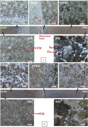
The microstructures of the samples, as-welded and annealed condition are shown in Figure 3a and b respectively. Three distinct zones across the weldment were identiied as fully plastically deformed zone (FPDZ), partially deformed zone (PDZ) and undeformed base metal (BM). FPDZ was observed on both sides of the weld interface region, which contains small recrystallized grains.
As it can be seen from Figure 3 that the microstructure of N80 BM consists of ferrite and pearlite and the structure of 42CrMo4 BM comprises of tempered martensite. The FPDZ of welded specimen consists of ine grains due to dynamic recrystallization and it has slightly coarser grain
than FPDZ. However, FPDZ zone has iner grains than BM (Figure 3). In other words, the effect of deformation in the PDZ is less than FPDZ, so the heat caused by friction is not enough for dynamic recrystallization to take place. Despite the coarse grain structure of PDZ, the overall bond region remains stronger than BM as proved by the plain tensile test results13.
Because of high carbon content and suficient friction heating followed by high cooling, the 42CrMo4 side of weldment adjacent to the weld interface are decorated with martensite phases. The martensite formation in the friction welded 42CrMo4 steel was also reported elsewhere14,15. Moreover, the prominent deformation bands caused by frictional force were observed in 42CrMo4 zone of the weldment.
The elemental mapping results for as-welded and annealed samples are shown in Figure 4a and b. The mapping results show that the chromium diffuses towards N80 steel from 42CrMo4 steel, while the manganese diffuses from N80 steel side towards 42CrMo4 grade steel. It has been reported that the elemental distribution across the interface, inter-diffusion of elements lead to formation of low ductility quasi-cleavage fracture in friction welding16,17,18. The extent of diffusion is
found slightly homogenous in annealed samples as compared with as-welded samples. The distribution of Cr, Mn, and Ni in weld interface almost exist in similar quantities.
Table 1. The chemical composition of the N80 and 42CrMo4 steel (%wt.).
Quality % C Si Mn P S Cr Mo Ni V Co W
N80 0.35 0.27 1.43 <0.001 0.01 0.09 0.007 0.05 0.06 0.01 0.01
42CrMo4 0.41 0.23 0.68 0.01 <0.002 0.96 0.15 0.027 <0.001 0.006 0.01
Figure 1. Friction welding machine.
3.2. Mechanical test result
The tensile test results are shown graphically in Figure 5. According to the Figure 5, there is a little decrease in yield and ultimate tensile strengths but slight increase in the elongation after annealing treatment. The maximum tensile and yield strength of as-welded and stress relief annealed samples were determined as 872 N/mm2, 851 N/mm2 and 570 N/mm2, 508 N/mm2, respectively. The elongation was also increased from 14% to %15. The failure of tensile test samples takes place on N80 BM side of the weldment. In other words, all friction welded samples are acceptable, because none of the welded samples were ruptured from the weld region. The failure occurred in the weakest part of the weldment where the strength of BM is normally low in dissimilar applications.
The stress relief annealing treatment was resulted in minimizing the residual stresses as well as the hardness of martensite phase in the FPDZ and PDZ of weldment. The annealing process generally leads to a decrease in residual stress, depends on the temperature and the annealing time14.
In order to understand the fracture behaviour of tensile test samples, the fractured surfaces were analysed by SEM. The fractured surfaces are shown in Figures 6a-d
The surface slip and necking region of test samples were evaluated. All the test samples exhibited a predominantly ductile fracture mode, since the failure was located in the N80 steel side of the weldment. Higher dimple density and
Figure 3. Microstructure of friction welded N80-42CrMo4 sample
N80-42CrMo4 sample a) As-welded, b) Stress relief annealed (TM: Tempered martensite, M: Martensite, P: Perlite, F: Ferrite).
Figure 4. The elemental mapping result of a) as-welded b) Stress
relief annealed N80-42CrMo4 couple.
Ertek Emre & Kaçar
506 Materials Research
reduction areas were observed in annealed samples. Test samples exhibited typical characteristic of cup–cone shaped fracture mode (Figure 6c). However, the annealed samples exhibited higher ductility than as-welded samples, Figures 6a and c. The relatively small size dimples which were surrounded by large coarse dimples and a small quantity of tearing ridge was observed in the structure of as-welded sample (Figure 6b). There was a notable difference observed in the appearance of dimples in the annealed samples. These samples were consisted of ine and uniform dimples, which indicate that the specimens failed in ductile manner under the tensile loading.
Hardness measurement was carried out on the cross section of the weldment, in the axial direction. The hardness proiles are shown inFigure 7.
As can be seen from Figure 7 that the hardness of the 42CrMo4 BM was measured to be 280 HV0.2. The maximum hardness of PDZ was 357 HV0.2 (max), whereas the measured maximum hardness of FPDZ was 488 HV0.2. The results indicated that the hardness of 42CrMo4 weldment notably increased from base metal towards weld interface, due possibly to the ine grains resulted from dynamic recrystallization and martensite formation. The results also showed that the FPDZ hardness was much higher than 350 HV0.2, which is not acceptable in the HAZ of C-Mn steel for fusion welding methods. Because of this, pre and post weld heat treatments are generally recommended for recovering the ductility as well as the toughness of the HAZ.
However, the hardness values of FPDZ and PDZ decreased to almost the same level as that of the base metals after stress relief annealing treatment (Figure 7). The hardness value for FPDZ of 42CrMo4 sample was measured as 295 HV0.2 (max), whereas for PDZ as 270 HV0.2 (max). The BM hardness of 42CrMo4 did not change and it was 278 HV0.2 (max). The decrease in the hardness could be either due to the tempering effects of stress relief annealing treatment on martensite phase or due to the minimized residual stress or due to the loss of work hardening effects in the weldment. The mechanical properties of friction welding processed low alloy steels are highly sensitive to the process parameters used during joining. Phase transformations resulting in metastable microstructures such as martensite and retained austenite can generally be
reverted to the more desirable ine ferrite carbide structure through stress relief annealing treatments19,20.
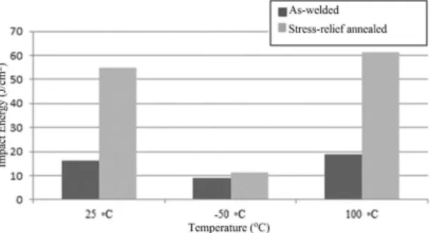
The toughness of the dissimilar welded samples was also investigated by using V-notch impact test at the temperatures of –50 °C, 25 °C, and 100 °C. The results are shown in Figure 8.
It was noted that the toughness of the weldment was found to be lower than those of both base metals due to thermo-mechanical effects of friction welding such as sensitivity to phase transformation and work hardening effects. The results also indicated that the toughness of as-welded samples increase by raising the test temperature. For instance, the toughness of weldment was determined 9 J/cm2, 16 J/cm2, and 19 J/cm2, for –50 °C, 25 °C, and 100 °C temperatures, respectively. Low toughness values can be either attributed to the formation of martensite phase at the weld interface or to the tendency of formation of second phase particles in the weld region of the as-welded samples. The carbon diffusion from 42CrMo4 to the N80 steel in weld interface may lead to the formation of hard and brittle carbide phases, which is also supported by Lippold & Odegard21. The low toughness can also be attributed to the inclusions at the weld interface22. The small amount of porosity can even be responsible for low toughness.
The toughness of the dissimilar weld metals was recovered by annealing heat treatment. The impact values obtained after heat treatment are 11 J/cm2, 55 J/cm2, and 63 J/cm2, for temperatures –50 °C, 25 °C, and 100 °C, respectively. An increase in toughness values can be either due to the tempering effects of martensite or due to the minimized residual stress, resulting from stress relief annealing. The annealing of metastable structures such as martensite and
Figure 6. The fractured surface of N80-42CrMo4 tensile test sample;
a and b) As-welded, c and d) Stress relief annealed.
Figure 7. The hardness proile of friction welded N80-42CrMo4
couple.
Figure 8. The charpy impact properties of as-welded and stress
retained austenite may be reverted to the more desirable ine ferrite carbides, which can also be responsible for increase in toughness.
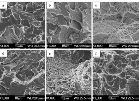
The fracture surfaces of the test samples were evaluated and fractographs are shown in Figure 9.
Figures 9a, b, d show that the quasi-cleavage is the dominant fracture mode in as-welded samples tested at the temperature of 20 oC as well as of –50 °C. This fracture mode can be due to the martensite phase formed in FPDZ and weld interface, or the elemental distribution across the weld interface. The interdiffusion of alloying elements has lead to formation of low ductility and predominantly quasi cleavage fracture (Figures 4a and b).
The ductile fracture mode was also observed in the samples which were tested at 100 °C temperature (Figures 9c and f). On the other hand, quasi-cleavage and ductile fracture mode are observed in the annealed samples tested at room temperatures (Figure 9e). The annealing process at the temperature of 600 °C caused a remarkable decrease in the cleavage facets. Figure 9 e and f show that the individual bright facets on the impact fracture surface in N80-42CrMo4 weldment are noticeably smaller than those in the Figure 9a and d. This result is attributed to the high concentration of ferrite/bainite and ferrite/tempered martensite interphase boundaries which can be the preferential sites for crack nucleation and propagation23,24.
Figure 9 e and f also show a large amount of dimples on the impact fracture surface of annealed N80-42CrMo4 couple, indicating a ductile fracture mechanism as well as a higher impact energy value. The reason is that the microstructure of N80-42CrMo4 weld interface comprises tempered martensite. The ferrite matrix includes signiicant amount of dislocation in addition to a large number of ine carbide particles in tempered martensite, which form dimples because of the manner of growth of grains in addition to micro void coalescence. This dislocation leads to the formation of a large
number of smaller dimples on the impact fracture surface N80-42CrMo4 weldment23,24.
4. Conclusions
In the present study, the friction weldability of dissimilar drill pipes is investigated. The effect of stress relief annealing process in microstructure evaluation and on mechanical properties is also determined. The obtained results are given below:
• The microstructure of the N80 base metal consists of ferrite and pearlite while the structure of 42CrMo4 base metal comprise of tempered martensite phase. The fully plastically deformed region of dissimilar welded sample consists of ine grains due to dynamic recrystallization. The 42CrMo4 side of weldment adjacent to the weld interface are decorated with martensite phases. • The elemental mapping result indicate that the chromium
diffuses towards N80 steel from the 42CrMo4 steel while the manganese diffuses towards 42CrMo4 steel side from N80 steel. The extent of diffusion is almost found homogenous in annealed sample.
• The stress relief treatment is responsible for small amount of decreasing in the yield and ultimate tensile strength. The annealing process produced an acceptable strength and ductility for friction welded N80-42CrMo4 couple. Test sample ruptured in a ductile manner under the action of tensile loading.
• The hardness is determined to be much higher than 350 HV in the joint interface and PDZ of 42CrMo4 side of weldment. The annealing at 600 °C for 20 minutes drastically decreased the hardness below the critical level of 350HV.
• The toughness of the weldment found to be slightly low at all test temperatures due to the martensite formation in the weld interface or the tendency of carbide precipitation in the weld region. The stress
Figure 9. The fracture surface of N80-42CrMo4 Charpy V-notch test sample tested at the temperature of –50 °C, 20 oC, and
Ertek Emre & Kaçar
508 Materials Research
relief annealing applied for welded sample improves to the toughness.
• The quasi-cleavage is the dominant fracture mode in as-welded samples tested at the temperature of 20 °C as well as of –50 °C, The annealing process caused a remarkable decrease in the cleavage facets and recovery in toughness of friction welded sample.
Acknowledgements
The authors acknowledge Karabük University, Project and Science Research Commission for their support. The friction welding process of the N80-42CrMo4 drilling pipe was carried out in the BRG machine company. The authors would like to thank Metallurgical Engineer Mr. Fatih BAŞ of BRG Machine Company.
References
1. Lepper GB. Production casing performance in a thermal field.
Journal of Canadian Petroleum Technology. 1998; 37(9):5-11.
2. Lu Q, Hannahs D, Wu J and Langford S. Connection performance evaluation for casing-drilling application. In: Offshore Technology Conference; 2007; Houston, Texas. 2007. p. 118-805.
3. Aranoff SL, Pearson DR, Okun DT, Lane CR, Williamson IA and Pinkert DA. Drill pipe and drill collars from China.
Washington: U.S. International Trade Commission; 2010. p.
204-236.
4. Cigni U, Fabri F, Giovannoni A. Geothermal cementing, cementing table, advancement in cementation techniques in the Italian geothermal wells. Report National Electric Energy Agency. 1975; 1-4.
5. Sahin M. Joining with friction welding of high-speed steel and medium-carbon steel. Journal of Materials Processing Technology. 2005; 168(2):202-210. http://dx.doi.org/10.1016/j.
jmatprotec.2004.11.015.
6. Ambroziak A, Korzeniowski M and Kustroń P. Friction welding of dissimilar metal joints with intermediate layers. Journal of Achievements in Materials and Manufacturing Engineering.
2007; 21(2):37-40.
7. Wang KK and Wen L. Fly wheel friction welding research.
Welding Journal. 1974; 53:233-241.
8. Wallace FJ. Friction welding. 1978. p. 719-728. ASM Handbook.
9. Özüdoğru S. Casing design and cementing in geothermal wells. In: Casing Symposium; 1996; İzmir, Turkey. 1996. p. 132-134.
10. Bednarz S. Design and exploitation problems of drill string in directional drilling. Acta Montanistica Slovaca Ročník. 2004; 9:152-155.
11. International Organization for Standardization - ISO. ISO 4136:2012: Destructive tests on welds in metallic materials, Transverse tensile test. Geneva; 2012. Available from: <http://
www.iso.org/iso/catalogue_detail.htm?csnumber=62317>. 12. International Organization for Standardization - ISO. ISO
9016:2012: Destructive tests on welds in metallic materials - Impact tests - Test specimen location, notch orientation and examination. Geneva; 2012.
13. Satyanarayana VV, Madhusudhan Reddy G and Mohandas T. Dissimilar metal friction welding of austenitic–ferritic stainless
steels. Journal of Materials Processing Technology. 2005;
160(2):128-137. http://dx.doi.org/10.1016/j.jmatprotec.2004.05.017.
14. Behnken H and Hauk V. Micro-residual stresses caused by deformation, heat, or their combination during friction welding.
Materials Science and Engineering A. 2000; 289(1-2):60-69.
http://dx.doi.org/10.1016/S0921-5093(00)00923-0.
15. Mitelea I and Craciunescu CM. Parameter influence on friction welding of dissimilar surface-carburized/volume-hardened
alloyed steels. Materials & Design. 2010; 31(4):2181-2186.
http://dx.doi.org/10.1016/j.matdes.2009.10.051.
16. Arivazhagan N, Singh S, Prakash S and Reddy GM. Investigation on AISI 304 austenitic stainless steel to AISI 4140 low alloy steel dissimilar joints by gas tungsten arc, electron beam and friction welding. Materials & Design. 2011; 32(5):3036-3050.
http://dx.doi.org/10.1016/j.matdes.2011.01.037.
17. Cheng CJ. Transient temperature distribution during friction welding of two dissimilar materials in tabular form. Welding Journal. 1963; 42(5):233-240.
18. Wang KK. Friction welding. WRC Bull; 1975.
19. Tumuluru MD. A parametric study of inertia friction welding for low alloy steel pipes. Welding Journal. 1984; 63:289-294.
20. Sudha C, Terrance ALE, Albert SK and Vijayalakshmi M. Systematic study of formation of soft and hard zones in the dissimilar weldments of Cr–Mo steels. Journal of Nuclear Materials. 2002; 302(2-3):193-205. http://dx.doi.org/10.1016/
S0022-3115(02)00777-8.
21. Lippold JC and Odegard BC. Microstructural evolution during inertia friction welding of austenitic stainless steels. Welding Journal. 1984; 63:35-38.
22. Dunkerton SB. Toughness properties of friction welds in steels.
Welding Journal. 1986; 65(8):193-202.
23. Wang P, Lu SP, Xiao NM, Li DZ and Li YY. Effect of delta ferrite on impact properties of low carbon 13Cr-4Nimartensitic stainless
steel. Materials Science and Engineering A. 2010;
527(13-14):3210-3216. http://dx.doi.org/10.1016/j.msea.2010.01.085.
24. Xu T, Jin Z, Feng Y, Song S and Wang D. Study on the static and dynamic fracture mechanism of different casing-drilling
steel grades. Materials Characterization. 2012; 67:1-9. http://